Manipulating Magnetic Resonance Image Contrast
Objectives
At the completion of this chapter, the student should be able to do the following:
• Identify the radiofrequency (RF) pulse sequence used to produce T2-weighted images.
• Identify the RF pulse sequences required to produce proton density–weighted images.
• Identify the RF pulse sequences required to produce proton T2*-weighted images.
• Plot T2 relaxation and its relation to T2* relaxation.
• Identify the RF pulse sequences required to produce T1-weighted images.
• Explain how MRI contrast agents are used to change relaxation times.
Key Terms
Basic magnetic resonance image contrast is affected by the amplitude and timing of the RF pulses used to excite the spin system. More advanced methods may use gradient pulses (to modulate motion) and alter tissue properties with exogenous contrast agents. Previously we have discussed the main intrinsic, tissue MRI parameters that affect image contrast: water density or proton density, longitudinal relaxation time (T1), and transverse relaxation time (T2).
There are several other important intrinsic tissue parameters that will be considered in later chapters. These include chemical shift, which is the difference in the resonant frequency between proton nuclei in water and proton nuclei in fat molecules. Tissue motion, which includes both macroscopic motion (breathing, blood flow, peristaltic motion) and microscopic motion (perfusion and diffusion), is an additional important consideration. Also we will take into account differences in the magnetic susceptibility of various tissues.
Although the properties of the tissues are important, the contrast in MR images is controlled by a number of user-selectable parameters, which are predetermined by the technologist at the MRI operating console. Magnetic field strength is also important, but this is determined when the equipment is purchased and cannot be changed.
Image contrast in MRI is principally controlled by the timing of radiofrequency (RF) pulses using specific delays (TR, TE, TI, etc.) and modifying the amplitudes of these pulses to control the flip angles. A large number of other parameters also influence contrast in specific circumstances, including the amplitude and timing of the gradients, the excitation frequency of the RF pulses, the bandwidth of the RF pulses, and the bandwidth of the MRI receiver subsystem.
All of these parameters will be considered in following chapters. In this chapter, however, we will focus on the relaxation times that we previously discussed and how the timing and amplitudes of the RF pulses can be used to exploit them to maximize soft tissue image contrast.
Although the following section describes methods for modifying image contrast based on the relaxation times, we should note that it is also possible to measure the relaxation times directly and produce images of the relaxation times (called parametric maps). This approach is used primarily in research since it is time-consuming and computationally intensive. However, recently some studies using injected contrast agents have included relaxation time maps, and this topic will be considered in Chapter 27. In current clinical practice, relaxation times are not measured or calculated; they are referred to as relative weighting of an image.
How to Make T2-Weighted Images
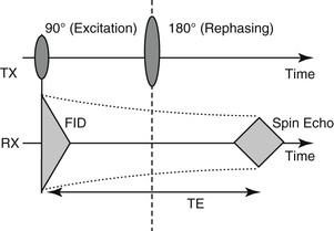
The radiofrequency (RF) pulse sequence shown in Figure 7-1 results in a magnetic resonance (MR) signal, the spin echo (SE). The FID does not relax according to the T2 of the sample because of B0 inhomogeneity; so how can we make the signal truly dependent on T2? Several methods have been developed, all of which use additional pulses after the initial 90° RF pulse. The spin echo pulse sequence is the most common of these (see Chapter 4).
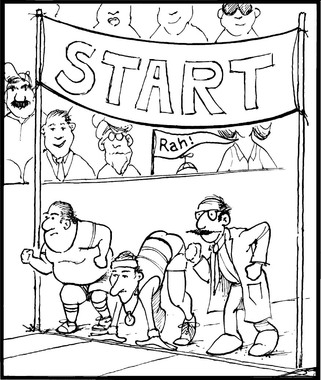
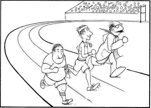
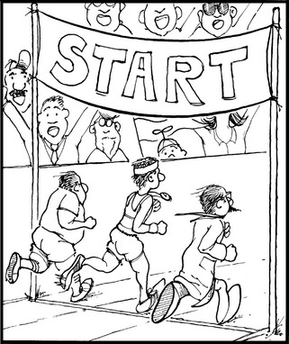
In Figure 7-2, the net magnetization in the three regions of the patient is represented by three runners on an oval track. At time zero, they all leave the starting line together. A perfect magnet system is represented by runners moving at exactly the same speed, so that at some later time the runners are still exactly together and in step (Figure 7-3).
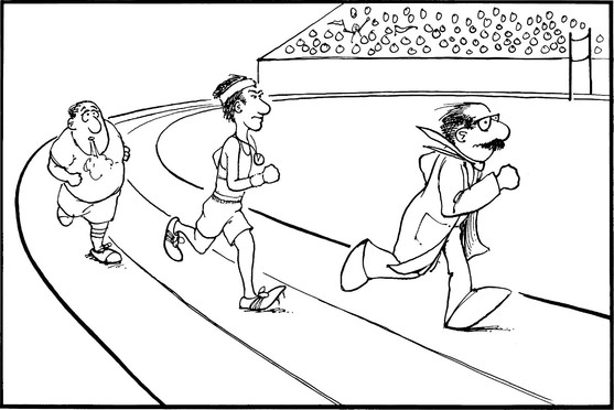
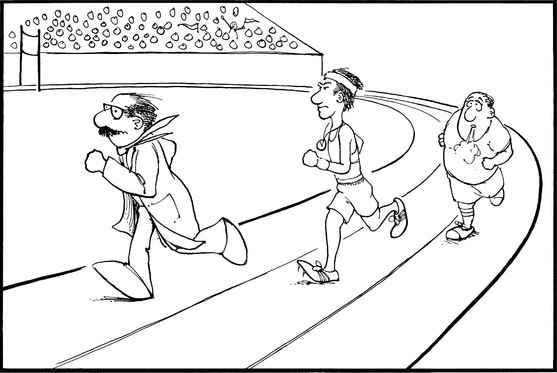
However, in a real magnet the net magnetizations in the three regions dephase because spins are precessing at slightly different rates (Figure 7-4). The runners start together but each runs at a slightly different speed, so that after some point in time, they are no longer together.
Is there some way to cause the runners to come back together even though they each run at a different speed? It is possible if a new rule is introduced to the race. For example, at the time in Figure 7-4, a whistle is blown, and all the runners immediately have to turn around, reversing their direction, and run back toward the starting line.
If the race is now run making use of this rule, the scene will change. The runners start out together but soon begin to separate, that is, dephase. Now at time A, the whistle is blown, and all the runners reverse and start running back toward the starting line. Suddenly the fastest runner, who was far ahead, is behind, and the slowest runner, who was behind, is in the lead. Even though they have changed directions, they have not changed speed. Therefore even though the faster runner is now behind, he will catch up with the others.
 A 180° RF pulse causes spins to rephase and form a spin echo.
Running toward the starting line is exactly the reverse of the start, when the runners ran from the starting line. This means that as the runners cross the starting line (Figure 7-5), they will again be precisely together; they are in phase again. They will cross the starting line at a time exactly twice that when the whistle was blown. For example, if the whistle was blown at 20 seconds, “rephasing” of the runners occurs at 40 seconds.
If the race continues, the runners again dephase (Figure 7-6). However, they can then be forced to rephase by blowing the whistle again, which will cause them to reverse direction again and come together at the starting line.
This process can be repeated any number of times. Each time the runners will rephase, and the information lost because of the difference in runners’ speeds is recovered. The difference in the runners’ speeds is analogous to the dephasing that occurs as a result of magnetic field inhomogeneities.
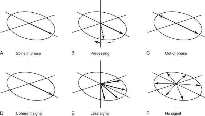
In a magnet, the runners (also known as spins) start out going both clockwise and counterclockwise (Figure 7-7) and the reversals of the runners are accomplished with 180° RF pulses. Each 180° pulse causes all the net magnetization vectors to flip 180°, in essence, reversing their direction. The spins then begin to rephase, and as they do, a signal is generated. The maximum signal occurs at the point where they are again in phase (Figure 7-8). If the 180° RF pulse were at time t, the maximum rephasing would occur at time 2t.
Related posts:
Stay updated, free articles. Join our Telegram channel

Full access? Get Clinical Tree


