Steady State Gradient Echo Imaging
Objectives
At the completion of this chapter, the student should be able to do the following:
Key Terms
In 1984, the desire for faster imaging led to the introduction of a group of pulse sequences. These pulse sequences lack the 180° radiofrequency (RF) refocusing pulse used in spin echo (SE) imaging. The elimination of the 180° RF pulse allows the use of a shorter repetition time (TR) than is possible with SE imaging. This results in a decrease in the available longitudinal magnetization (MZ), leading to a lower signal-to-noise ratio (SNR) and less contrast than if TR were shortened while the flip angle remained at 90°.
The solution to this problem was extracted from nuclear magnetic resonance (NMR) spectroscopy in which the flip angle is not fixed at 90°. Rather, it is optimized for the TR of the measurement and the spin-lattice relaxation time (T1) of the sample. The use of excitation flip angles less than 90°, i.e., the use of an α pulse, and the omission of the 180° RF refocusing pulse have allowed adequate SNRs within shorter sampling times.
 In gradient echoes (GREs), spins are refocused with a gradient magnetic field, rather than a 180° RF pulse.
The Gradient Echo
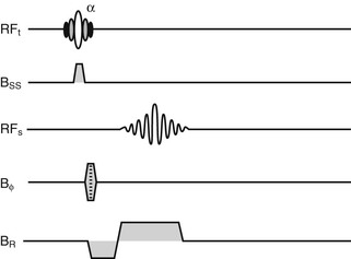
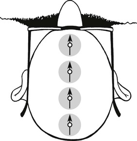
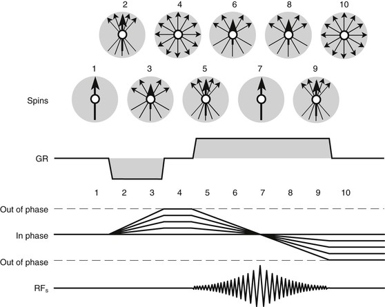
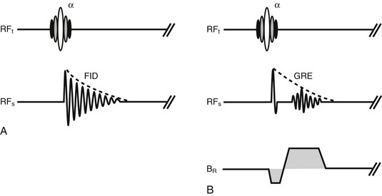
Figure 18-1 shows the basic pulse sequence for GRE imaging. Immediately after a low flip angle excitation, α pulse, in the presence of a slice-select gradient magnetic field (GSS), a free induction decay (FID) is generated. The negative lobe of BR is a rephasing lobe. Spins are in phase and precessing at the same frequency (Figure 18-2).
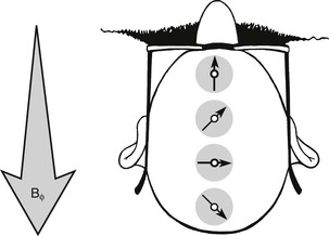
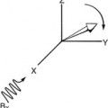
As in SE imaging, the phase-encoding gradient magnetic field (Gф) is energized momentarily to produce a difference in phase along the Y-axis. The spins in any column along the Y-axis precess at the same frequency, but now a difference in phase occurs (Figure 18-3). Still, each spin relaxes with equal T2* relaxation time.
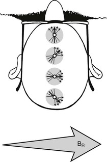
If a frequency-encoding read gradient magnetic field (GR) is energized simultaneously with or after the phase-encoding gradient magnetic field Gф, the spins dephase with T2* relaxation time (Figure 18-4).
The read gradient magnetic field, GR, causes a range of resonance frequencies during data acquisition. This range in frequencies also causes dephasing, which needs to be considered and compensated. Providing GR with opposite polarity and half the duration of that same gradient during the data acquisition causes an accelerated dephasing; this is followed by rephasing and the generation of a gradient-refocused echo, which is known as a gradient echo or GRE (Figure 18-5).
Another view of this method of echo formation is shown in Figure 18-6. The GRE is shown here as forming within the FID. This is the principal reason GRE can be so fast.
T2 Versus T2*
The GRE signal is generated from an FID when the dephasing gradient is applied early in the FID and immediately reversed. The GRE forms within the time of the FID, and the amplitude depends on T2*.
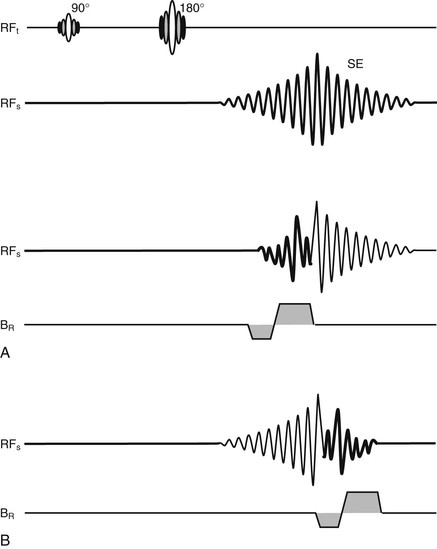
When an SE is used to generate a GRE, the refocusing GR can be switched during the first half of the SE (Figure 18-7, A) or after the center of the SE (Figure 18-7, B). In either case, the amplitude of the GRE depends on T2*. Radiologists rarely use this technique because it requires more time.
In addition to the gradient magnetic fields that are energized in conjunction with a selective excitation α pulse for the purpose of spatial encoding, patient- or system-related factors cause spin dephasing, which makes T2* still shorter. Inhomogeneity of the primary static magnetic field (B0) and the magnetic susceptibility differences among tissues are typical sources for such spin dephasing.
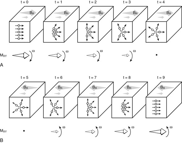
The influence of B0 inhomogeneity is further described in Figure 18-8. The voxel in Figure 18-8, A, contains five spins aligned and in phase to produce transverse magnetization, MXY, precessing with frequency ω. These spins dephase with time because of T2 relaxation.
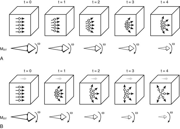
In Figure 18-8, B, the B0 does not have uniform intensity (magnetic field inhomogeneity) as indicated by the small arrow. The result is accelerated relaxation (dephasing), which is T2* relaxation.
Even faster relaxation will result if a gradient magnetic field is applied to the voxel. In Figure 18-9, A, the application of GR causes the spins that were dephasing with T2* relaxation time to dephase even more rapidly. If the polarity of GR is reversed, as in Figure 18-9, B, the accelerated dephasing is reversed and the spins rephase to form a GRE. The amplitude of this GRE is that of the FID at that time of relaxation.
Because they usually remain at the same location and are constant over time, these dephasing mechanisms are refocused with the 180° RF pulse used in SE imaging. The amplitude of the signal intensity in SE imaging depends on T2, not T2* (Figure 18-10, A).
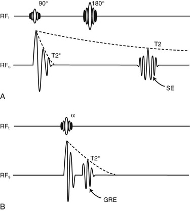
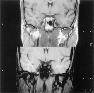
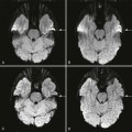
With GRE imaging, the additional dephasing mechanisms contribute to the image contrast and the apparent spin-spin relaxation time is dominated by T2*, rather than T2 (Figure 18-10, B). Figure 18-11 shows the dephasing effects of magnetic susceptibility gradients at the base of the skull.
Steady State
One of the first groups to develop GRE imaging called its technique fast low angle shot
Related posts:


Stay updated, free articles. Join our Telegram channel

Full access? Get Clinical Tree


