Shoulder, Including Clavicle and Scapula
John H. Harris Jr.
For the purpose of this discussion, the shoulder shall be considered to consist of the clavicle, including the sternoclavicular joint, the scapula, the scapulohumeral joint, and the proximal third of the humerus. This concept is anatomically and radiographically imprecise but has practical clinical relevance. The anatomy of the shoulder includes only the distal clavicle, the glenohumeral joint, and the proximal humerus, which governs positioning for the radiographic examination of the shoulder.
Clinically, injuries to the shoulder may include the entire clavicle (sternoclavicular separation, scapulothoracic dislocation). For this reason, it seems appropriate to include the entire clavicle in the discussion of the shoulder. One must remember that this inclusion is for clinical purposes only and that, as described in the text that follows, positioning for radiographic examination of the shoulder is completely different than positioning to examine either the clavicle or the scapula. The clavicle and scapula are discussed separately later in the chapter.
Although the shoulder is a large, seemingly relatively simple joint, its “motions are more extensive than those of any other joint in the body,” and therefore it must not be considered an uncomplicated structure radiographically.1 The anatomy of the shoulder and its relation to the trunk are the basis of serious radiographic diagnostic pitfalls peculiar to this joint. For example, partial or complete acromioclavicular separation, fracture of the coracoid process, and direct posterior dislocation of the shoulder present special radiographic diagnostic problems. If disruption of the acromioclavicular fibers is complete while the coracoclavicular ligament remains intact, separation of the acromio-clavicular space may not occur unless the acromio-clavicular joint is stressed. Consequently, when an acromioclavicular separation is suspected, special views of the shoulder must be obtained. The radiographic examination of the uninjured shoulder serves as a normal baseline study for comparison with the similar examination obtained of the injured side. A minimally displaced fracture of the coracoid process of the scapula may be established only on the axillary projection of the shoulder. Direct posterior dislocation of the shoulder is extremely difficult to diagnose on routine anteroposterior (AP) radiographs of the shoulder. Superimposition of the humeral head on the glenoid fossa or widening of the space between the humeral head and the glenoid fossa has been described as a sign of posterior dislocation of the shoulder. However, neither is sufficiently consistent to be reliable, and special views are necessary to establish this diagnosis. Apophyses are common about the shoulder. These normal structures, as well as the proximal humeral epiphysis, may create radiographic enigmas. Sternoclavicular separation and scapulothoracic dissociation are major injuries that are commonly radiographically subtle.
RADIOGRAPHIC EXAMINATION AND ANATOMY
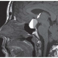
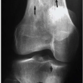
The routine radiographic examination of the shoulder is made with the patient in the AP position with the arm rotated both internally (Fig. 8.1A) and externally (Fig. 8.1B). When these projections are
made in the usual position, neither provides a true frontal view of the glenohumeral joint space. The latter requires rotation of the body into the posterior oblique position of the injured shoulder so that the plane of the scapula parallels that of the cassette with the central x-ray beam directed just medial to the articulating surface of the humeral head. The resulting radiograph (Fig. 8.1C) is the true AP projection of the glenohumeral joint and provides a true assessment of the glenohumeral joint space. These projections, which may be made with the patient either erect or supine, provide an adequate “survey” examination of the shoulder. However, as noted earlier, they frequently do not provide definitive data relative to some of the traumatic lesions involving the shoulder.
made in the usual position, neither provides a true frontal view of the glenohumeral joint space. The latter requires rotation of the body into the posterior oblique position of the injured shoulder so that the plane of the scapula parallels that of the cassette with the central x-ray beam directed just medial to the articulating surface of the humeral head. The resulting radiograph (Fig. 8.1C) is the true AP projection of the glenohumeral joint and provides a true assessment of the glenohumeral joint space. These projections, which may be made with the patient either erect or supine, provide an adequate “survey” examination of the shoulder. However, as noted earlier, they frequently do not provide definitive data relative to some of the traumatic lesions involving the shoulder.
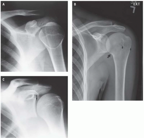 Figure 8.1. AP projections of the shoulder in internally (A) and externally (B) rotated projections; AP radiograph of the glenohumeral joint (C). In the internally rotated radiograph of the shoulder (A) obtained with the forearm flexed across the abdomen, the appearance of the humeral head has been likened to a light bulb or rifle barrel. The externally rotated view is taken with the humerus rotated outward so that the flexed forearm is perpendicular to the sagittal plane of the body. On this view, the inferior margin of the surgical neck (arrow), between the humeral shaft and head, is clearly visible. The cortex of the lesser (medial small arrow) and greater (lateral small arrow) tuberosities and the intervening bicipital groove are visible to varying degrees. The AP view of the glenohumeral joint (C) is the true frontal projection of the shoulder designed to show the glenohumeral joint space (arrow) and its contiguous surfaces. |
It is frequently necessary to obtain views of the shoulder made in planes other than the frontal projection. These may be either the axillary view (Fig. 8.2A) or “Y” projection (Fig. 8.2B).
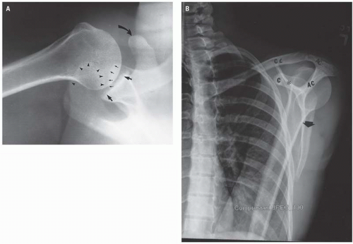 Figure 8.2. Axillary (A) and Y (B) radiograph of a normal adult shoulder. In the axillary projection (A), the relationship between the humeral head and glenoid fossa (large straight arrows) is obvious. The curved arrow indicates the anteriorly projecting coracoid process; small straight arrows indicate the distal clavicle; and arrowheads indicate the acromion. B: Y view of the left shoulder. In this slightly off-true axial projection, the supraspinous portion of the scapula (C) and the acromion process (AC) represent the arms of the Y. The infraspinous portion of the scapula (arrowheads) is the stem of the Y. |
The axillary view (Fig. 8.2A) should be considered in the radiographic examination of the shoulder in all cases of trauma to the shoulder. Although it is frequently overlooked, the axillary view provides more information about the shoulder than any other single projection. It is the only view in which minimally displaced fractures of the coracoid process of the scapula, cortical fractures of the anterior or posterior surfaces of the humeral head, posterior dislocation of the humerus, and direction of angulation of proximal humeral fracture fragments can be conclusively demonstrated. Positioning for the axillary view is very simple, and the demonstration of the anatomy of the shoulder is clear. The axillary view is best obtained with the patient supine.
A few words of caution are necessary relative to the use of the axillary projection in the evaluation of acute skeletal injury involving the shoulder. First, the axillary projection should be obtained only if the routine frontal projections do not permit a definitive radiographic diagnosis. Stated differently, the axillary view should not be part of the “routine” shoulder series of a patient who has sustained shoulder trauma. The axillary view is intended primarily for evaluation of glenohumeral joint injuries and may be contraindicated in patients with fractures of the proximal humerus. Second, contrary to the positioning described for the axillary projection in standard textbooks of radiologic positioning, it is not necessary to abduct the arm 90 degrees from the body to obtain a satisfactory axillary projection. Diagnostic axillary views (see, for example, Figs. 8.24, 8.25, 8.27, and 8.28) can be obtained with only sufficient abduction of the arm (10 to 15 degrees) to permit placing the x-ray tube between the hand and the hip with the central beam directed to the apex of the axilla. The cassette is placed above the shoulder in a plane perpendicular to the central x-ray beam. Finally, the radiologist should personally abduct the arm in order to ensure maximum control and minimum movement during positioning. The purpose for this caveat is, obviously, to prevent any unnecessary motion of the injured shoulder during this diagnostic examination.
The radiographic appearance of a normal child’s shoulder is seen in Figure 8.3.
 Figure 8.3. Frontal projection of the normal shoulder of a child. Arrows indicate the ununited humeral head epiphyses, and the asterisk marks the coracoid process of the scapula. |
Figure 8.4A illustrates the radiographic appearance of the normal adolescent shoulder. The apophysis of the coracoid process is clearly seen. The radiographic characteristics of the proximal humeral physis, namely, its dense sclerotic margins, variable width, and anatomic location, are illustrated at the anatomic neck of the humerus. This figure also illustrates the effect of position on the appearance of the physis and indicates how an arc of the physis may be projected in such a way as to resemble a fracture line. The ability of the proximal humeral physis to simulate a metaphyseal fracture is due to this physis being an essentially circular plane. Consequently, when the arm is displaced anteriorly or posteriorly from the coronal plane of the body during the radiographic exposure, the plane of the physis will be tangent to the x-ray beam and either the anterior or the posterior margin of the physis will project through the metaphysis, often resembling a metaphyseal fracture (Fig. 8.4B).
Routine radiographic examination of the noninjured contralateral part “for comparison purposes,” although advocated by Swischuk, may not be necessary in all instances.2 However, it is occasionally necessary to examine the contralateral shoulder radiographically because of the great variability of the proximal humeral physis and alterations in its radiographic appearance—usually secondary to positioning—that may simulate a fracture. For this reason, the shoulder is the part of the growing skeleton that is most frequently examined for comparison purposes.
The apophysis at the tip of the acromion (Fig. 8.5) and the apophyses at the base (Fig. 8.6) and tip (Fig. 8.4) of the coracoid process are normal structures that should not be misinterpreted as fractures. Again, the radiographic appearance of the apophyseal line surfaces and their characteristic locations should make this distinction relatively straightforward.
The scapula is difficult to visualize in AP projection because of its configuration, its orientation with respect to the posterolateral chest wall, its mobility, and superimposition of the clavicle, ribs, and humerus. The routine radiographic examinations of the shoulder described earlier do not provide an adequate radiologic study of the scapula. Therefore, when injury of the scapula is suspected, special scapular views must be obtained.3 These consist of AP (Fig. 8.7A) and lateral (Fig. 8.7B) (transscapular, tangential, axial, “Y”) projections. The AP radiograph of the scapula (Fig. 8.7A) is obtained with the patient either erect or supine and, optimally, rotated into approximately 45 degrees of ipsilateral posterior obliquity or sufficient obliquity so that the coronal plane of the scapula parallels that of the cassette. In the frontal projection, the medial border, varying amounts of the infraspinous portion, and the tip of the scapula are usually at least partially obscured by overlying ribs and lateral chest wall soft tissue. The coracoid process, which projects anteriorly, is seen essentially en face. This normal anatomy may render infraspinous and coracoid fractures invisible on frontal projections. In severely injured patients, the radiographic examination of the scapula may be limited to its appearance on the supine chest radiograph.
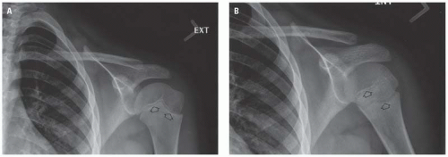 Figure 8.4. Straight AP radiograph of an adolescent left shoulder (A) showing the proximal humeral physis (open arrows) to be in the same plane. In the same patient, with the shoulder abducted (B), the physis is tangentially seen so that one margin could be misinterpreted as a metaphyseal fracture (open arrows). |
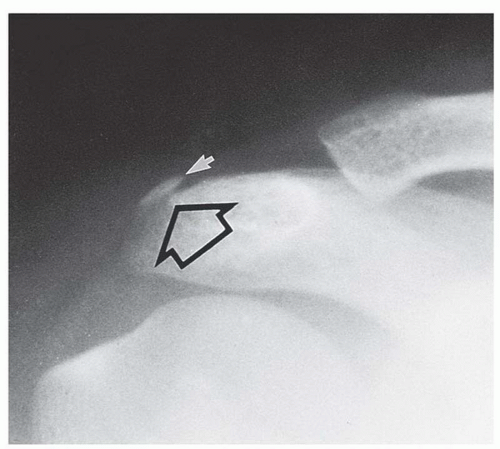 Figure 8.5. Physis at the tip (open arrow) of the acromial process. The location and radiographic appearance of this anatomic structure and the age of the patient should distinguish it from a fracture line. The lucent physis, in this instance, lies adjacent to the distal acromial apophysis (white arrow). |
When the patient’s condition will permit, the axial projection (Fig. 8.7B) of the scapula is obtained with the ipsilateral arm adducted anteriorly while the patient is rotated into ipsilateral anterior obliquity. In this position, the central x-ray beam is tangent to the coronal plane of the scapula, which, in turn, is perpendicular to the plane of the cassette. In this projection, the anteriorly projecting coracoid process represents the anterior arm of the Y; the scapular spine, its posterior arm; and the body, the vertical stem. The glenoid fossa, which forms the confluence of the Y, being en face to the central x-ray beam and covered by the humeral head, is usually not well seen on this projection.
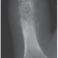
The routine radiographic examination of the clavicle (Fig. 8.8) consists of a straight AP and a tangential AP projection with the central beam angled rostrally and tangent to the anterior chest wall to project the clavicle off the ribs as much as possible.
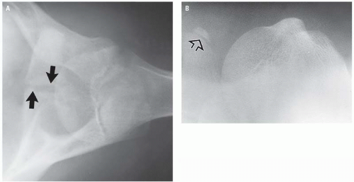 Figure 8.6. Normal physis at the base (arrows, A) and tip (open arrow, B) of the coracoid process. |
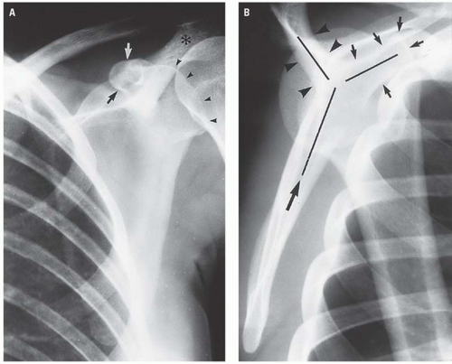 Figure 8.7. Frontal (A) and (Y) (B) projections of a normal adult scapula. In the frontal projection (A), arrowheads indicate the posterior margin of the glenoid fossa; the asterisk indicates the acromial process; and arrows indicate the anteriorly projecting coracoid process. On the Y projection of the scapula (B), the humeral head is superimposed on the glenoid fossa, which is at the junction of the coracoid process (small arrows), the spine (arrowheads), and the infraspinous portion of the scapula (large arrow). |
The inner third of the clavicle is best visualized on conventional radiography by projections designed to demonstrate the sternoclavicular joints. Individualized projections with varying degrees of tube angulation and patient rotation are frequently required to demonstrate this area radiographically. Computed tomography (CT) is the most definitive modality for diagnosis of subtle fractures and dislocations of the sternoclavicular joint. Because routine views of the clavicle may not demonstrate inner third fractures and because special projections may be necessary to establish the diagnosis, it is critical that the clinical impression be transmitted to the radiologist so that the appropriate views may be obtained.
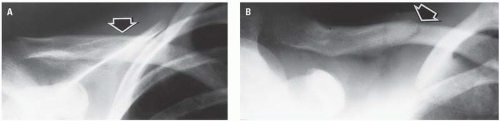 Figure 8.8. The complete fracture in the middle third of the right clavicle (arrow) can only be suspected in the straight AP projection (A). The presence of the fracture is clearly established, however, on the radiograph made with 15 degrees cephalad angulation of the x-ray tube (B). |
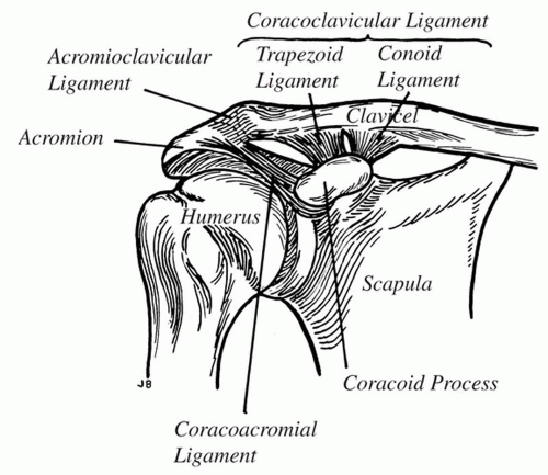 Figure 8.9. Schematic representation of the normal ligamentous attachments between the acromion and the coracoid process of the scapula and the clavicle. (Modified from Conwell HE, Reynolds FC. Key and Conwell’s Management of Fractures, Dislocations and Sprains. 7th ed. St Louis, MO: Mosby; 1961.) |
RADIOGRAPHIC MANIFESTATIONS OF TRAUMA
Acromioclavicular Separation
The diagnosis “acromioclavicular separation” refers to abnormal widening of the acromioclavicular (AC) joint due to disruption of the AC ligament, usually as the result of a direct trauma to the point of the shoulder. This terminology completely ignores the importance of the coracoclavicular (CC) ligament in the support of the upper extremity. Furthermore, the term AC separation is misleading because there is no reference to CC separation, which is the most important soft tissue injury caused by this type of trauma. The normal ligamentous anatomy between the clavicle and the scapula is indicated in Figure 8.9. Radiographically, the location of the AC and CC ligaments is seen in Figure 8.10.
Normally, the AC joint space should not exceed 4 mm in width in adults, and the distal inferior cortical margin of the clavicle and of the acromion should be on the same plane or arc (Figs. 8.1B, 8.5B, and 8.10). However, developmental variations in this relationship have been reported to be as high as 19%.4 Hypoplasia of the anterior tip of the acromion (Fig. 8.11) can result in apparent abnormal widening of the AC space and simulate a grade I AC separation.5
Both the AC and the CC ligaments play a role in the radiographic appearance of the effects of a blow or fall on the point of the shoulder. The AC joint is enclosed by a thin capsule that is reinforced superiorly and inferiorly by AC ligaments. The principal ligament between the clavicle and the scapula, however, is the CC ligament, which is thick, dense, and strong and is the principal ligament of attachment of the upper extremity to the torso through the clavicle. The extent of the CC separation has a direct bearing on the degree of AC separation.
Injuries of the AC (and CC) ligaments are traditionally classified as either sprain (type I), subluxation (type II), or dislocation (type III).6 More recently, types IV, V, and VI have been described.7, 8, 9
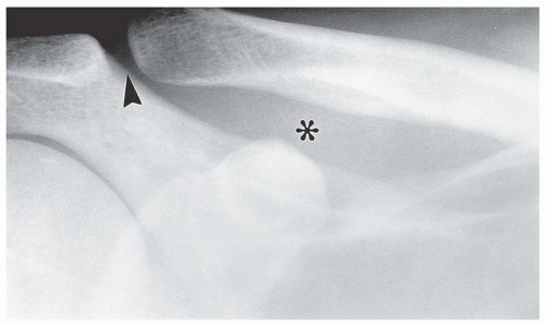 Figure 8.10. Normal adult shoulder. The location of the acromioclavicular and coracoclavicular ligaments is indicated by the arrowhead and asterisk, respectively. |
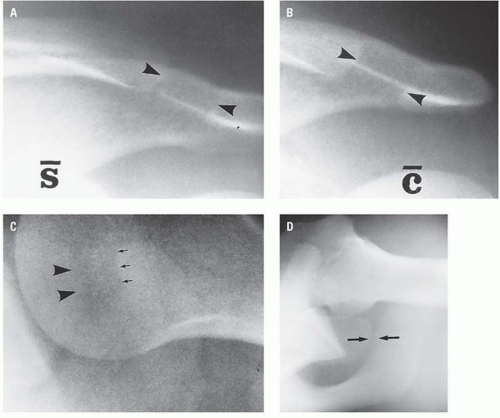 Figure 8.11. Anomalous acromial process simulating a grade I acromioclavicular separation. In the erect frontal radiographs of the shoulder without (A) and with (B) weights, the distance between the distal clavicle and acromion (arrowheads) is abnormally wide but does not change its contour with stress. On the axillary projection (C), the hypoplastic acromial process (arrows) is demonstrated to be the basis for the wide acromial (arrows)-clavicular (arrowheads) distance. The normal acromioclavicular relationship (arrows) is clearly depicted in the axillary view of a patient with an anterior shoulder dislocation (D). |
Type I AC separation (sprain) consists of stretching or tearing of a few fibers of the AC ligament. The AC joint remains stable, and the CC ligament is intact. This injury can be confirmed radiographically only by comparing stress views of the injured and uninjured shoulders. The radiographic sign of AC sprain is minor widening of the AC space (Fig. 8.12).
Partial or complete rupture of the AC ligament may exist with only partial disruption of the CC ligament (type II, subluxation) (Fig. 8.13), and the separation of the AC joint may not be evident on routine radiographs of the shoulder. Therefore, when “shoulder separation” is clinically suspected but not apparent on the routine shoulder radiographs, stress radiographs are required. These examinations are made with the patient in the erect AP position both with and without 10- to 15-lb weights being attached to each wrist. The weight is intended to stress the AC and/or CC ligaments of the affected shoulder, resulting in widening of the AC space as well as minimal widening of the CC space.
Inferior displacement of the scapula causes disruption of the continuous arc formed by the inferior cortices of the acromion and distal clavicle (Fig. 8.14). These alterations of normal anatomy indicate complete tearing of the AC ligament and either attenuation or partial disruption of the CC ligament.
The distinction between type I and type II AC separation is of greater theoretical than clinical importance because the radiologic distinction is frequently subjective and the treatment is usually nonsurgical.10
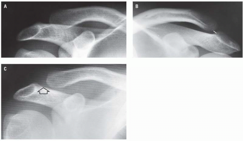 Figure 8.12. Type I acromioclavicular (AC) separation. This high school wrestler landed on the “point” of his right shoulder and experienced severe pain and point tenderness over the AC joint. The initial AP radiograph of his right shoulder (A) demonstrated only minor widening of the AC joint space (long white line) compared with a comparable projection of the left shoulder (short white line, B). Frontal views of the injured right shoulder (C) with weights confirm the widened AC space (open arrow). |
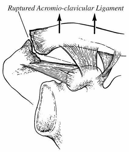 Figure 8.13. Schematic representation of type II acromioclavicular (AC) separation. Note that only the AC ligament is ruptured and that there is a slight separation of the AC space. (From Schultz RJ. The Language of Fractures. Baltimore, MD: Lippincott Williams & Wilkins; 1972. Used with permission.) |
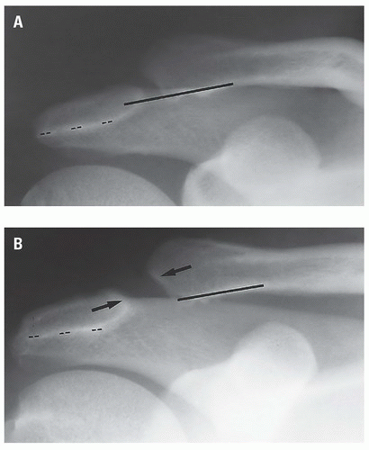 Figure 8.14. Type II acromioclavicular (AC) separation. In the non-weight-bearing frontal projection (A), the plane of the inferior cortex of the distal end of the clavicle (solid line) is superior to that of the inferior cortex of the acromial process (broken line). With weight (B), not only is the acromion more inferior to the clavicle, but the AC space (arrows) is abnormally widened, indicating disruption of the AC ligament. The coracoclavicular space is normal without and with weights, indicating that the coracoclavicular ligament is intact, although some of its fibers may be disrupted. |
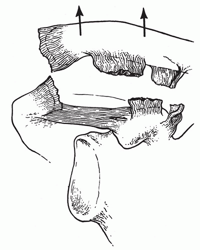 Figure 8.15. Type III acromioclavicular (AC) separation. This line drawing depicts complete disruption of the AC and the coracoclavicular ligaments. (From Schultz RJ. The Language of Fractures. Baltimore, MD: Williams & Wilkins; 1972. Used with permission.) |
When the force applied to the point of the shoulder is sufficient to disrupt both the AC and the CC ligaments, the scapula and its acromion are displaced inferiorly by the effect of gravity in the erect position, resulting in both AC and CC separation, for example, type III AC separation (Fig. 8.15). Radiographically, complete ligamentous disruption is represented by obvious widening of the AC and CC spaces in routine erect AP radiographs of the shoulder (Fig. 8.16). Type III AC separation is usually clinically obvious, and the diagnosis will be confirmed with only an erect AP radiograph of the shoulder (Fig. 8.17). When a type III AC separation is demonstrated on the erect radiograph, examinations of the shoulder with weights are not indicated. Conversely, a type III AC separation may be present and not radiographically visible on the supine frontal shoulder radiograph (Fig. 8.18). The common AC separation injuries are summarized in Table 8.1.
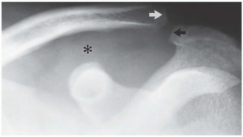 Figure 8.16. Erect AP radiograph of a type III acromioclavicular separation. The upper extremity, including the scapula, is displaced inferiorly by its own weight and the effect of gravity, resulting in inferior displacement of the acromion with respect to the distal clavicle (arrows) and widening of the coracoclavicular space (asterisk). |
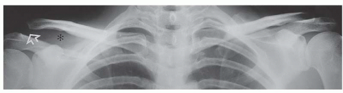 Figure 8.17. Type III right acromioclavicular (open arrow) and coracoclavicular separation (asterisk) is obvious on this frontal projection made with the patient erect and without stressing the shoulder. Compare the changes on the right with the appearance of the normal left shoulder. |
The type IV (posterior) AC separation occurs when the AC and CC ligaments are disrupted while the coracoacromial ligament remains intact (Fig. 8.19A). Radiographically, in AP (Fig. 8.19B) and axillary (Fig. 8.19C) projections, the distal end of the clavicle lies inferior and posterior to the acromion.
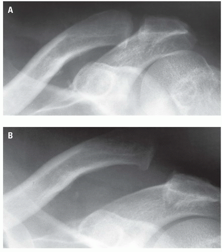 Figure 8.18. Type III acromioclavicular separation not visible in recumbency (A) but clearly evident in the erect frontal projection (B). |
TABLE 8.1 Acromioclavicular Dislocation: Classification and Prognosis | |||||||||||||||
|---|---|---|---|---|---|---|---|---|---|---|---|---|---|---|---|
| |||||||||||||||
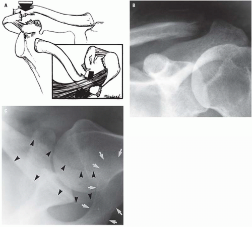 Figure 8.19. Type IV acromioclavicular (AC) separation. The schematic representation (A) shows disruption of the AC and coracoclavicular ligaments, the intact coracoacromial ligament and posterior displacement of the distal end of the clavicle. The inset (A) shows the posterior displacement of the distal end of the clavicle as seen in the axiliary projection. It is difficult to appreciate the posterior displacement of the distal end of the clavicle on the AP radiograph (B), although it is clear that the AC joint (arrow) is abnormal. The axillary projection (C) shows the posterior dislocation of the distal end of the clavicle (arrowheads) with respect to the acromial process (arrows). |
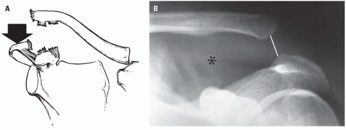 Figure 8.20. Type V acromioclavicular (AC) separation. The schematic (A) illustrates the mechanism of injury to be marked inferior displacement of the scapula by severe downward force delivered to the acromial process with only the coracoacromial ligament remaining intact. Subluxation (or dislocation) occurs at the sternoclavicular joint as well. On the AP radiograph (B), The AC (line) and coracoclavicular (asterisk) spaces are grossly wide and, because of the cephalad retraction of the proximal end of the clavicle by the sternocleidomastoid muscle, the clavicle assumes an almost horizontal attitude. |
Type V (inferior) AC separation refers to the severe inferior displacement of the scapula and occurs when, in addition to disruption of the AC and CC ligaments, some degree of sternoclavicular separation occurs as well (Fig. 8.20A). The latter allows the proximal end of the clavicle to be rostrally distracted by the unopposed action of the sternocleidomastoid muscle. The result, radiographically, is that the entire clavicle appears more severely rostrally located with respect to the scapula (Fig. 8.20B) than with type III AC separation. Conceptually, the type V AC separation can be considered a severe type III separation.
In the type VI AC separation, the distal end of the clavicle is displaced anteroinferiorly and comes to rest deep to the conjoined tendon of the biceps and coracobrachialis muscles (Fig. 8.21A). The ligamentous injuries and sternoclavicular disruption are the same as in the type V AC separation. On the AP radiograph (Fig. 8.21B), the distal end of the clavicle is located inferior to the coracoid process.
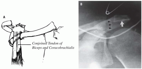 Figure 8.21. Type VI (anterior) acromioclavicular separation refers to the location of the distal end of the clavicle relative to the scapula. In the schematic (A), the distal end of the clavicle is depicted inferior to the coronoid process. The AP radiograph (B) shows the distal end of the clavicle (arrowheads) inferior to the acromion (arrow) but impinging on the top of the coracoid process (open arrow). (The glenohumeral joint is also posteriorly dislocated.) |
 Figure 8.22. Fracture of the distal end of the clavicle (arrow) with disruption of the coracoclavicular ligament (asterisk) and an incomplete tear of the acromioclavicular ligament. |
Fracture of the coracoid process associated with AC dislocation has been reported in approximately 20 cases.11 Recognition of this rare association has patient management implications.
Fracture of the distal end of the clavicle is commonly associated with tearing of the CC ligament with (Fig. 8.22) or without separation (Fig. 8.23) of the AC ligament. As with AC separations, the distal end of the clavicle is not retracted upward; rather, the effect of gravity and the weight of the upper extremity pull the distal fragment and scapula downward. In these kinds of fractures, the important injury is that to the CC ligament.
Glenohumeral Dislocation
The shoulder is the most frequent site of dislocation of any joint in the body, with dislocation of the shoulder constituting approximately 50% of all dislocations.12 The explanation for this incidence reflects the configuration of the humeral head and the glenoid fossa, the relative size of each, the weakness of the shoulder capsule, and the fact that this major joint is frequently subject to injury.
Dislocations of the shoulder, also referred to as glenohumeral instability and shoulder dislocation, are classified as “traumatic,” “atraumatic,” and “voluntary.”13, 14 Traumatic dislocations of the shoulder are the result of direct or indirect trauma, constitute 96% of glenohumeral dislocations,14 are usually unilateral, are the etiology of the Hill-Sachs fracture and the Bankart “lesion”,13 and usually ultimately require surgical management.13
Atraumatic dislocations occur as the result of a sudden forceful normal motion of the arm, as might occur during a seizure. Voluntary dislocations are those in which the patient is able to dislocate the glenohumeral joint at will. The latter two categories constitute only approximately 4% of glenohumeral instabilities. Voluntary instability is usually of congenital or developmental etiology, is usually bilateral, and usually responds to a rehabilitation program.13
Dislocations of the glenohumeral joint are also classified on the basis of the final resting place of the humeral head with respect to the glenoid fossa and are designated, therefore, as anterior, inferior, posterior, and superior.13, 15, 16, 17, 18, 19 Of these, the anterior dislocation, occurring most often as a subcoracoid (infracoracoid) dislocation (Figs. 8.24 and 8.25), is the most common. The inferior (subglenoid) (infraglenoid) dislocation is next in frequency. Posterior and superior dislocations are rare, as is luxatio erecta, a unique form of anterior dislocation. Glenohumeral dislocations have also been classified, perhaps more simply, into anterior (98%), which includes infracoracoid (most common), infraglenoid, infraclavicular, luxatio erecta, and the rare intrathoracic; posterior (2%), which may be subacromial (most common), subglenoid, and subspinous.19 Most posterior dislocations are subacromial and are fixed fracture-dislocations with the humeral head impacted on the posterior glenoid rim.
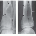
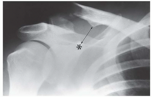 Figure 8.23. Fracture of the lateral third of the clavicle, resulting from severe force directed downward against the superolateral aspect of the shoulder. In this injury, the distal clavicular fragment retains its normal relationship to the acromial process indicating the acromioclavicular (AC) ligament is intact. The clinically significant injury associated with this type of clavicular fracture is disruption of the coracoclavicular ligament, indicated by the abnormally wide coracoclavicular distance (double-headed arrow). The asterisk indicates the coracoid process. Contrary to a common misconception, the distal end of the proximal fracture is not displaced upward by the sternocleidomastoid muscle, which inserts at the medial end of the clavicle. Rather, the entire upper extremity is displaced inferiorly by its own weight and the effect of gravity. |
In each classification system, the anterior dislocation, occurring most often as subcoracoid (infracoracoid) dislocation, is the most common. The inferior (subglenoid) dislocation is next in frequency.
Dislocations of the shoulder are usually clinically obvious. The indications for radiographic evaluation before reduction include establishing the type of dislocation, the relationship of the humeral head to the glenoid fossa, and the possible presence of associated fractures, particularly the impacted Hill-Sachs fracture. The axillary view is an essential component of the radiologic examination of patients suspected of having glenohumeral dislocation to confirm the direction of dislocation, assess impaction of the humeral head on the glenoid fossa in anterior dislocation and posterior fracture-dislocation, and after reduction to assess for Hill-Sachs fractures, which may be ambiguously depicted on the postreduction radiograph.
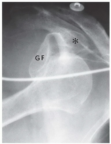 Figure 8.24. Anterior (infracoracoid) glenohumeral dislocation. The humeral head is displaced out of the glenoid fossa (GF) inferior to the coracoid process (asterisk) of the scapula. GF, glenoid fossa. |
Anterior dislocation is characterized by the humeral head coming to rest anterior to the glenoid fossa, typically inferior to the coracoid process (Fig. 8.24), hence the term infracoracoid dislocation. When it is difficult to distinguish infracoracoid from infraglenoid dislocation, the axillary view provides the definitive diagnosis (Fig. 8.25).
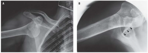 Figure 8.25. Infracoracoid dislocation in the axillary projection. (A) is the AP projection. Whether the glenohumeral dislocation is infracoracoid or infraglenoid is ascertained by the axillary projection (B), which indicates the infracoracoid position of the humeral head with respect to the glenoid fossa (arrowheads). |
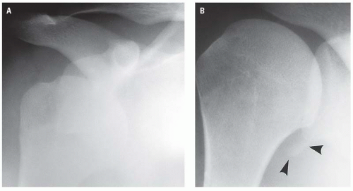 Figure 8.26. Anterior (infracoracoid) dislocation (A) with thin osteochondral fracture fragment (Bankart lesion) (arrowheads) of the anteroinferior glenoid labrum visible only in the postreduction radiograph (B). |
Glenohumeral dislocations—particularly the infracoracoid type—are commonly associated with injury to either the anterior or anteroinferior rim of the glenoid labrum (Bankart lesion) or the Hill-Sachs fracture. Each of these features may occur with the initial dislocation. Therefore, the presence of either fracture does not necessarily imply a previous or recurrent dislocation.20
The Bankart lesion, pathologically, may consist of disruption of the fibrocartilaginous labrum, detachment of a cartilaginous fragment, or an osteocartilaginous fracture fragment.21, 22,


Related posts:
Stay updated, free articles. Join our Telegram channel
Full access? Get Clinical Tree
