Shoulder/Arm
Thomas H. Berquist
Protocols
Key Facts
• Routine radiography
| ||||||||
• Arthrography
| ||||||||
|
Suggested Reading
Berquist TH. MRI of the musculoskeletal system, 5th ed. Philadelphia: Lippincott Williams & Wilkins; 2006:557–656.
TABLE 7-1 MAGNETIC RESONANCE IMAGING PARAMETERS FOR THE SHOULDER, ARM, AND BRACHIAL PLEXUS | ||||||||||||||||||||||||||||||||||||||||||||||||||||||||||||||||||||||||||||||||||||||||||||||||||||||||||||||||||||||||||||||||||||||||||||||||||||||||||||||||||||||||||||||
|---|---|---|---|---|---|---|---|---|---|---|---|---|---|---|---|---|---|---|---|---|---|---|---|---|---|---|---|---|---|---|---|---|---|---|---|---|---|---|---|---|---|---|---|---|---|---|---|---|---|---|---|---|---|---|---|---|---|---|---|---|---|---|---|---|---|---|---|---|---|---|---|---|---|---|---|---|---|---|---|---|---|---|---|---|---|---|---|---|---|---|---|---|---|---|---|---|---|---|---|---|---|---|---|---|---|---|---|---|---|---|---|---|---|---|---|---|---|---|---|---|---|---|---|---|---|---|---|---|---|---|---|---|---|---|---|---|---|---|---|---|---|---|---|---|---|---|---|---|---|---|---|---|---|---|---|---|---|---|---|---|---|---|---|---|---|---|---|---|---|---|---|---|---|---|
| ||||||||||||||||||||||||||||||||||||||||||||||||||||||||||||||||||||||||||||||||||||||||||||||||||||||||||||||||||||||||||||||||||||||||||||||||||||||||||||||||||||||||||||||
Fractures/Dislocations: Proximal Humeral Fractures
Key Facts
Fractures of the proximal humerus usually occur in the elderly.
Proximal humeral fractures account for 5% of all skeletal fractures.
Fractures in the elderly usually are caused by a fall.
Fractures tend to follow the physeal lines dividing the humerus into four parts: humeral head, greater tuberosity, lesser tuberosity, and shaft.
Fragments are considered displaced if separated by 1 cm or angulated 45 degrees or greater (Table 7-2).
The majority of fractures (85%) are undisplaced.
Undisplaced fractures are treated conservatively. Displaced, especially comminuted or four-part fractures, require surgery or hemiarthroplasty.
Complications:
Adhesive capsulitis
Neurovascular injury
Malunion, nonunion
Avascular necrosis
TABLE 7-2 NEER CLASSIFICATION | ||||||||||
|---|---|---|---|---|---|---|---|---|---|---|
|
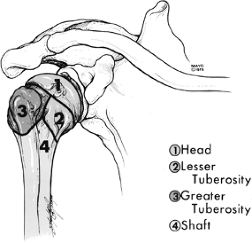 FIGURE 7-1 The four parts of proximal humeral fractures. |
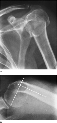 FIGURE 7-2 AP (A) and axillary (B) views of a comminuted impacted proximal humeral fracture. The fracture is angulated (lines) greater than 45 degrees. |
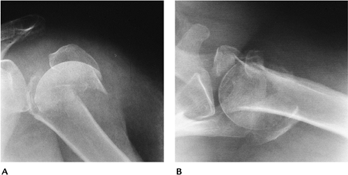 FIGURE 7-3 Four-part fracture with marked displacement of the fragments. The patient was treated with a shoulder prosthesis. AP (A) and axillary (B) views. |
Suggested Reading
Berquist TH, De Orio JK. The shoulder. In: Berquist TH, ed. Imaging atlas of orthopedic appliances and prostheses. New York, Raven Press; 1995:661–727.
Neer CS II. Displaced proximal humeral fractures. Part I: Classification and evaluation. J Bone Joint Surg 1970;52A:1077–1089.
Fractures/Dislocations: Glenohumeral Dislocations
Key Facts
Dislocations of the glenohumeral joint are the most common dislocation (50% of all dislocations).
Dislocations may be anterior (96%), posterior (2%–4%), or less frequently superior or inferior.
Anterior dislocations usually are the result of falls with the arm abducted and externally rotated.
The humeral head frequently is impacted against the labrum, resulting in a posterolateral impaction fracture (67%–76%) or Hill-Sachs lesion.
The anterior inferior labrum or glenoid also may be injured in 50% (Bankart lesion).
Most anterior dislocations are obvious on routine radiographs.
Posterior dislocations occur with seizures, shock therapy, or falls with the arm abducted and internally rotated. The patient’s arm is internally rotated, and external rotation is blocked.
Radiographic features may be subtle.
Humeral head fixed in internal rotation (100%)
Joint may appear widened
Overlap of humeral head and glenoid absent or distorted
“Trough line” in humeral head caused by anteromedial impaction fracture
Lesser tuberosity fracture (25%)
Scapular “Y” view makes diagnosis most obvious.
Treatment of dislocations is closed reduction unless there are significant associated fractures.
Complications of dislocations:
Associated fractures: lesser tuberosity, coracoid, greater tuberosity, subscapularis avulsion
Recurrent dislocation
Degenerative arthritis
Neurovascular injury
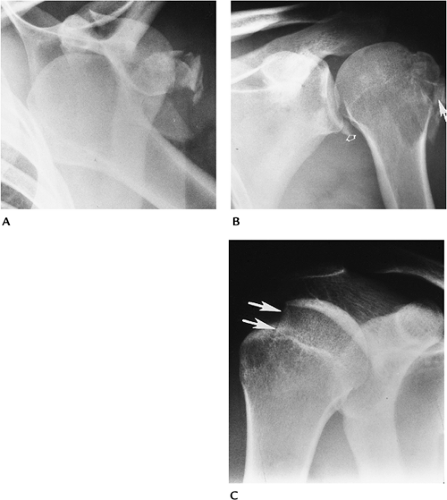 FIGURE 7-4 Anterior dislocations. (A) AP radiograph shows an anterior dislocation with fracture fragments laterally. (B) AP postreduction radiograph shows the tuberosity fracture (arrow) and Bankart lesion (open arrow) adjacent to the inferior glenoid. (C) AP radiograph demonstrates an impaction fracture (arrows) or Hill-Sachs lesion in a patient with a prior dislocation. |
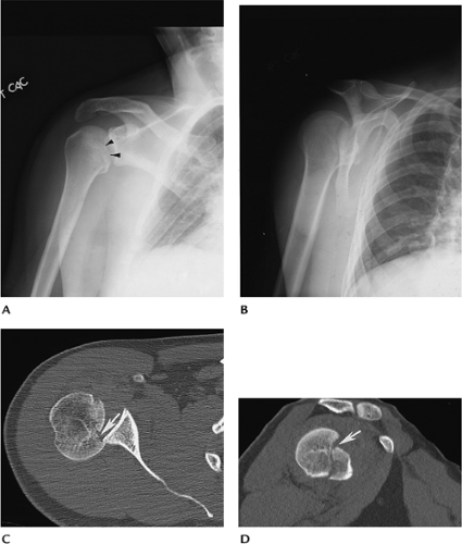 FIGURE 7-5 Posterior dislocations. (A) AP radiograph showing overlap of the glenoid and humeral head with an anteromedial impaction fracture (arrowheads). The humerus is fixed in internal rotation. (B) Scapular “Y” view clearly showing the posterior dislocation of the humeral head. Axial (C) and sagittal (D) CT images demonstrate the position of the head and the humeral head fracture (arrow). |
Suggested Reading
Robinson M, Aderinto J. Recurrent posterior shoulder instability. J Bone Joint Surg 2005;87A:883–892.
Turkel SJ, Pinto MW, Marshall JL, et al. Stabilizing mechanisms preventing anterior dislocation of the glenohumeral joint. J Bone Joint Surg 1981;63A:1208–1217.
Fractures/Dislocations: Acromioclavicular Dislocation
Key Facts
Dislocations of the acromioclavicular (AC) joint (12%) are less common than glenohumeral (85%) shoulder dislocations.
The injury usually is the result of a fall striking the point (AC joint region) of the shoulder.
Injuries may be partial or complete (Table 7-3).
Routine clavicle radiographs may be normal with incomplete ligament injury. Weight-bearing views are useful to classify injuries (Types I and II).
Closed reduction usually is used for Type I and II injuries. Internal fixation frequently is required for Type III to VI lesions.
TABLE 7-3 ACROMIOCLAVICULAR DISLOCATIONS | ||||||||||||
|---|---|---|---|---|---|---|---|---|---|---|---|---|
|
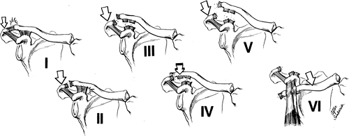 FIGURE 7-6 Acromioclavicular joint injuries. Type I: AC sprain, few fibers torn. Type II: disruption of the acromioclavicular ligaments with coracoclavicular ligaments intact. Type III: disruption of the AC and coracoclavicular ligaments. Type IV: disruption of both ligament complexes with posterior clavicular displacement. Type V: disruption of both ligament complexes with marked superior clavicular displacement. Type VI: disruption of the ligament complexes with anterior entrapment beneath the coracoid. |
Fractures/Dislocations: Acromioclavicular Dislocation
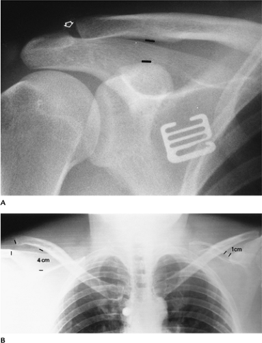 FIGURE 7-7 AC separation. (A) Normal coracoclavicular distance (lines) and slight AC joint widening (open arrow). (B) Weight-bearing stress view of both shoulders showing a coracoclavicular distance of 4 cm and a complete (Type III) separation (right). Note the normal relationship (left). |
Suggested Reading
Allman FL. Fractures and ligamentous injuries of the clavicle and its articulations. J Bone Joint Surg 1967;49A:774–784.
Fractures/Dislocations: Sternoclavicular Dislocations
Key Facts
Dislocations of the sternoclavicular joint are uncommon (3% of shoulder dislocations).
Injury usually occurs with indirect shoulder trauma. Anterior dislocation is the result of posterolateral forces transmitted medially. Posterior dislocation is the result of direct anterior trauma. Almost all (>90%) dislocations are anterior.
Radiographic evaluation is difficult with routine views because of bone overlap. CT is the technique of choice to evaluate the sternoclavicular joint.
Treatment usually is conservative.
Complications are most common with posterior dislocations: tracheal rupture, arch vessel laceration, neural injury.
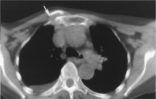 FIGURE 7-8 Axial CT image of an anterior sternoclavicular fracture dislocation (arrow). |
Suggested Reading
Nettles JL, Linsheid R. Sternoclavicular dislocations. J Trauma 1968;8:158–164.
Fractures/Dislocations: Clavicle Fractures
Key Facts
Clavicle fractures are especially common in children.
Injury occurs after a fall on the outstretched hand.
Fractures most commonly involve the middle third (80%). The distal clavicle is involved in 15% and medial clavicle in 5%.
Routine AP radiographs usually are adequate for diagnosis.
Most clavicle fractures can be treated with closed reduction. Distal fractures involving the AC joint and ligaments may require internal fixation.
Complications include malunion, nonunion (1%–2%), and degenerative arthritis when there is joint involvement.
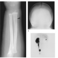
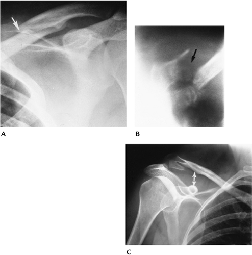 FIGURE 7-9 (A) AP radiograph of a minimally displaced fracture of the mid-clavicle (arrow). (B) AP tomogram of a medial clavicular fracture. (C) AP radiograph of a distal clavicular fracture with coracoclavicular ligament disruption (double arrow). |
Suggested Reading
Neviaser JS. The treatment of fractures of the clavicle. Surg Clin North Am 1963;43:1555–1563.
Fractures/Dislocations: Posttraumatic Osteolysis
Key Facts
Posttraumatic osteolysis occurs in the distal clavicle.
Patients present with pain and weakness.
Differential diagnosis includes rotator cuff tear and AC separation.
Routine radiographs may be normal early, but later erosive changes occur in the distal clavicle. MRI shows edema (increased signal on T2-weighted images) in the distal clavicle and joint.
When conservative therapy fails, the distal clavicle can be resected.
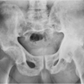
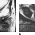
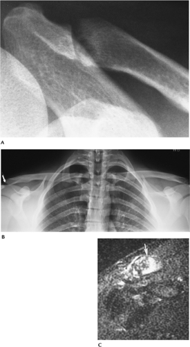 FIGURE 7-10 (A) AP radiograph shows widening of the AC joint with irregularity of the distal clavicle. (B) Stress views of the AC joints show irregularity (arrow) with no displacement. (C) T2-weighted MR image shows increased signal intensity in the distal clavicle (arrow) as the result of edema. |
Suggested Reading
Quinn SF, Glass TA. Posttraumatic osteolysis of the clavicle. South Med J 1983;76:307.
Fractures/Dislocations: Scapular Fractures
Key Facts
Fractures of the scapula are uncommon (1% of all skeletal fractures).
Injury is the result of direct trauma.
Scapular fractures can be overlooked on AP and lateral radiographs.
Associated fractures of the clavicle and ribs occur in 88%.
Articular involvement is best evaluated with CT.
Conservative therapy usually is preferred unless there is significant articular deformity or displacement.
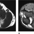
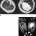
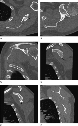 FIGURE 7-11 Scapular fracture. Axial (A,B), coronal (C), and sagittal (D–F) CT images demonstrate a fracture of the scapular wing involving the spine (open arrow) and glenoid neck (arrow), but sparing the articular surface.
Related posts:Stay updated, free articles. Join our Telegram channel
Full access? Get Clinical Tree
 Get Clinical Tree app for offline access

|