Spine
Thomas H. Berquist
Douglas S. Fenton
Protocols
Key Facts
| |
| Trauma/routine | Anteroposterior (AP), lateral, AP odontoid, both obliques (must see C7–T1) |
| Special | Swimmer’s view for cervicothoracic junction Flexion/extension for instability |
| Thoracic spine | AP and lateral views |
| |
| Routine | |
| AP, lateral, coned-down lateral | |
| Additional views | Both obliques (pars defects) |
| Flexion-extension | For instability and motion |
| Lateral bending | Motion, curve flexibility in scoliosis |
| |
| Coils | Phased array, multicoil arrays |
| Field of view (FOV) | 16 to 24 cm |
| Matrix | 256 × 256 or 192 × 256 |
| Acquisitions | 1 |
| Pulse sequences | Section Thickness/Skip | FOV | Matrix | Acquisitions |
|---|---|---|---|---|
| Cervical spine—routine | ||||
| Sagittal spin echo (SE) 400/16 | 3.5/0.5 mm | 22-cm FOV | 256 × 192 | 3 |
| Sagittal fast-spin echo (FSE) 3275/105 | 3.5/0.5 mm | 22-cm FOV | 256 × 256 | 4 |
| Axial gradient-recalled echo 400/7, 20 degrees | 4 mm | 20-cm FOV | 256 × 192 | 2 |
| Thoracic spine | ||||
| Sagittal SE 475/16 | 3.5/0.5 mm | 28-cm FOV | 256 × 256 | 2 |
| Sagittal FSE 2800/105 | 3.5/0.5 mm | 28-cm FOV | 256 × 256 | 4 |
| Axial gradient-recalled echo 350/17, 20 degrees | 4 mm | 20-cm FOV | 256 × 192 | 4 |
| Lumbar spine | ||||
| Sagittal SE 475/16 | 4/1 mm | 28-cm FOV | 256 × 256 | 2 |
| Sagittal FSE 2800/102 | 4/1 mm | 28-cm FOV | 256 × 256 | 4 |
| Axial SE 470/17 | 5 mm | 18-cm FOV | 256 × 192 | 2 |
| Axial FSE 2800/105 | 5 mm | 18-cm FOV | 256 × 256 | 3 |
| Multilevel | ||||
| Sagittal SE 500/16 | 3.5/0.5 | 48-cm FOV | 512 × 512 | 2 |
| Sagittal FSE 3000/105 | 3.5/0.5 | 22-cm FOV | 256 × 256 | 2 |
Suggested Reading
Daffner RH. Cervical radiography for trauma patients. A time effective technique. AJR Am J Roentgenol 2000;175:1309–1311.
Wintermark M, Moushine E, Theumann N, et al. Thoracolumbar spine fractures in patients who have sustained severe trauma: Depiction with multidetector row CT. Radiology 2003;227:681–689.
Witte RJ, Lane JI, Miller GM, et al. Spine. In: Berquist TH, ed. MRI of the musculoskeletal system, 5th ed. Philadelphia: Lippincott Williams & Wilkins; 2006:121–202.
Trauma: Cervical Spine—Basic Concepts
Key Facts
Approximately 65% of spinal injuries involve the cervical spine. The average number of injuries per patient is 2.2.
The incidence of cervical spine injury after blunt trauma is 2% to 6%.
The cervical spine should remain immobilized until the patient has been cleared (no injury) or until the extent of injury has been determined.
Ninety percent of significant injuries are detectable on the lateral view.
Patients with altered mental status, posterior midline tenderness, or neurologic deficit undergo CT in addition to radiographs. CT has approximately a 100% sensitivity for detection of fractures compared with 65% for radiographs.
Understanding the mechanism of injury is helpful for evaluating images and determining prognosis (Table 3-1).
Stability of injuries is important to assess. This usually can be accomplished on the lateral view or reformatted CT images, although all images should be assessed.
TABLE 3-1 CERVICAL SPINE TRAUMA: MECHANISMS OF INJURY
Type of Injury
Radiographic Features
Comments
Hyperflexion
Most common
Disruptive hyperflexion
Sprain, transient dislocation
Locked facets
Spinous process fractures
Compressive hyperflexion
Vertebral wedge fractures
Teardrop fractures
Fracture/dislocations
Shearing injuries
Anteriorly displaced odontoid fractures
Hyperextension
Findings may be subtle
Disruptive hyperextension
Hangman’s fractures
Hyperextension sprain
Anterior inferior body fractures
Compressive hyperextension
Posterior arch fractures
Hyperextension fracture/dislocation
Shearing
Posteriorly displaced odontoid fractures
Axial compression
Jefferson fractures
Burst fractures
Flexion-rotation
Rotary fixation of C1 on C2
Unilateral locked/perched facets
Lateral flexion
Uncinate process fractures
Transverse process fractures
Lateral wedge fractures
Indicators of instability include
More than one column involved (Fig. 3-7)
Subluxation greater than 3 mm
Increased interspinous distance
Facet joint widening
Narrowed disc or widened space
Vertebral compression greater than 25%
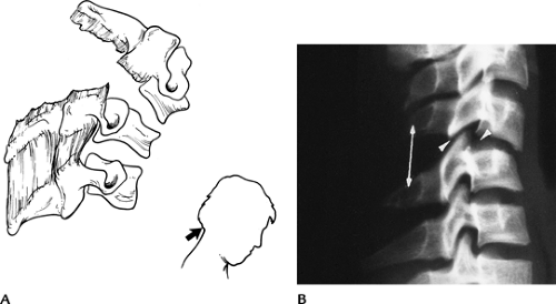 FIGURE 3-1 Disruptive hyperflexion injuries. (A) Mechanism (blow to the occipital region) that causes more posterior soft tissue injury compared with anterior compression. (B) Lateral radiograph shows widened interspinous distance (double arrow), subluxation of the facets (posterior arrowhead) and slight subluxation, and disc space widening (anterior arrowhead). |
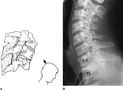 FIGURE 3-2 Compressive hyperflexion injuries. (A) Mechanism of injury with force transmitted to the anterior vertebral body. (B) Lateral radiograph demonstrates compression of C7 and T1 (arrow). |
 FIGURE 3-3 Disruptive hyperextension injuries. (A) Disruptive hyperextension injury with anterior distraction. The cord may be compressed. (B) Lateral radiograph shows anterior disc space widening and vertebral chip fracture (arrow). |
 FIGURE 3-4 Compressive hyperextension injuries. (A) Mechanism resulting in posterior compression and less anterior distraction. (B) Lateral radiograph demonstrating a vertical posterior arch fracture (arrow). |
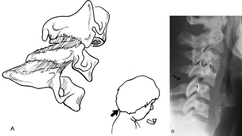 FIGURE 3-5 Flexion-rotation injuries. (A) Mechanism of injury. (B) Lateral radiograph shows a unilateral locked facet with subluxation and “bow-tie” configuration (lines) of the facets. |
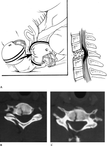 FIGURE 3-6 Vertical compression injuries. (A) Mechanism of injury. (B,C) Axial CT images of a burst fracture. |
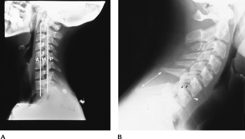 FIGURE 3-7 Instability. (A) Lateral radiograph demonstrating the anterior (anterior longitudinal ligament, body, and disc), middle (posterior body and disc and posterior longitudinal ligament), and posterior (facet joints and posterior ligaments) columns. When two columns are involved the injury should be considered unstable. (B) Lateral view showing multiple column involvement with widened interspinous distance (double arrow), subluxation (black lines), and anterior disc space narrowing (arrowhead) caused by a disruptive hyperflexion injury. |
Suggested Reading
Denis F. Spinal instability as defined by the three column spine concept in acute spinal trauma. Clin Orthop 1984;189:65–76.
Gehweiler JA, Osborne RL, Becker RF. The radiology of the vertebral trauma. Philadelphia: WB Saunders; 1980.
Griffen MM, Frykberg ER, Kerwin AJ, et al. Radiographic clearance of blunt cervical spine injury: Plain radiograph or computed tomography scans. J Trauma 2003;55:222–227.
Sliker CW, Mirvis SE, Shanmuganathan K. Assessing cervical spine stability in obtunded blunt trauma patients: Review of the medical literature. Radiology 2005;234:733–739.
Trauma: Cervical Spine—Atlanto-Occipital Fracture Dislocations
Key Facts
Atlanto-occipital dislocations usually are fatal; therefore, imaging is rarely performed.
The injury results from high-velocity shearing forces dislocating the head from C1.
In children, the condyles are less well developed, making patients more susceptible to injury.
If the patient survives the injury, treatment is occipital-C2 fusion.
 FIGURE 3-8 Atlanto-occipital dislocation. Lateral radiograph shows a huge prevertebral hematoma (arrows) with anterior dislocation of the occipital condyles (arrowhead). The patient did not survive. |
Suggested Reading
Deliganis AV, Baxter AB, Hanson JA, et al. Radiologic spectrum of craniocervical distraction injuries. Radiographics 2000;20:S237–S250.
Hosalkar HS, Cain EL, Chin KR, et al. Traumatic atlanto-occipital dislocation in children. J Bone Joint Surg 2005;87A:2480–2488.
Trauma: Cervical Spine—C1 Fractures
Key Facts
Fractures of the atlas (C1) account for approximately 4% to 10% of all spinal injuries.
Five types of fracture typically occur.
Anterior arch—hyperextension
Posterior arch (67%)—hyperextension
Lateral mass—vertical compression
Transverse process—lateral flexion
Jefferson fracture—vertical compression
Associated injuries include
Hangman’s fractures (15%)
C7 spinous process fractures (26%)
Other lower cervical fractures (22%)
Neurologic injury is unusual, because the anatomy and mechanism of injury force the fragments away from the spinal canal.
Imaging is accomplished with lateral and open-mouth odontoid views. CT is preferred for complete evaluation.
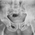
 FIGURE 3-9 Jefferson fracture. (A) Mechanism of injury for Jefferson fractures. (B) AP open-mouth odontoid view shows displacement of the lateral masses outward (arrows). (C) The extent of injury is best appreciated on the axial CT image. |
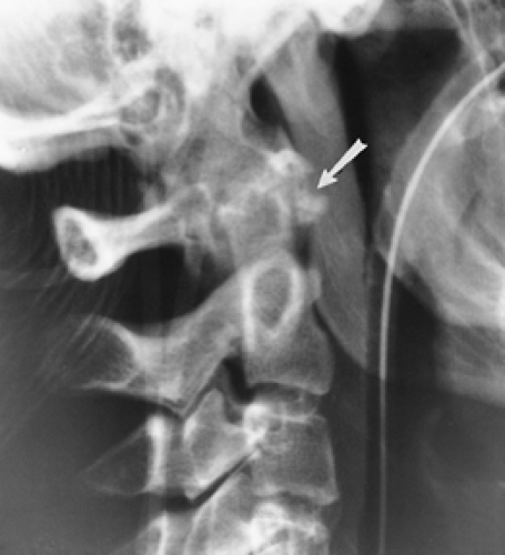 FIGURE 3-10 Hyperextension injury C1. Lateral radiograph of the upper cervical spine demonstrates an avulsion fracture of the anterior arch of C1 (arrow). |
Suggested Reading
Harris JH, Mirvis SE. The radiology of acute cervical spine trauma. 3rd ed. Baltimore: Williams and Wilkins; 1996:340–366.
Jackson RS, Banit DM, Rhyne AL, et al. Upper cervical spine injuries. J Am Acad Orthop Surg 2002;10:271–280.
Trauma: Cervical Spine—Atlantoaxial Dislocations
Key Facts
Traumatic dislocations of the atlantoaxial axis are rare.
The transverse ligament assists in maintaining the normal C1–2 relationship. Subluxations may occur with conditions that affect the normal osseous or ligamentous integrity (rheumatoid arthritis, retropharyngeal infection, congenital abnormalities, trauma).
Traumatic subluxation/dislocation may be anterior, posterior, or rotary in nature.
Normally, the space between the odontoid and lower anterior arch of C1 is 2 mm in adults and 4 mm in children.
Imaging can be accomplished with lateral and open-mouth odontoid views. However, thin-section CT with reformatting or three-dimensional reconstruction is most accurate for detection and classification.
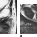
 FIGURE 3-11 (A) Lateral radiograph of the upper cervical spine demonstrates anterior subluxation of C1 on C2. Odontoid-C1 and posterior arch relationships (dotted lines). (B) Axial CT image demonstrates an anterior arch fracture (arrow) and avulsion (arrowhead) of the transverse ligament. |
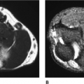
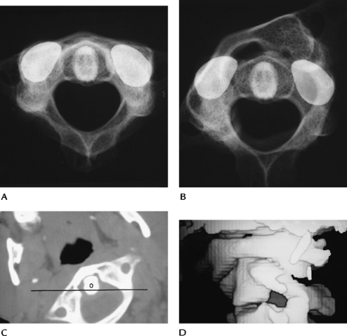 FIGURE 3-12 Rotary subluxation/fixation. Skeletal specimens with metal markers on the C2 facet demonstrating normal (A) and rotary fixation (B) of C1 on C2. Axial (C) and three-dimensional reconstruction images (D) show rotary fixation. The position of C2 (line). O, odontoid. |
Suggested Reading
Fielding JW, Hawkins RJ. Atlantoaxial rotary fixation. J Bone Joint Surg 1977;57A:37–44.
Neumann U, Urbanski H, Riedel K. Posterior atlantoaxial dislocation without fracture of the odontoid. J Bone Joint Surg 2003;85A:1343–1346.
Trauma: Cervical Spine—Axis (C2)
Key Facts
Fractures of C2 are common, accounting for 15% to 27% of cervical spine injuries (Table 3-2). Up to 25% have associated lower cervical fractures. Odontoid fractures account for 75% of cervical spine injuries in children.
Fractures of the odontoid and neural arch (hangman’s fracture) account for 80% of C2 fractures.
Odontoid fractures may be subtle, and up to 25% of fractures can be missed unless reformatted (coronal and sagittal) CT images are obtained.
Odontoid fractures are classified by location (Table 3-3). Fractures of the base of the odontoid (Type II) have a high incidence of nonunion (54%–67%) and instability.
Hangman’s fractures (neural arch) are hyperextension injuries. Ten percent experience transient neurologic deficits.
Fractures of the body, lamina, and spinous processes of C2 occur less frequently.
Lateral radiographs usually identify the abnormality, with the exception of undisplaced odontoid fractures. CT with reformatted sagittal images is essential in these patients.
TABLE 3-2 AXIS (C2) FRACTURES | ||||||||||
|---|---|---|---|---|---|---|---|---|---|---|
|
TABLE 3-3 ODONTOID FRACTURE CLASSIFICATION | ||||||||||||
|---|---|---|---|---|---|---|---|---|---|---|---|---|
|
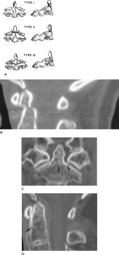 FIGURE 3-13 (A) Odontoid fracture classification: Type I—odontoid tip; Type II—odontoid base, above accessory ligament and vascular supply (arrows); and Type III—extend into body below vascular supply. (B) Sagittal reformatted CT image of a Type II odontoid fracture not evident on radiographs. Coronal (C) and sagittal (D) reformatted CT images of a Type III odontoid fracture (arrows). |
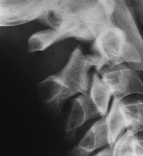 FIGURE 3-14 Hangman’s fracture with displacement of C2 on C3. |
 FIGURE 3-15 Anterior inferior body fracture of C2 (arrow). |
Suggested Reading
Berquist TH. Imaging of orthopedic trauma. 2nd ed. New York: Raven Press; 1992:93–206.
Jackson RS, Banit DM, Rhyne AL, et al. Upper cervical spine injuries. J Acad Orthop Surg 2002;10:271–280.
Trauma: Cervical Spine—Lower Cervical Spine: Vertebral Arch Fractures
Key Facts
Vertebral arch fractures most frequently are the result of hyperextension or lateral flexion injuries. Common sites and incidences in our experience are as follows:
• Lamina
28%
• Pedicle
25%
• Spinous process
22%
• Pillar
16%
• Facets
9%
• Transverse process
2%
• (Multiple injuries result in total >100%)
Laminar fractures are commonly associated with spinous process fractures. The majority occur from C5–7.
Pedicle fractures may occur at C2 (hangman’s) or in the lower cervical spine. If undisplaced, they may be easily overlooked on routine radiographs.
Spinous process fractures are most common from C5–T1. Injury may be the result of direct trauma, hyperextension, or hyperflexion.
Pillar fractures without displacement may be overlooked on radiographs. They are most common at C6.
Facet fractures are the result of flexion-rotation or hyperflexion injuries.
Transverse process fractures occur with direct trauma or lateral flexion.
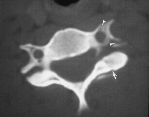 FIGURE 3-16 CT image of a facet fracture (arrow). There is also a fracture through the foramen transversarium (arrowheads). |
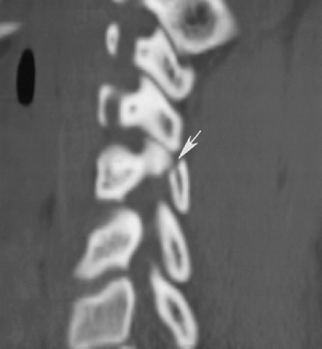 FIGURE 3-17 Sagittal CT image of a C5 facet fracture (arrow). |
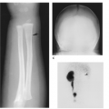
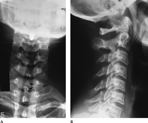 FIGURE 3-18 Spinous process fracture at C7 (Clay shoveler’s fracture). (A) AP view shows a double spinous process (arrows). This is a helpful sign as the lower cervical spine is often difficult to visualize on the lateral view. (B) Lateral view shows the C7 spinous process fracture clearly in this case. |
Suggested Reading
Berquist TH. Imaging of adult cervical spine trauma. Radiographics 1988;8:667–694.
Harris JH, Mirvis SE. The radiology of acute cervical spine trauma. 3rd ed. Baltimore: Williams and Wilkins; 1996:408–419.
Trauma: Cervical Spine—Lower Cervical Spine: Vertebral Body Fractures
Key Facts
More than 31% of cervical spine injuries involve the vertebral body. Seventy-five percent of fractures occur from C5–7.
Routine radiographs have 65% to 90% sensitivity for fracture detection. However, CT is required for the evaluation of subtle injuries, the spinal canal, and the fragment position.
Table 3-4 summarizes vertebral body fractures.
TABLE 3-4 VERTEBRAL BODY FRACTURES | |||||||||||||||||||||||
|---|---|---|---|---|---|---|---|---|---|---|---|---|---|---|---|---|---|---|---|---|---|---|---|
| |||||||||||||||||||||||
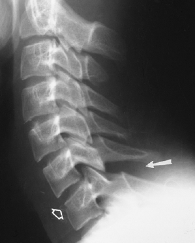 FIGURE 3-19 Flexion compression injury with compression of C7 and an anterior chip fracture (open arrow). There is widening of the interspinous distance (arrow) indicating posterior ligament injury and instability. |
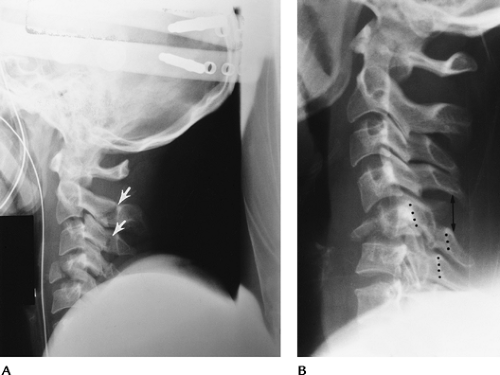 FIGURE 3-20 Teardrop fractures. (A) Hyperextension teardrop of C4. Note the posterior arch fractures of C2 and C3 (arrows) indicating the mechanism of injury. (B) Hyperflexion teardrop fracture of C5 with compromise of the spinal canal (dotted lines) and posterior ligament tears (double arrow). |
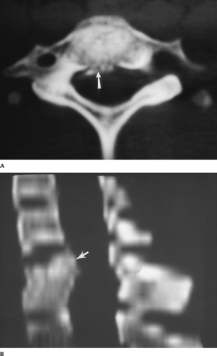 FIGURE 3-21 Burst fracture. Axial (A) and reformatted sagittal (B) CT images show the fragments (arrow) and narrowing of the spinal canal. |
Suggested Reading
Berquist TH. Imaging of orthopedic trauma. 2nd ed. New York: Raven Press; 1992:93–206.
Sanchez B, Waxmann K, Jones T, et al. Cervical spine clearance in blunt trauma: Evaluation of a computed tomography-based protocol. J Trauma 2005;59:179–183.
Trauma: Cervical Spine—Lower Cervical Spine: Subluxation, Fracture/Dislocation
Key Facts
Most significant ligament injuries involve the posterior column. Seventy-three percent occur at the C5–7 levels. Anterior ligament injuries are most common at C2–4 and C6–7. Ligament injuries may occur alone or with fractures.
The spectrum of injuries may be subtle, without obvious abnormality and normal bony alignment, or injuries may be grossly obvious, such as bilateral locked facets.
Unilateral facet locking or perching may present with subtle radiographic findings. This flexion-rotation injury accounts for 12% of cervical injuries. Reformatted CT imaging is often required for detection and complete evaluation of these injuries.
Imaging of subluxation can be accomplished with routine radiographs and CT. Flexion and extension views can be performed to assess stability, but they should be monitored fluoroscopically. In the acute setting, false-negative results are not unusual the result of muscle splinting.
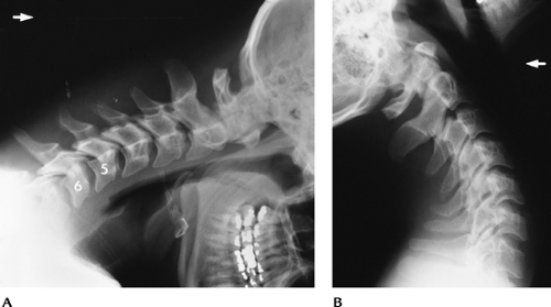 FIGURE 3-22 Flexion distraction injury with posterior ligament tear at C5–C6. Flexion (A) and extension (B) views show subluxation and widening of the interspinous distance and facet joints with flexion that reduces with extension. Treatment-posterior fusion. |
 FIGURE 3-23 Unilateral locked facet. (A) AP radiograph shows disc space asymmetry (arrow) at C4–C5 and rotation of the spinous process. (B) Lateral view shows subluxation, and the C4 facets form the “bow-tie” sign. (C) Oblique view shows the facet overlap (arrow).
Related posts:Stay updated, free articles. Join our Telegram channel
Full access? Get Clinical Tree
 Get Clinical Tree app for offline access

|