- Only request an examination if it is likely to affect patient management
- The time interval between follow-up examinations should be appropriate and depends on the natural history of disease
- Localize the clinical problem as specifically as possible prior to imaging in order to reduce over-investigation and excess radiation exposure
- Careful consideration should be given to which imaging procedure is likely to give the relevant diagnostic information most easily
- Any investigations that have been requested but become unnecessary should be cancelled
- Examinations that minimize or avoid ionizing radiation should be chosen when possible
- Good communication with the radiologists is key to ensuring appropriate investigation pathways
Conventional Radiography
X-rays are absorbed to a variable extent as they pass through the body. The visibility of both normal structures and disease depends on this differential absorption. With conventional radiography there are four basic densities – gas, fat, all other soft tissues and calcified structures. X-rays that pass through air are least absorbed and, therefore, cause the most blackening of the radiograph, whereas calcium absorbs the most and so the bones and other calcified structures appear virtually white. The soft tissues, with the exception of fat, e.g. the solid viscera, muscle, blood, a variety of fluids, bowel wall, etc., all have similar absorptive capacity and appear the same shade of grey on conventional radiographs. Fat absorbs slightly fewer x-rays and, therefore, appears a little blacker than the other soft tissues. Traditionally, images were produced using a silver-based photographic emulsion but now they are recorded digitally and viewed on computer screens in most centres.
Projections are usually described by the path of the x-ray beam. Thus, the term PA (posteroanterior) view designates that the beam passes from the back to the front, the standard projection for a routine chest film. An AP (anteroposterior) view is taken from the front. The term ‘frontal’ refers to either PA or AP projection. The image on an x-ray film is two-dimensional. All the structures along the path of the beam are projected on to the same portion of the film. Therefore, it is often necessary to take at least two views to gain information about the third dimension. These two views are usually at right angles to one another, e.g. the PA and lateral chest film. Sometimes two views at right angles are not appropriate and oblique views are substituted.
Portable x-ray machines can be used to take films of patients on the ward or in the operating theatre. Such machines have limitations on the exposures they can achieve. This usually means longer exposure times and poorer quality films. The positioning and radiation protection of patients in bed is often inferior to that which can be achieved within the x-ray department. Consequently, portable films should only be requested when the patient cannot be moved safely to the x-ray department.
Computed Tomography
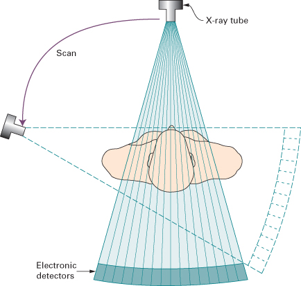
Computed tomography (CT) also relies on x-rays transmitted through the body. It differs from conventional radiography in that a more sensitive x-ray detection system is used, the images consist of sections (slices) through the body, and the data are manipulated by a computer. The x-ray tube and detectors rotate around the patient (Fig. 1.1). The outstanding feature of CT is that very small differences in x-ray absorption values can be visualized. Compared with conventional radiography, the range of densities recorded is increased approximately ten-fold. Not only can fat be distinguished from other soft tissues, but also gradations of density within soft tissues can be recognized, e.g. brain substance from cerebrospinal fluid, or tumour from surrounding normal tissues.
Fig. 1.1 Principle of CT. The x-ray tube and detectors move around the patient enabling a picture of x-ray absorption in different parts of the body to be built up.
The patient lies with the body part to be examined within the gantry housing the x-ray tube and detectors. Although other planes are sometimes practicable, axial sections are by far the most frequent. The operator selects the level and thickness to be imaged: the usual thickness is between 1.25 and 2 mm (often viewed by aggregating adjacent sections so they become 5 mm thick). The patient is moved past an array of detectors within the machine. In effect, the data at multiple adjacent levels are collected continuously, during which time the x-ray beam traces a spiral path to create a ‘volume of data’ within the computer memory. Multidetector (multislice) CT acquires multiple slices (64, 128, 256 or 320 depending on the machine) during one rotation of the x-ray tube. Multidetector CT enables the examination to be performed in a few seconds, thereby enabling hundreds of thin sections to be obtained in one breath-hold. A relatively new development is dual source (or dual energy) CT. This technique allows a virtual non-contrast CT image to be derived from CT acquired with intravenous iodinated contrast medium (see later in chapter) allowing a reduction in radiation dose in certain CT protocols.
The data obtained from the multislice CT exposures are reconstructed into an image by computer manipulation. The computer calculates the attenuation (absorption) value of each picture element (pixel). Each pixel is 0.25–0.6 mm in diameter, depending on the resolution of the machine, with a height corresponding to the chosen section thickness. The resulting images are displayed on a monitor and can be stored electronically. The attenuation values are expressed on an arbitrary scale (Hounsfield units) with water density being zero, air density being minus 1000 units and bone density being plus 1000 units (Fig. 1.2). The range and level of densities to be displayed can be selected by controls on the computer. The range of densities visualized on a particular image is known as the window width and the mean level as the window level or window centre. CT is usually performed in the axial plane, but because attenuation values for every pixel are present in the computer memory it is possible to reconstruct excellent images in other planes, e.g. coronal (Fig. 1.3), sagittal or oblique, and even three-dimensional (3D) images (Fig. 1.4).
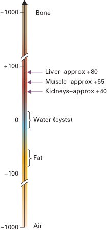
Fig. 1.3 Coronal reconstruction of CT of the chest, abdomen and pelvis. The images were obtained in the axial plane using very thin sections and then reconstructed into the desired plane – a coronal plane in this example. The illustrated section is through the posterior abdomen and shows the kidneys. There is a retroperitoneal mass (arrow) displacing the left kidney and causing hydronephrosis.
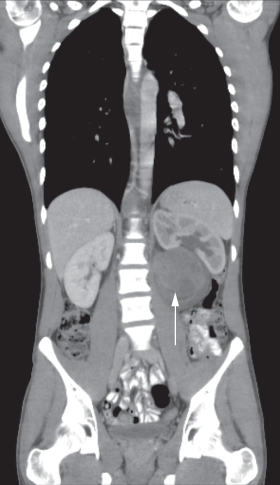
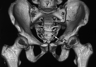
Fig. 1.4 Shaded surface 3D CT reconstruction. The images can be viewed in any desired projection and give a better appreciation of the pelvis. Two fractures are demonstrated in the left innominate bone (arrows), which were hard to diagnose on plain film.
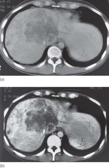
The human eye can only appreciate a limited number of shades of grey. With a wide window all the structures are visible, but fine details of density difference cannot be appreciated. With a narrow window width, variations of just a few Hounsfield units can be seen, but much of the image is either totally black or totally white and in these areas no useful information is provided. The effects of varying window width and level are illustrated in Figs 1.5 and 2.6.
Fig. 1.5 Effect of varying window width on CT. In (a) and (b) the level has been kept constant at 65 Hounsfield units (HU). The window width in (a) is 500 HU whereas in (b) it is only 150 HU. Note that in the narrow window image (b), the metastases are better seen, but that structures other than the liver are better seen in (a).
Computed Tomography Angiography
Rapid intravenous injections of contrast media result in significant opacification of blood vessels, which, with multiplanar or 3D reconstructions, can be exploited to produce angiograms. CT angiography, along with magnetic resonance angiography, is gradually replacing conventional diagnostic angiography.
Artefacts
There are numerous CT artefacts. The most frequent are those produced by movement and those from objects of very high density, such as barium in the bowel, metal implants, dental fillings or surgical clips. Both types give rise to radiating linear streaks. The major problem is the resulting degradation of the image.
Contrast Agents in Conventional Radiography and Computed Tomography
Radiographic contrast agents are used to visualize structures or disease processes that would otherwise be invisible or difficult to see. Barium is widely used to outline the gastrointestinal tract on conventional radiographic images; all the other radio-opaque media rely on iodine in solution to absorb x-rays. Iodine-containing solutions are used for urography, angiography and intravenous contrast enhancement at CT. Usually they are given in large doses, often with rapid rates of injection. As their only purpose is to produce opacification, ideally they should be pharmacologically inert. This has not yet been totally achieved, though the current low osmolality, non-ionic contrast media have exceedingly low complication rates.
Some patients experience a feeling of warmth spreading over the body as the iodinated contrast medium is injected. Contrast inadvertently injected outside the vein is painful and should be carefully guarded against. A few patients develop an urticarial rash, which usually subsides spontaneously.
Bronchospasm, laryngeal oedema or hypotension occasionally develop and may be so severe as to be life-threatening. It is therefore essential to be prepared for these dangerous reactions and to have available appropriate resuscitation equipment and drugs. Patients with known allergic manifestations, particularly asthma, are more likely to have an adverse reaction. Similarly, patients who have had a previous reaction to contrast agents have a higher than average risk of problems during the examination and an alternative method of imaging should be considered. Patients at higher risk are observed following the procedure. Intravenous contrast agents may have a deleterious effect on renal function in patients with impaired kidneys. Therefore, their use should be considered carefully on an individual basis and the patient should be well hydrated prior to injection.
Ultrasound
In diagnostic ultrasound examinations, very high frequency sound is directed into the body from a transducer placed in contact with the skin. In order to make good acoustic contact, the skin is smeared with a jelly-like substance. As the sound travels through the body, it is reflected by the tissue interfaces to produce echoes which are picked up by the same transducer and converted into an electrical signal.
As air, bone and other heavily calcified materials absorb nearly all the ultrasound beam, ultrasound plays little part in the diagnosis of lung or bone disease. The information from abdominal examinations may be significantly impaired by gas in the bowel, which interferes with the transmission of sound.
Fluid is a good conductor of sound, and ultrasound is, therefore, a particularly good imaging modality for diagnosing cysts, examining fluid-filled structures such as the bladder and biliary system, and demonstrating the fetus in its amniotic sac. Ultrasound can also be used to demonstrate solid structures that have a different acoustic impedance to adjacent normal tissues, e.g. metastases.
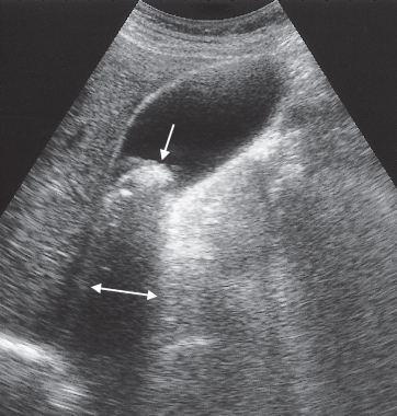
Ultrasound is often used to determine whether a structure is solid or cystic (Fig. 1.6). Cysts or other fluid-filled structures produce echoes from their walls but no echoes from the fluid contained within them. Also, more echoes than usual are received from the tissues behind the cyst, an effect known as acoustic enhancement. Conversely, with a calcified structure, e.g. a gall stone (Fig. 1.7), there is a great reduction in the sound that will pass through, so a band of reduced echoes, referred to as an acoustic shadow, is seen behind the stone.
Fig. 1.6 Ultrasound scan of longitudinal section through the liver and right kidney. A cyst (C) is present in the upper pole of the kidney.
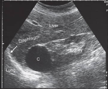
Fig. 1.7 Ultrasound scan of gall bladder showing a large stone in the neck of the gall bladder (downward pointing arrow). Note the acoustic shadow behind the stone (horizontal double-headed arrow).
Related posts:
Stay updated, free articles. Join our Telegram channel

Full access? Get Clinical Tree


