Fig. 3.1
A modern cylindrical 1.5-T whole-body MR imager (Magnetom Aera, Siemens Healthcare Sector, Erlangen, Germany)
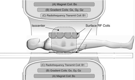
Fig. 3.2
Longitudinal diagram of a cylindrical MR imager. The housing typically contains three types of coil systems (from the outside to the inside): (A) the magnet coil producing the scanner’s homogeneous static main magnetic field (B0) for alignment of magnetic spins; (B) a set of gradient coils to generate spatially varying gradient fields (Gx, Gy, Gz) in all three spatial dimensions for spatial encoding of the MR signal; and (C) the radiofrequency (RF) transmit coil, which generates an RF field (B1) for inducing the aligned spins inside the patient’s body to precess at Larmor frequency. The three electromagnetic coil systems (B0, Gxyz, B1) are designed to generate an optimal imaging volume in the isocenter, or center of the magnet, where the B0 and B1 fields are very uniform and the gradient fields, Gxyz, are largely linear. The RF signal response of the excited spins inside the patient is collected by one or several local RF surface coils positioned above and/or below the target anatomy. To obtain good MR images, the target anatomy must be in the isocenter of the magnet. In whole-body MRI, this can be accomplished by using a moving table: the table with the patient is advanced through the bore of the magnet to successively move different body regions into the isocenter
3.2.2 The Gradient System
Whole-body MRI also requires a high-performance gradient system, meaning that it should combine a fast slew rate (given in mT/m/ms) with a high gradient amplitude (given in mT/m). These features enable short repetition and echo times (TR and TE), which are needed for fast image acquisition and hence coverage of a large volume in a short period of time. This is an important prerequisite for whole-body MRI to achieve diagnostic image quality within clinically acceptable acquisition times. A short TR is also important to achieve maximum T1 contrast, ensuring high conspicuity of contrast-enhancing vessels against saturated static tissue in MRA. High gradient linearity over a large area is necessary to minimize image distortion, especially at the periphery of the FOV. Again, these requirements are best met if the gradient coils are cylindrical as well (Figs. 3.1 and 3.2).
3.2.3 The Radiofrequency System
The radiofrequency (RF) system should be capable of providing uniform excitation of a large imaging volume. Excitation of the entire target volume with a largely constant flip angle (FA) is crucial for the resulting image contrast. This is accomplished by using the scanner’s built-in whole-body RF coils, which are large cylindrical volume coils (Figs. 3.1 and 3.2).
Uniformity across a large volume is also required for signal readout. Here, however, signal sensitivity is somewhat more important than uniformity because it determines inherent image contrast, while nonuniformity merely degrades brightness distribution in the image. Although the large built-in whole-body RF coil ensures homogeneity across a large volume, signal readout is limited by a moderate SNR. To overcome this limitation, a variety of approaches using RF surface coils have been employed (Fig. 3.2). Surface coils are placed directly on or over the target anatomy and selectively receive signal from nearby tissue. This spatially selective sensitivity improves signal detection from the body part of interest and also confines the contribution of image noise to this small region. In this way, surface coils can improve SNR, which translates into better image quality and spatial resolution. At the same time, however, the small sensitivity range is a major drawback of surface coils. To image a large volume, many coil elements arranged in a phased array are necessary. Phased-array coils combine the high SNR of a local coil with extended coverage. Utilizing the full potential of this technology requires a large number of RF receivers, to which the coil elements are connected either individually or in small groups. This is also a basic prerequisite for the use of parallel imaging techniques.
3.3 From Local to Global Imaging: Toward Stepwise Extension of the Imaging Field
3.3.1 Moving Table Platforms: SKIP, AngioSURF, and Others
The traditional imaging field of 400–500 mm is clearly too small for a comprehensive angiographic evaluation of the vascular system or for a comprehensive search for metastases. One option for extending the effective FOV is to perform imaging in a series of discrete steps, moving the scanner table between acquisitions so as to shift the position of the patient relative to the imaging field (Ho et al. 1998, 1999; Wang et al. 1998; Meaney et al. 1998; Ruehm et al. 2000a, 2000b, 2001; Leiner et al. 2000, 2004; Goyen et al. 2001; Busch et al. 2001; Huber et al. 2003). This technique, known as multistation imaging, allows step-by-step scanning of different body regions in the magnet’s isocenter, which is defined and limited by field homogeneity, gradient linearity, and RF signal excitation and readout. While the individual stations must meet the same requirements as in conventional MRI, the multistation technique extends the overall scope of the examination by enabling successive imaging of different parts of the patient’s body.
Multistation imaging requires a table moving relative to the isocenter of the magnet. The maximum table range directly determines the imaging range or how much of the patient’s body can be successively moved through the scanner’s effective FOV. The automatic patient tables of older scanners have a maximum range of less than 150 cm, which is sufficient for peripheral MRA of the pelvis and legs. For head-to-toe imaging, however, it is necessary to reposition the patient at least once between acquisitions: positioning the patient head-first for the first part of the examination and feet-first for the second part, or vice versa.
True whole-body MRI, the next step in the development, is no longer hampered by table range limitations and avoids the need for repositioning the patient during a full-body examination. Its technical implementation was made possible by important contributions from several independent study groups working in this field. The table range limitations were overcome by the advent of manually moved table platforms such as SKIP (Stepping Kinematic Imaging Platform, Magnetic Moments, Bloomfield, MI, USA) (Shetty et al. 2002) and AngioSURF (Angiographic System for Unlimited Rolling Field-of-views, MR-Innovation GmbH, Essen, Germany) (Ruehm et al. 2000a, b; Goyen et al. 2002; Winterer et al. 2003). These new platforms mark the beginning of true whole-body MRI, extending the range of motion to approx. 200 cm and enabling serial whole-body imaging in five or six stations. The problem of ensuring adequate signal readout over this extended imaging range was elegantly solved by using a stationary pair of RF coils in the isocenter of the magnet (Fig. 3.3). One coil of this pair is integrated in the patient table, contributing signal from the posterior body regions. The second coil, mounted on a coil glider, is height-adjustable and is held in position in the isocenter of the magnet by two flexible arms. This allows the coil to adjust to the body contour as the patient is being moved through the bore of the magnet for optimal signal readout from anterior body regions. The patient is positioned on an MR-compatible rolling table platform, allowing rapid and stepwise advancement of the patient through the main magnet and between the two stationary surface coils (Fig. 3.3). With this RF surface coil setup, an adequate SNR is achieved without the need for completely covering the patient’s body with surface coils. This technique has been widely used in clinical whole-body MRA (Shetty et al. 2002; Ruehm et al. 2000a, b; Goyen et al. 2002; Winterer et al. 2003; Quick et al. 2004; Herborn et al. 2004), in whole-body metastasis screening in oncologic patients (Lauenstein et al. 2002a, b; Lauenstein et al. 2004; Ghanem et al. 2004), and in MRI-based screening examinations (Ruehm et al. 2004; Goehde et al. 2005). The phased-array surface coil technology used is also suitable for performing parallel imaging to improve spatial resolution (Quick et al. 2004).
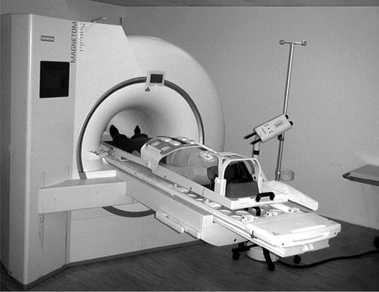
Fig. 3.3
AngioSURF table platform (MR-Innovation GmbH, Essen, Germany) mounted on top of the original patient table of a Siemens Sonata MR scanner. A patient is positioned feet first. The picture shows the table and coil positions for imaging the third of five stations; for better illustration, the table is shown moved out of the bore; during image acquisition, the height-adjustable coil glider is in the isocenter of the magnet. For a whole-body MRI examination from head to toe, five adjacent 3D datasets are sequentially acquired by moving the table platform manually between two stations, bringing the patient into the desired position for each acquisition. The table platform advances the patient between a stationary RF receive coil positioned posteriorly and a second receive coil positioned anteriorly. The latter is mounted on the coil glider, allowing it to adjust to the patient’s habitus. In this way, the distance between the patient and the readout coil is always very small, ensuring optimal SNR and image quality. A safety bar protects the patient’s face. Using the AngioSURF platform, a whole-body MRI examination can be performed quickly and with high image quality
3.3.2 RF Coils from Head to Toe and Multistation Techniques
Newer generations of MRI scanners increasingly come equipped for whole-body imaging: an automatically moving table with a range of approx. 200 cm, comprehensive solutions for covering the patient’s body with a set of dedicated phased-array RF surface coils, and a large number of independent RF receiver channels to process the signals from these coils. With this equipment, it is possible to evenly cover the patient with highly sensitive RF surface coils from head to toe for optimal signal readout from all body regions. All vendors provide their most recent machines with a variety of phased-array RF surface coils for versatile applications in different body regions. Siemens (Healthcare Sector, Erlangen, Germany), for instance, offers an RF system called Tim (Total imaging matrix), which includes up to 76 coil elements and up to 32 readout channels for a table range of 185 cm (Fig. 3.4). Tim includes a variety of dedicated RF coils, which are optimized for individual body regions and integrated into a whole-body RF system. The individual coil elements can be flexible combined with a large number of RF receivers, allowing excellent exploitation of the potential SNR. Full body coverage with RF readout coils and a table range of approx. 200 cm are the basic hardware requirements for multistation imaging, that is, automatic movement of the table for discontinuous image acquisition at a discrete number of stations (Fig. 3.5).
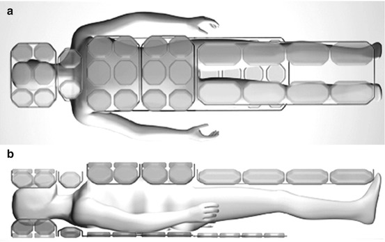
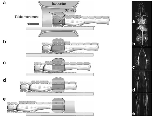
Fig. 3.4
Diagrams of the TimTM (Total imaging matrix) RF technology (Siemens Healthcare Sector, Erlangen, Germany): top view (a) and lateral view (b). The patient’s entire body can be covered with a large number of dedicated RF surface coils. The RF matrix shown in this example allows up to 76 coil elements to be connected to up to 32 independent RF receivers in different modes. Complete coverage of the patient’s body with individual RF surface coils in conjunction with motorized table movement over a range of approx. 185 cm enables whole-body image acquisition with good SNR. This technology can also be used for parallel imaging
Fig. 3.5
Multistation whole-body MRA. Longitudinal diagram of an MR imager. Following placement of RF surface coils on the patient’s body, the head/neck region is positioned in the isocenter of the magnet (a). The coronal 3D slab is positioned within the isocenter. In the course of the examination, the patient is moved through the isocenter in a stepwise fashion, from head to toe. (b–e) Multistation contrast-enhanced MRA is performed by synchronizing acquisition with the administration of the contrast medium bolus in such a way as to time the acquisition of each station with the presence of the contrast medium, chasing the bolus from the aorta to the pelvic and leg arteries and to the feet. In this way, the multistation technique enables imaging of vessels that are too long for assessment with a single conventional FOV (A–E on the right show MR angiograms acquired at each of the five stations). Multistation imaging using a moving table is the technical prerequisite for performing whole-body MRI and MRA
3.3.3 Software Requirements
In addition to the hardware developments outlined above, multistation imaging techniques would not have been possible without new software for a variety of new tasks: (1) rapid switching of RF coil elements between stations for selective signal readout by the coils at each given station; (2) acquisition of prescans (before the actual examination) to separately optimize and store parameters for each station related to tuning, shimming, specific absorption rate (SAR), and flip angle; determining these parameters before a whole-body scan is especially important in applications where the imaging window is small and timing is critical (e.g., contrast-enhanced MRA); and (3) capability for separately positioning and angling the image slab for each station and flexibly selecting spatial resolution (matrix, slice thickness). This flexibility is desirable to optimize parameters for the body part being imaged at each station and to make adjustments for differences in individual anatomy. With the new demands arising for the processing of whole-body MRI datasets, image postprocessing has also been taken from local to global. Manufacturers are increasingly offering postprocessing packages (e.g., composer tools) for virtually combining the images from the individual stations to create composite images for easier viewing and interpretation.
3.4 MRI on the Move: Continuous Table Advancement
Multistation techniques have inherent disadvantages: the time necessary for moving the table between successive acquisitions, typically 2–3 s, is not available for imaging. Additional time is lost due to redundant data acquisition, as there is generally some overlap between adjacent stations. Extra time is also needed for restoring basic magnetization. In terms of image quality, the lower signal sensitivity at the edges of individual FOVs can cause inhomogeneities in the composite images, while the geometric distortions resulting from gradient nonlinearities at the edges can cause artifacts at the interfaces of adjacent stations (Fig. 3.6). Many of these limitations impair interpretation, especially at the seams of composite images. These limitations could be overcome with a seamless whole-body 3D dataset of consistent quality that would be processed as a whole during display and interpretation.
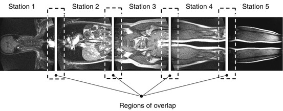
Fig. 3.6
The four or five individual datasets acquired using the multistation moving table technique are postprocessed to generate a composite whole-body image. The diagram illustrates an inherent drawback of this technique: the individual images overlap a few centimeters, meaning that there is redundancy in that approx. 10 % of the image data are acquired twice. Moreover, data acquisition needs to be interrupted to move the patient table to the next station (approx. 2 s). These two limitations reduce imaging efficiency. Finally, gradient nonlinearities at the edges of the individual FOVs can cause discontinuity artifacts at the interfaces of adjacent stations
Related posts:

Stay updated, free articles. Join our Telegram channel

Full access? Get Clinical Tree


