Fig. 1
Tympanostomy tubes. a Relationship of a plastic grommet to a 10 cent euro coin. b Axial CBCT image and c coronal reformatted image of the right ear shows a normally positioned grommet (arrow) centered on the anteroinferior part of the pars tensa. d Axial and coronal e CBCT image of the right ear demonstrates an anteromedially displaced grommet (arrow). Note the myringotomy site (arrowhead in e). f Axial and coronal g CBCT image of the left ear shows a laterally displaced grommet (arrow) lying against the tympanic membrane
The primary goal of the surgical treatment of chronic otitis media with cholesteatoma is the complete eradication of the disease (no residual disease), whereas secondary goals are the prevention of recurrent disease, the improvement of the hygienic status of the ear and the preservation or improvement of hearing (Shelton and Sheehy 1990).
Residual and recurrent cholesteatoma should not be confused. The latter is developing from recurring retraction pockets or defects in the tympanic membrane reconstruction, takes usually more time to develop and are larger at detection (Sheehy et al. 1977). Residual cholesteatoma refers to the presence of small cholesteatoma pearls that are accidently left behind at first-stage surgery. They can be found anywhere in the middle ear and/or resection cavity and are usual very small at detection during second-look surgery. In 90 % of cases, the location of the residual however is found to be that of the primary cholesteatoma. This suggests that the residual cholesteatoma is induced by insufficient local resection of the epidermal matrix. Especially residual cholesteatoma in the anterior attic is a problem in canal-wall-up (CWU) mastoidectomy. While recurrences can be diagnosed otoscopically, residual disease cannot be detected by a simple clinical examination (Venail et al. 2008) and only surgical revision can determine the diagnosis; this is the rationale behind the second-look operation (Gaillardin et al. 2012). The challenge for radiologists is to offer an imaging technique that is able to depict residual and recurrent cholesteatoma with high sensitivity and specificity, to avoid unnecessary surgery (De Foer et al. 2008, 2010).
2.1 Mastoidectomy
CT findings in the different surgical procedures performed in chronic middle ear disease including cholesteatoma have been well illustrated by Mukherji et al.; diagrams of the procedures are shown below, courtesy of the author (Mukherji et al. 1994). Surgical procedures for cholesteatoma can be broadly classified as closed cavity or canal-wall-up (CWU) mastoidectomy/tympanoplasty or open cavity or canal-wall-down (CWD) mastoidectomy depending on whether the posterior wall of the external auditory canal (EAC) is preserved. The choice of technique is usually determined by the extent of the disease and the experience and personal preferences of the surgeon (Majithia et al. 2012; Ayache et al. 2012). Defining the true extent of cholesteatoma and staging disease using non-EPI DWI can help the surgeon with his choice of surgery and surgical approach (Majithia et al. 2012). Both types of procedure have their advantages and disadvantages (Khemani et al. 2011). When possible, CWU is the procedure of choice for the treatment of cholesteatoma for most otologic surgeons (Brackmann 1993). CWU techniques preserve the anatomy of the posterior canal wall, eliminating the need for periodic bowl cleaning and avoiding the risk of recurrent bowl infections. The mastoid air cells including Koerner’s septum are removed. In this manner, communication of the surgically created cavity (mastoid bowl) with the antrum and epitympanum is established (Fig. 2). A major disadvantage of CWU procedures is less wide surgical exposure with a subsequent higher rate of residual (35 %) and recurrent (18 %) cholesteatomas (Stasolla et al. 2004). In children, these percentages may be even higher as a more aggressive behaviour of cholesteatomas is observed. Another disadvantage of CWU mastoidectomy is the limited possibility of clinical and otoscopical evaluation. This is why some institutions promote a more rigorous follow-up and a rapid second-look surgery (Plouin-Gaudon et al. 2010a). In case of CWD mastoidectomy, the posterosuperior wall of the EAC is removed, allowing communication between the mastoid cavity and the EAC. Further access to the middle ear cavity is created, depending on the extent of disease encountered. If disease is limited to the epitympanum, only the scutum needs to be resected and the ossicular chain can be preserved (Fig. 3). When the ossicular chain is involved in the disease process, a radical mastoidectomy is performed. The tympanic membrane is detached from its annulus and the mastoid segment of the facial nerve canal is skeletonised allowing wide access to the middle ear cavity (Fig. 4). However, the stapes superstructure is left in place whenever possible. Complete posterior canal wall removal provides exposure of the entire attic and middle ear, helping to ensure complete disease eradication. This approach can reduce the residual and recurrence rate to as low as 2 %. The CWD procedure is nowadays preserved for repeatedly recurrent disease with difficult to treat cholesteatoma and for patients with high risk of getting lost in follow-up. A major disadvantage of the CWD technique is the accumulation of debris in the exteriorised mastoid cavity, requiring periodic cleaning and, on occasion, water restrictions to prevent bowel infections. The CWD technique also provides for removal of the nitrogen-absorbing mucosa of the mastoid. After surgery, the new epithelial lining of the mastoid bowl is a stratified keratinizing epithelium. In the CWU procedure, the mastoid retains its native cuboidal nitrogen-absorbing epithelium. Eustachian tube dysfunction could result in reaccumulation of secretory middle ear effusion and retraction of the posterior superior quadrant of the tympanic membrane, causing recurrent cholesteatoma (Gantz et al. 2005). In order to avoid this problem, a bony obliteration technique has been advocated. The advantages of the procedure include providing increased intraoperative exposure (similar to a CWD technique), removal and obliteration of the nitrogen absorbing mastoid epithelium with bone pâté, and reconstruction of the posterior canal wall. The procedure is designed to prevent development of post-operative retraction pockets and recurrences by obliterating the mastoid cavity and isolating the tympanum from the attic and mastoid using bone chips and bone pâté (Mercke 1987). Although primary bony obliteration provides excellent results with low recurrence rates, it also carries with it the risk of obliterating and obscuring residual cholesteatomas. Follow-up by means of imaging using non-EPI DWI MRI is mandatory to prevent late complications after possible obliteration of residual cholesteatomas (De Foer et al. 2007, 2010).
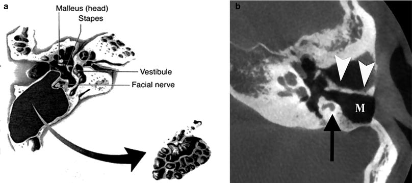
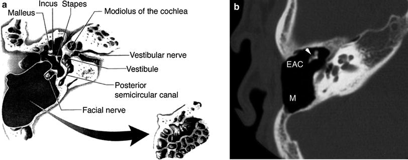
Fig. 2
Canal-wall-up (CWU) mastoidectomy. a Diagram shows removal of the mastoid air cells with preservation of the posterior wall of the right external auditory canal (EAC). (From Mukherji et al. 1994. With permission). b Axial CBCT image demonstrating CWU mastoidectomy defect (M) in the left ear. The posterior wall of the EAC is preserved (arrowheads). Note the position of the mastoid segment of the facial nerve canal (arrow)
Fig. 3
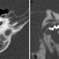
Canal-wall-down (CWD) mastoidectomy with ossicular preservation. a Diagram shows resection of both the mastoid air cells and posterior wall of the EAC at the right side. The ossicles are preserved in this procedure. (From Mukherji et al. 1994. With permission) b Axial multidetector CT (MDCT) image at the level of the mesotympanum shows the postoperative mastoid bowl (M), with preservation of the ossicles (arrowhead). In contrast with canal-wall-up mastoidectomy, the posterior wall of the EAC has been resected. Ossicular reconstruction was not required in this case
Fig. 4
Canal-wall-down mastoidectomy with removal of malleus and incus. a Diagram shows exenteration of the mastoid air cells, posterior wall of EAC, malleus and incus. The stapes superstructure is preserved. (From Mukherji et al. 1994. With permission). b Double-oblique reformatted and coronal (c) CBCT image of the right ear shows a CWD mastoidectomy defect with communication between the EAC and mastoid (M). The tympanic membrane graft (arrowhead) is located on the stapes capitulum (type III tympanoplasty)
2.2 Tympanoplasty: Ossicular Reconstruction
Tympanoplasty is a technique to reconstruct the conductive hearing system, i.e. the tympanic membrane and/or the ossicles. Five types of tympanoplasty have been defined by Wullstein (Swartz and Harnsberger 1998). Routine post-operative imaging studies are not required after simple myringoplasty (type I tympanoplasty). However, when imaging is performed within the first weeks after the procedure, a thickening of the tympanic membrane can be noticed, as well as a middle ear effusion. In type II tympanoplasty the malleus is bypassed and the graft connects directly to the body of the incus. In type III tympanoplasty the graft attaches to the capitulum of the stapes, in type IV tympanoplasty to the footplate of the stapes and in type V tympanoplasty the graft attaches to the oval window.
Ossicular reconstructions are commonly performed in patients with extensive cholesteatoma with involvement of the ossicular chain, as well as in patients with tympanosclerosis, otosclerosis or congenital ossicular malformations. Initially, cartilage and temporalis fascia have been used, before the introduction of allografts. Allografts gained wide acceptance, especially in Europe. The main reason for using allografts is their excellent biocompatibility. However, they require time and skill for sculpting and availability may be a problem. Moreover, they may harbour foci of cholesteatoma and a growing risk of transmitting infectious diseases, such as Creutzfeld-Jacob and AIDS, have been mentioned (Stone et al. 2000). For all these reasons, synthetic prostheses have been developed. Prostheses most commonly used for ossicular reconstructions include stapes prostheses for otosclerosis (Fig. 5), incus interposition auto- or homografts (Fig. 6), partial ossicular replacement prostheses (PORP) and total ossicular replacement prostheses (TORP) (Fig. 7).
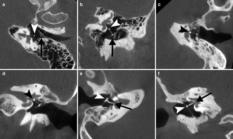
Fig. 5
Stapes prosthesis. a Photograph shows a Teflon type polymer stapes prosthesis. b Coronal CBCT image of the right ear demonstrates the Teflon prosthesis located underneath the tympanic segment of the facial canal and in contact with it (arrowhead) and with its tip on the stapes footplate (arrow). This correct position is confirmed on the double-oblique reformatted CBCT image (arrow). Not the hook of the prosthesis around the long apophysis of the incus
Fig. 6
Incus interposition a Diagram shows a surgically altered incus that has been placed between the malleus and stapes in an attempt to maintain ossicular function. (From Mukherji et al. 1994. With permission) b Photograph shows an example of a sculptured autologous incus interposition graft. The notch (arrow) will fit under the handle of the malleus and the circular groove (arrowhead) will be placed on the head of the stapes. Incus interposition homograft. c Axial CBCT image of the right ear shows a remodelled incus in contact with the tympanic membrane and malleus manubrium (arrowhead) and the stapes capitulum (arrow). d Double-oblique reformatted and coronal e CBCT image of the right ear in another patient show a remodelled incus (arrow) dislocated from the stapes capitulum (arrowhead), causing the conductive hearing loss
Fig. 7
Partial a, b and total c–f ossicular prostheses. a Para-axial double oblique and para-coronal b CBCT reformatted image of the left ear shows a normally positioned partial ossicular prosthesis with base (arrow) on a piece of cartilage placed on the tympanic membrane and tip on the stapes capitulum (arrowhead). c Para-axial double oblique and para-coronal d CBCT reformatted image of the left ear shows a total ossicular prosthesis with tip located on the stapes footplate (arrowhead). e Para-axial double oblique and para-coronal f CBCT reformatted image of the right ear shows a total ossicular allograft prosthesis with base on the tympanic membrane and malleus manubrium (arrowhead) and tip on the footplate (arrow)
Otological evaluation of patients who have undergone ossicular reconstruction is often difficult. CT can be helpful in demonstrating prosthetic failure (recurrent cholesteatoma, granulation tissue, adhesions or mechanical problems) that may cause post-operative CHL and identify patients in whom revision surgery must be considered (Stone et al. 2000).
2.3 Failure/Recurrence
2.3.1 Conventional Imaging Techniques
Clinical follow-up in CWD procedures is easy. In CWU, however, clinical and otoscopic diagnosis of residual (and recurrent) disease is unreliable, so second-look procedure is considered as an integral part of the CWU procedure by many authors. Imaging has an important role in the management of the post-operative middle ear (Williams and Ayache 2004). To avoid systematic second-look surgery and to better select the true surgical indications after CWU, imaging protocols have been developed with increasing accuracy, safety, and reliability. The primary goal of imaging in the management of postoperative cholesteatoma is to detect any residual or recurrent disease. Whatever imaging technique that is used to do so, if it wants to replace second-look surgery, it should be able to correctly differentiate granulation tissue, fibrosis, inflammatory tissue, fluid, from eventually residual cholesteatoma (Khemani et al. 2011). Until recently, no ideal imaging technique proved to be efficient enough to adequately confirm or eliminate a residual or recurrent cholesteatoma (Plouin-Gouan et al. 2010a).
CT has low sensitivity and low specificity, not allowing to differentiate between the different postoperative tissues such as recurrence, scar tissue or inflammation (Blaney et al. 2000). Therefore, it is now widely accepted that in the follow-up of patients after CWU mastoidectomy or bone obliteration technique (BOT), CT is useful only when it shows complete absence of a soft mass tissue within the post-operative cavity, or the evidence of a cholesteatomatous lesion filling the cavity, i.e. a nodular or lobulated enlarging soft tissue mass associated with osteolytic foci of the bony walls of the tympanomastoid cavity, or with ossicular displacement or destruction (Williams et al. 2003). In the vast majority of cases, however, a partially soft tissue opacification of the middle ear and mastoidectomy cavity is observed, and CT is not able to differentiate cholesteatoma from inflammation, scar tissue, granulation tissue or cholesterol granuloma (Tierney et al. 1999; Blaney et al. 2000) (Fig. 8). Therefore, MRI has become the imaging technique of choice.
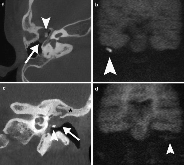
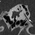
Fig. 8
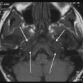
Value of CT imaging in the post-operative evaluation of cholesteatoma. a Axial CBCT image of the right ear show a status post CWU mastoidectomy and a soft tissue mass in the middle ear with convex borders (arrow). There is a medial displacement of the ossicles and subtle erosion of the malleus head (arrowhead). These features are highly suspicious of cholesteatoma which is confirmed by the high signal intensity (arrowhead) on the non-EPI DWI image b and by surgery. c Coronal CBCT image of a post-operative left ear with bony obliteration technique (asterisk) shows convex borders of a non-specific soft tissue mass (arrow) in the middle ear cavity. There is a remodelled incus (arrowhead) on the tympanic membrane. d The coronal non-EPI MR image shows isointense material consistent with granulation tissue (arrowhead). No cholesteatoma can be demonstrated
Conventional MR imaging in the post-operative evaluation for cholesteatoma consists of T1, T2 and Gd-enhanced T1-weighted images, where cholesteatoma is most often hyperintense on T2-weighted images, hypointense on T1-weighted images and does not enhance on postcontrast images, whereas chronic inflammation will show contrast enhancement. A typical rim enhancement may be seen around the cholesteatoma (Mark and Casselman 2002). It has been proven that also conventional MR imaging is not a valid alternative to second-look surgery in the case of cholesteatoma treated by CWU tympanoplasty (Van den Abeele et al. 1999).
The introduction of new imaging protocols including delayed contrast-enhanced MR imaging and especially the use of non-EPI DWI has totally changed the imaging strategy in the follow-up of patients after CWU mastoidectomy and BOT for cholesteatoma (Figs. 9 and 10) (De Foer et al. 2010).
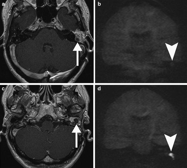
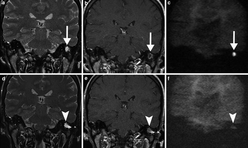
Fig. 9
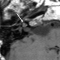
Post-operative MRI of a patient surgically treated for cholesteatoma. The exclusion cavity was filled up with fat. a Axial postcontrast T1-weighted MR image shows a hypointense nodular area (arrow) within the surrounding fat tissue which does not show restricted diffusion on the coronal non-EPI DWI image (arrowhead in b) consistent with granulation tissue. c Axial postcontrast T1-weighted MR image in the same patient more caudally demonstrates another nodular area (arrow) extending in the external auditory canal which is more hypointense than the area in a. d Coronal non-EPI DWI MR image confirms a recurrent cholesteatoma (arrowhead)
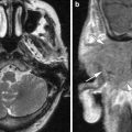
Fig. 10
Pre-operative a–c and post-operative d–f MRI of a patient with cholesteatoma 1 year after surgery. a Coronal T2-weighted MR image shows a homogeneous, sharply delineated mass in the mastoid (arrow). b On the coronal postcontrast T1-weighted MR image, the lesion has a non-enhancing centre with an enhancing rim (arrow) suspicious for cholesteatoma, which is confirmed on the coronal non-EPI DWI MR image (arrow in c). d Post-operative coronal T2-weighted MR image in the same patient again shows a homogeneous, sharply delineated mass in the same region of the previously located cholesteatoma (arrowhead). e The coronal postcontrast T1-weighted MR image shows that the centre of the lesion is more intense than pre-operatively (arrowhead) and does not show a high signal on the coronal non-EPI DWI MR image (arrowhead in f), which is compatible which protein-rich fluid or granulation tissue
2.3.2 Delayed Contrast-Enhanced MR Imaging
The initial results of delayed contrast-enhanced MR imaging in the detection of residual cholesteatoma were published in 2003 (Williams et al. 2003) and later confirmed in a larger series of patients by the same group (Ayache et al. 2005). A typical imaging delay after the intravenous injection of gadolinium of some 30–45 minutes is advocated. The protocol is based on the different vascularisation characteristics of cholesteatoma and other post-operative tissues: cholesteatoma is strictly avascular and scar tissue is poorly vascularised (possibly due to microvascular thrombosis). On delayed contrast-enhanced images, enhancement is typical centripetal; it eventually reaches the centre of the scar tissue mass 30–45 min after the contrast medium administration (Williams et al. 2003). With the use of delayed contrast-enhanced MRI residual cholesteatoma as small as 3 mm could be detected. Smaller pearls were probably missed due to signal averaging when a small cholesteatoma pearl is surrounded by granulation tissue (Williams et al. 2003). One could argument that there is probably no important risk to leave such a small residual cholesteatoma pearl for a few months if a close clinical and imaging follow-up is performed. It can be expected that this lesion will be detected on follow-up MRI performed 9–12 months later (Ayache et al. 2005). Although delayed contrast-enhanced MR imaging performs better than HRCT and conventional MR imaging, the sensitivity and specificity are relatively poor (Khemani et al. 2012). Moreover, drawbacks of this technique are poor spatial resolution (when compared to CT), long duration of the imaging protocol and need for intravenous injection of contrast media which make it more expensive and less practical to be used in children (Plouin-Gouan et al. 2010a).
2.3.3 Diffusion-Weighted MR Imaging
At the same time, the potential role of DWI in differentiating cholesteatoma from granulation tissue was suggested in a case report (Maheshwari and Mukherji 2002). The first series reporting on the high signal on DWI in primary cholesteatomas (Fitzek et al. 2002) and residual or recurrent cholesteatomas (Aikele et al. 2003) followed soon. Cholesteatoma is characterised by a high signal intensity on EPI and non-EPI DWI images with high b-values. The high signal intensity of cholesteatoma on the b-1000 diffusion images allows them to be differentiated from other lesions like fluid, inflammatory tissue, cholesterol granuloma, … which all have a low signal intensity (Figs. 9 and 10). The exact cause of this high signal intensity on DWI is still not completely understood. One explanation could be the decreased mobility of the water molecules in the residual cholesteatoma, so-called diffusion restriction. Another explanation for the increased intensity could be the T2-shine-through effect (Khemani et al. 2012).
Two different diffusion-weighting techniques are in use for detection of post-operative cholesteatoma: traditional spin-echo echo planar (EPI) and non-echo-planar (non-EPI) DWI.
EPI DWI is a very fast pulse sequence that can usually be performed in less than 1-2 minutes. EPI DWI fails to detect small cholesteatomas under 5 mm (Vercruysse et al. 2006). This may be explained by several reasons, among them susceptibility artefacts at the bone–air interface of the tegmen tympani, a low imaging matrix with relatively thick sections. Another limitation of the EPI DWI technique in demonstrating small cholesteatoma pearls are motion artefacts, which are responsible for smearing the hyperintense signal over different voxels (Stasolla et al. 2004). An overall sensitivity and specificity for detecting residual or recurrent cholesteatoma of 13–86 and 73–100 % has been described.
The large variation in sensitivity and specificity may be explained by differences in patient population and patient selection between various studies (i.e. patient selection based on CT findings or not, residual versus recurrent cholesteatoma). Stasolla et al. and Aikele et al. included in their series residual and recurrent cholesteatoma (Aikele et al. 2003; Stasolla et al. 2004), whereas Vercruysse et al. and Venail et al. selected patients with residual cholesteatoma only (Vercruysse et al. 2006; Venail et al. 2008). Incorporating both residual and recurrent cholesteatoma will result in a higher number of cholesteatoma of a larger size which may explain the higher sensitivities in these studies. Including only residual cholesteatoma on the other hand will result in a high number of smaller lesions, typically less than 5 mm, which explains the lower sensitivity in these studies (De Foer et al. 2011). Another explanation for the differences observed between studies could be the delay between MR imaging and surgery (Venail et al. 2008). Nevertheless, EPI DWI had higher specificity when compared to delayed contrast-enhanced MRI, despite its lower specificity (Venail et al. 2008). Several authors advocated therefore concurrent use of both these techniques for best diagnostic performance (Vercruysse et al. 2006; Venail et al. 2008; Lemmerling et al. 2008).
Technical improvements in sequence design have shifted from using EPI DWI sequences towards the use of non-EPI DWI sequences. Non-EPI techniques are less vulnerable to susceptibility artefacts and have higher spatial resolution due to the use of thinner slices and an increased imaging matrix, yielding sensitivities in the 90–100 % range for lesions as small as 2 mm (De Foer et al. 2008; Pizzini et al. 2010; Más-Estellés et al. 2012). Also, the estimated size correlated well with the operative findings, with all measurements having a discrepancy of no greater than 1 mm (Dheppnorrarat et al. 2009). On a technical note, De Foer et al. were the first to describe the use of a non-EPI single-shot turbo spin-echo (TSE) DWI sequence, i.e. a half-Fourier acquisition single-shot TSE (HASTE, Siemens Medical Systems, Erlangen, Germany) (De Foer et al. 2006). HASTE DWI is now the most reported non-EPI DWI sequence in detecting cholesteatoma (Jindal et al. 2011; Li et al. 2012). HASTE DWI allows the use of thinner sections (down to 2 mm slice thickness), a higher imaging matrix, with a complete lack of susceptibility artefacts (Dheppnorrarat et al. 2009). The non-EPI sequence from Philips is a multishot FSE DWI sequence (Philips Medical Systems, Best, The Netherlands, Dubrulle et al. 2006). PROPELLER DWI (Periodically Rotated Overlapping Parallel Lines with Enhanced Reconstruction) is the multishot non-EPI DWI sequence developed by General Electric (GE Healthcare, Milwaukee, WI, USA). The value of PROPELLER DWI in cholesteatoma was first evaluated on 3T (Lehmann et al. 2009) and more recently on 1.5T (Kasbekar et al. 2010; Más-Estellés et al. 2012). BLADE DWI (Siemens Medical Systems, Erlangen, Germany) is a similar multishot technique, based on a PROPELLER k-space trajectory. Multishot techniques are potentially susceptible to motion artefacts as multiple echoes contribute to a single diffusion measurement. To solve this problem, k-space is acquired through several radially orientated ‘propellers’ or ‘blades’. As the blades overlap at the centre of the k-space, there is relative oversampling resulting in an image with higher signal intensity and with reduced motion artefacts. Relative drawbacks of these techniques is that acquisition time is longer than with HASTE DWI and that the images can only be acquired in the axial plane, potentially resulting in poor visualisation of the tegmen tympani, which can be better evaluated on coronal images (Khemani et al. 2012). BLADE DWI has increased spatial resolution compared with the HASTE DWI technique (Schwartz et al. 2011). Both sequences may be included in post-operative cholesteatoma protocols. Because of its superior signal-to-noise ratio, the HASTE DWI sequence is often preferred since small recurrent cholesteatomas are sometimes more difficult to depict on BLADE DWI and better seen on HASTE DWI (Lane 2012).
HASTE DWI and PROPELLOR DWI have both been shown to have a higher diagnostic performance than delayed contrast-enhanced MR imaging in detecting cholesteatoma prior to second-look surgery (De Foer et al. 2010; Lehmann et al. 2009). Moreover, De Foer et al. compared delayed contrast-enhanced MR imaging with the HASTE DWI—alone and in combination—in the evaluation of cholesteatoma patients. They concluded that the HASTE DWI sequence can be used as a stand-alone screening sequence in cholesteatoma patients and that gadolinium administration is no longer required (De Foer et al. 2010). Similar findings have been reported by other groups (Dheppnorrarat et al. 2009; Huins et al. 2010; Pluoin-Gouan et al. 2010a; Rajan et al. 2010) and the routine use of non-EPI DWI for cholesteatoma screening is fast becoming a widely accepted practice within the radiological community. Many institutions have changed their imaging protocols, where delayed gadolinium-enhanced T1-weighted sequences are no longer used and axial and coronal T2-weighted sequences are added for orientation purposes. Plouin-Gouan et al. investigated the use of fusion of the DWI and HRCT images for more precise localisation of cholesteatomas (Pluoin-Gouan et al. 2010b). These new imaging protocols result in a substantial shortening of imaging time, cost saving for the healthcare system and a higher patient throughput for MR imaging (De Foer et al. 2010). As scanning time is very short (within 2 minutes), sedation or general anesthesia is usually not required in children (Rajan et al. 2010). Many institutions therefore now use non-EPI DWI for screening after CWU surgery and limit second-look surgery to patients with positive DWI (Khemani et al. 2012). Since cholesteatoma pearls less than 3 mm may be missed, further follow-up by MR imaging should be performed annually for 5 years (Geoffray et al. 2012). In our institutions, MRI follow-up is provided after 1, 3 and 5 years.
In a recently published meta-analysis of 342 patients, Li et al. concluded that non-EPI DWI may help to stratify patients into groups of who would benefit from early second-look surgery and who could be closely observed (Li et al. 2012). The overall pooled sensitivity was 94 % and specificity was 94 %. A total of 30 false negatives and 8 false positives were described. The majority of false negative results were due to cholesteatoma pearls measuring less than 3 mm in size, thus exceeding the lower limit of reliability of current imaging technology. Apart from cholesteatoma size, false-negative cases were also attributed to auto-evacuating retraction pockets (aka mural cholesteatomas) and image degradation from motion artefacts. In these cases of empty cholesteatoma pockets—either by auto-evacuation or by suction cleaning—no typical solid ‘onionlike mass’ filled with keratin debris was present at the moment of revision surgery. Instead, these lesions had the appearance of a deep retraction pocket, with a macroscopically epithelial lining but lacking the presence of firm keratin. Since DWI detects the keratin content of a cholesteatoma, it is unlikely to detect these recurrent retraction pockets without keratin or residual matrix (Dheppnorrarat et al. 2009; Rajan et al. 2010; De Foer et al. 2011; Jeunen et al. 2008). Another false-negative case was a DWI hypointense lesion, hypointense in T2 and hyperintense in T1 without postcontrast enhancing that was interpreted as a subacute or recurrent bleeding in the tissue (Profant et al. 2012).
False positive findings with hyperintensities not corresponding to a cholesteatoma have been described in various situations: after recent surgery (residual haemorrhage), in ears containing silastic sheets and prosthesis (Venail et al. 2008; Geoffray et al. 2012), bone powder (Dubrulle et al. 2006) or a fat plug (Dremmen et al. 2012), scar tissue (Venail et al. 2008; Jeunen et al. 2008), cerumen in the EAC (Kasbekar et al. 2010), cholesterol granuloma (Kösling and Bootz 2001), middle ear or mastoid abscesses (Dremmen et al. 2012; Profant et al. 2012), endocrine adenoma (Barath et al. 2011) and artefacts due to metallic dental braces (Pluoin-Gouan et al. 2010a; Más-Estellés et al. 2012). When non-EPI DWI sequences are not available, susceptibility artefacts on EPI DWI may be a cause for false positive findings (Cimsit et al. 2010).
Clinical and otoscopic findings as well as details from the surgical intervention may help to avoid these pitfalls. In most cases, conventional MRI-sequences (T1, T2, Gd-T1) will be able to differentiate fat plugs and cholesterol granuloma from cholesteatoma (Dremmen et al. 2012). When in doubt, ADC values can be measured; ADC values are usually much higher in cholesterol granuloma than in cholesteatomas. Also, to discriminate abscesses from cholesteatomas, ADC measurements may be helpful; lesions containing pus show very low ADC values (<0.5 × 10⁻³ mm2/s). These values have been reported to be higher in cholesteatomas and intermediate when cholesteatoma and infection coexist (Thiriat et al. 2009; Lingam et al. 2013). When DWI suggests recurrence, some institutions add delayed contrast-enhanced imaging to confirm the recurrence and only these children undergo surgery (Geoffray et al. 2012).
Although MR imaging at 3T is becoming more common and available, data on the value and/or benefits of 3T over 1.5T in imaging the petrous bone are scarce and mostly related to imaging of diseases involving the inner ear, such as Menière’s disease (Naganawa and Nakashima 2009). Theoretical advantages of 3T over 1.5T are increased signal-to-noise ratio, faster imaging which is less sensitive to patient motion (e.g. in children), and increased spatial and contrast resolution. Disadvantages are increase in RF deposition (SAR) and increased susceptibility artefacts (Schmitz et al. 2005). To the best of our knowledge only two papers have been published using 3T in the evaluation of middle ear cholesteatoma. Similar results comparing EPI DWI and non-EPI PROPELLER DWI on 3T were observed (Lehmann et al. 2009). The resolution power of HASTE on 3T was 2 mm (Pizzini et al. 2010), which is the same as on 1.5T.
3 Stapes Surgery in Otosclerosis Patients
Many diseases and dysplasias can affect the osseous components of the temporal bone. Some diseases such as otosclerosis are limited to the temporal bone and do not occur elsewhere in the body (Hasso et al. 1996). The term ‘otosclerosis’ was introduced by Adam Politzer, who described the histopathological findings in 1894 (Declau et al. 2001). Otosclerosis occurs in two phases: an early, active phase, during which bone resorption occurs (otospongiotic stage) and a later, inactive phase (sclerotic stage). Diagnosis of otosclerosis is based on clinical findings, audiometric testing and family history, but medical imaging is often demanded to confirm the diagnosis (Nowé et al. 2004). The typical clinical features of otosclerosis are gradually increasing hearing loss (HL), most frequently occurring between the third and fifth decades. Although usually both ears are affected, often there is an asymmetry in HL with one ear showing a greater conductive impairment. Tinnitus is a common symptom and it may become louder as the HL progresses. The origin of the tinnitus is not clear but it may be the result of cochlear degeneration or an abnormal degree of vascularity within the labyrinthine capsule. Vertigo is rare and is probably the effect of toxic enzymes on the vestibular labyrinth (de Bruijn 2000). In otosclerosis, three major patterns of involvement are discerned: fenestral, retrofenestral and mixed. First, a purely fenestral type, which involves the oval window, most commonly the anterior aspect in the approximate location of the embryologic fissula ante fenestram. The second type is a retrofenestral (cochlear) form, primarily involving the cochlea, with SNHL as a result. Both types of otosclerosis may coexist in one patient, resulting in mixed hearing loss (d’Archambeau et al. 1990).
Related posts:

Stay updated, free articles. Join our Telegram channel

Full access? Get Clinical Tree


