Pseudo lesions
Vascular anatomical variants
Tumors with rich vascularity
Acquired vascular lesions
Vascularized chronic inflammation tissue
Vascular malformations
Vascular anatomical variants frequently are not associated with symptoms.
2 Imaging Strategy in PT
The pre-imaging evaluation of a patient consists of a detailed history, looking for hearing loss, vertigo, headaches, and a medical examination including a neuro-otologic and audiologic evaluation.
There is a wide variation in the reported incidence of structural abnormalities in patients with PT ranging from 44 to 91 % (Madani and Connors 2009). Diagnostic imaging, even performed optimally, fails to find a reason for PT in many patients (Verbist et al. 2011). If an intratympanic mass is seen at otoscopy, then the imaging analysis can start with a CT, thin sections with bone algorithm in the axial and coronal plane, of the temporal bone and adjacent structures of the skull base. The anatomy of the carotid canal and the jugular foramen is carefully studied. For the anatomical vascular variants and small soft tissue masses, like a small glomus tympanicum no further study is needed. For larger masses, an MRI examination is complementary and the CT study can be done without intravenous contrast. Various imaging strategies have been proposed for the investigation of PT in the otoscopically normal patient. Combined CT angiography (CTA) and CT venography (CTV) with a multidetector CT is a good approach for demonstrating arterial, venous, skull base and middle ear disease. MR and MR angiography cannot be trusted to confidently exclude all causes (Krishnan et al. 2006; Mattox and Hudgins 2008; Narvid et al. 2011; Verbist et al. 2011) (Table 2). Our protocol for the imaging analysis op PT consists of an CTA & CTV. The lower scan border is the level of vertebra cervical 7 and the upper border is the end of the skull. The lower border is chosen to include the carotid bifurcation in the protocol. The upper border is chosen for the detection of a possible high flow intracranial AVM, whereby the venous drainage is causing PT. Post-processing includes maximum intensity projections in the axial, coronal and sagittal planes. There are also separate multiplanar bony algorithm reconstructions of the right and left temporal bone with thin slices of 0.75 mm in the axial and coronal plane to detect an anatomical vascular variant or another intratemporal cause of the PT. For the detection of a dural arteriovenous fistula (DAVF) you have to look to: asymmetric arterial feeding vessels, “shaggy” appearance of a dural venous sinus, transcalvarial venous channels, asymmetric venous collaterals and abnormal size and number of cortical veins. The presence of asymmetrically visible and enlarged arterial feeders has a high sensitivity and specificity for the diagnosis of a DAVF (Fig. 1). A conventional digital subtraction angiography (DSA) is necessary in cases of a negative CTA, but a strong clinical suspicion and in the presence of vascular malformations to demonstrate the angioarchitecture and in case of endovascular treatment (Narvid et al. 2011).
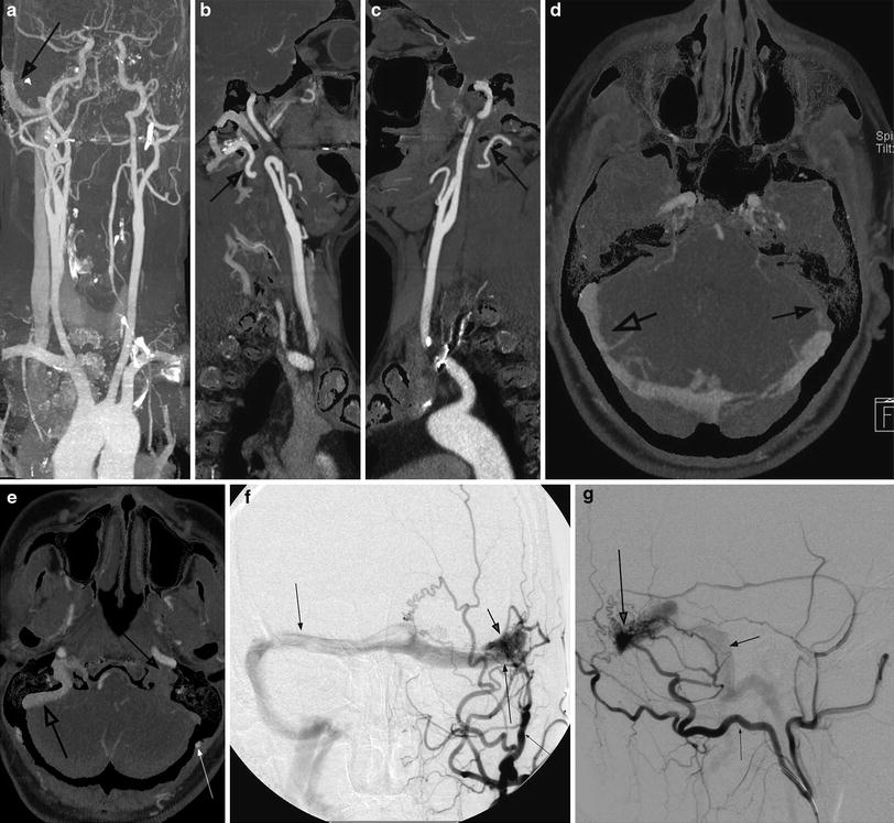
Table 2
Imaging strategy in pulsatile tinnitus
Otoscopy: intratympanic mass | Small lesion | Only CT |
Vascular variants | Only CT | |
Large lesion | CT and MRI | |
Otoscopy: no intratympanic mass | CTA and CTV |
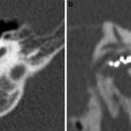
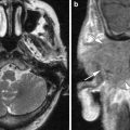
Fig. 1
Use of CTA: dural A-V fistula left with contralateral right venous drainage. CT Siemens Flash Definition double source/double energy with use of CT-angiography subtraction. a CTA- subtraction. Early venous drainage in right transverse, sigmoid sinus (arrow). b Left common carotid artery shows hypertrophy of the occipital artery (arrow). c Right common carotid artery with a normal occipital artery (arrow). d–e Axial reconstruction shows in the arterial phase early venous drainage left (large arrow), no contrast in left sigmoid sinus (middle-sized arrow) en hypertrophy of left occipital artery (small arrow). f–g DSA confirms the dural A-V fistula with nidus in the left transverse sinus (large arrow), the occlusion of the left sigmoid sinus (middle-sized arrow), the contralateral venous drainage (middle-sized arrow) and the feeding vessels, most important the hypertrophied occipital artery (small arrow)
3 Vascular Anatomical Variants
Vascular anatomical variants of the temporal bone are a frequent cause of PT or a vascular retrotympanic mass that often clinically cannot be differentiated from a paraganglioma. This differentiation is important prior to biopsy or therapy. Often these variants are an incidental asymptomatic finding on a CT done for other reasons (Table 3). The radiological diagnosis is possible with MRI, MR angiography, and with CT. For some variants, like the dehiscent jugular bulb, the bone detail, available with CT is important. On MR spin echo sequences, the signal void of the abnormally located artery or vein may be identical to the signal void of the cortical bone and the air in the ear and the anomaly can be missed. A gradient echo sequence gives a high signal from the vessel with better differentiation from the cortical bone.
Table 3
Vascular anatomical variants
Arterial | Venous |
The aberrant ICA | High jugular bulb |
Hyostapedial artery variants | Dehiscent jugular bulb |
Laterally displaced ICA | Jugular bulb diverticulum |
Isolated agenesis of the ICA | |
Pharyngo-tympano-stapedial artery | |
Splitting of the petrous ICA |
3.1 Arterial Variants
3.1.1 The Aberrant Internal Carotid Artery
The aberrant internal carotid artery (ICA) also called the aberrant flow of the internal carotid artery in the tympanic cavity (Lasjaunias et al. 2001) enters the skull base through an enlarged inferior tympanic canaliculus with a characteristic narrowing of the vessel. The fundamental cause is a segmental agenesis, absence of the cervical part of the internal carotid artery with the subsequent absence of the vertical part of the bony carotid canal. The ascending pharyngeal artery with its tympanic branch (going through its own enlarged inferior tympanic canaliculus) serves as a collateral pathway to the normal horizontal part of the ICA. At the end of the inferior tympanic canaliculus, the artery enters the middle ear cavity and is located behind the tympanic membrane at the promontorium as a “vascular mass,” not covered by bone, before entering the horizontal part of the carotid canal through a bony dehiscence. An aberrant ICA can be associated with a persistent stapedial artery (vide infra; Tanghe 1994; Weisman and Hirsch 2000).
This anomaly can present with objective or subjective pulsatile tinnitus and conductive hearing loss. On otoscopy the ENT surgeon finds a vascular appearing retrotympanic mass that mimics a paraganglioma. A misdiagnosis as a glomus tympanicum must be avoided: the operation can result in a debacle (Tanghe 1994).
The CT features are characteristic (Table 4): (1) absence of a normal-appearing vertical segment of the carotid canal; (2) absence of the bony wall in the posterolateral portion of the horizontal segment of the carotid canal; (3) a round soft tissue mass in the middle ear at the promontorium. Especially in a coronal section this mass can look similar to a glomus tympanicum; (4) on axial CT this mass is in continuity with the horizontal segment of the carotid canal; (5) the aberrant ICA enters the tympanic cavity through an enlarged inferior tympanic canaliculus, located more lateral and posterior compared to a normal vertical ICA segment (Tanghe 1994) (Fig. 2). On conventional MRI, the diagnosis of an aberrant ICA is difficult because of the lack of contrast between the low signal of bone, the signal void of the ICA, and the air in the middle ear and mastoid portion. Flow-sensitive MR images or MR angiography (MRA) allow the diagnosis. Conventional angiography is not necessary for the diagnosis (Weisman and Hirsch 2000).
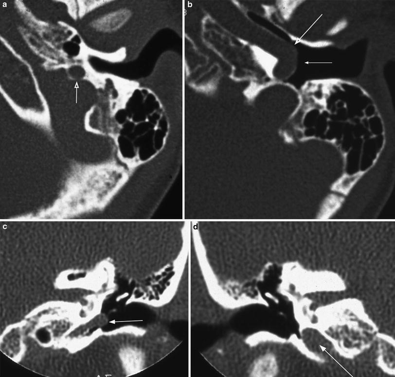
Table 4
CT appearance of the “aberrant ICA”
1 | Absence of the vertical part of the carotid canal |
2 | Enlarged inferior tympanic canaliculus |
3 | The vertical segment of the ICA enters the temporal bone through (2), running more posterior and laterally than normal |
4 | Absence of the normal bony posterior margin of the horizontal part of the carotid canal |
5 | Soft tissue density in the middle ear at the level of the promontory, joining the horizontal carotid canal through the bony defect mentioned in (4) and simulating a paraganglioma |
6 | “Stenosis” at the entry point in the horizontal carotid canal |
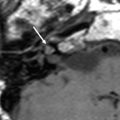
Fig. 2
Aberrant internal carotid artery. a Axial CT at the level of the enlarged inferior tympanic canaliculus. This canal is located more lateral and is smaller than the normal vertical part of the carotid canal (arrow). b Axial CT at the level of the horizontal part of the carotid canal. Part of the lateral bony wall is absent (large arrow) and the carotid artery comes close to the tympanic membrane (small arrow). c Coronal CT at the level of the genu in a different patient. The carotid artery reaches the tympanic membrane (arrow). The inferior tympanic canaliculus is smaller than the normal vertical part of the carotid canal at the opposite site in d (arrow)
3.1.2 Partial Persistence of the Stapedial Artery
The so-called “persistent stapedial artery” is in fact a partial persistence of the stapedial artery, different from the full persistent variant which is vary rare (Lasjaunias et al. 2001). The partial persistent variant is an intratympanic origin of the middle meningeal artery. The artery originates from the ICA between the vertical and the horizontal portion of the carotid canal. It enters the middle ear cavity anteroinferiorly, runs along the promontory, passes between the crura of the stapes and enters the tympanic segment of the facial canal causing an enlargement of this canal. At the level of the first genu, it leaves the facial canal through its own foramen and enters the extradural space of the middle cranial fossa, becoming the middle meningeal artery (MMA) (Tanghe 1994). It can be associated with an aberrant ICA (Fig. 3) and with an aneurysmal enlarged ICA (Fig. 4).
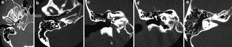
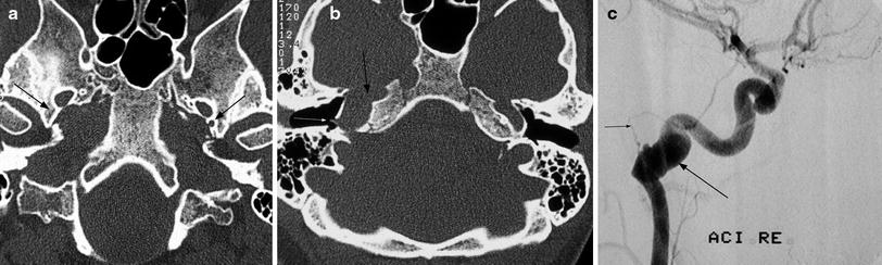
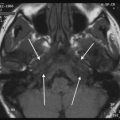
Fig. 3
Persistent stapedial artery, associated with an aberrant internal carotid artery. a Axial CT. The foramen spinosum is absent (large arrow), compared with the normal left side. The carotid artery is in contact with the tympanic membrane through a bony defect at the end of inferior tympanic canaliculus (small arrow). There is no bony margin between the inferior tympanic canaliculus and the jugular foramen. b Axial CT. The carotid artery lies in the middle ear with a large bony defect in the horizontal part of the carotid canal (large arrow). Notice the origin of the persistent stapedial artery (small arrow). c Coronal CT at the level of the oval window; d, e coronal and axial CT at the level of the proximal tympanic segment of the facial canal. The facial canal at the level of the oval window is still normal in size (small arrow), but it is enlarged at his proximal tympanic segment, to accommodate for the persistent stapedial artery (large arrow). The labyrinthine segment of the facial canal is normal (small arrow in e)
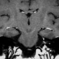
Fig. 4
Persistent stapedial artery, associated with aneurysmal enlargement of the carotid artery. a Axial CT of the skull base. The foramen spinosum is absent on the right side (arrow) and normal on the left side (arrow). b Axial CT at the level of the horizontal part of the carotid canal. The canal is enlarged (large arrow). Also notice the origin of the persistent stapedial artery (small arrow). c The angiogram in the same patient shows the fusiform aneurysmal enlargement of the carotid artery (large arrow) and the persistent stapedial artery (small arrow)
This vascular variant is most often an incidental finding at operation or on a CT examination (easily overlooked) and rarely symptomatic with pulsatile tinnitus.
A persistent stapedial artery cannot be diagnosed with MR or even MRA. The CT features are pathognomonic (Tanghe 1994) (Table 5): (1) absence of the foramen spinosum, because there is no MMA to go through; (2) erosion of the promontory; (3) widening of the proximal tympanic segment of the facial canal to accommodate for the artery; and (4) absence of the MMA from the internal maxillary artery on angiography.
Table 5


CT appearance of the partial persistent stapedial artery
Related posts:

Stay updated, free articles. Join our Telegram channel
Full access? Get Clinical Tree
