chapter 14 The Gamma Camera
Performance Characteristics
The performance of a gamma camera system is defined by the sharpness and detail of the images it produces, the efficiency with which it detects incident radiation, its ability to measure the energy of the incident γ rays (to minimize scatter), and the counting rate it can handle without significant dead time losses. A gamma camera is not capable of producing “perfect” images of the radionuclide distribution. Certain inherent imperfections arise from the performance characteristics of the detector, its associated electronic circuitry, and the collimator. Image artifacts also can be caused by malfunctions of various camera components. In this chapter, we describe the major factors that determine gamma camera performance and examine the limitations that can lead to artifacts in gamma camera images and their correction. Standard tests of gamma camera performance also are summarized.
A Basic Performance Characteristics
1 Intrinsic Spatial Resolution
Intrinsic resolution is limited primarily by two factors. The first is multiple scattering of γ-ray photons within the detector. If a photon undergoes Compton scattering within the detector crystal and the residual scattered photon also is detected, but at some distance away, the two events are recorded as a single event occurring at a location along the line joining the two interaction sites. This is not a serious cause of degraded resolution for photon energies  300 keV in which multiple scatter Compton interactions in NaI(Tl) are almost negligible. Even at 662 keV, Anger calculated that for a detector thickness of 6.4 mm, less than 10% of photons are misplaced by more than 2.5 mm as a result of multiple scattering events.1
The second, and primary, cause of limited intrinsic resolution is statistical fluctuation in the distribution of light photons among photomultiplier (PM) tubes from one scintillation event to the next. The problem is exactly analogous to the statistical fluctuations observed in radioactive decay, discussed in Chapter 9. If a certain PM tube records, on average, N light photons from scintillation events occurring at a certain location in the detector crystal, the actual number recorded from one event to the next varies with a standard deviation given by  . Thus if a very narrow beam of γ rays is directed at a point on the detector, the position of each event as determined by the positioning circuitry or computer algorithm is not precisely the same. Rather, they are distributed over a certain area, the size of which depends on the magnitude of these statistical fluctuations.
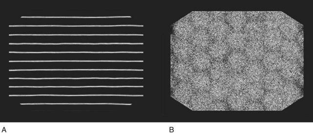
A detailed method for measuring and characterizing intrinsic spatial resolution is discussed in Section E.1. Typically, a lead mask containing a number of narrow (~1 mm) slits is placed on the face of the gamma camera (without the collimator) and the camera is irradiated using a 99mTc (140-keV) point source. The resulting image is a series of lines corresponding to the locations of the slits (e.g., see Fig. 14-10A). The resolution is calculated as the full width at half maximum (FWHM) of a profile drawn perpendicular to the image of the lines at various locations in the field of view. The intrinsic spatial resolution of modern large field-of-view gamma cameras measured with 99mTc in this manner is in the range of 2.9- to 4.5-mm FWHM. Because the resolution is considerably worse than the width of the slits, the contribution of the slits themselves to the measured resolution is very small ( 10% for measured resolution
  2.5 mm).
Intrinsic resolution becomes worse with decreasing γ-ray energy because lower-energy γ rays produce fewer light photons per scintillation event, and smaller numbers of light photons result in larger relative statistical fluctuations in their distribution (Chapter 9, Section B.1). As a rule of thumb, intrinsic resolution is proportional to  , in which E is the γ-ray energy. This follows because the number of scintillation light photons produced, N, is roughly proportional to E and the relative statistical fluctuations in their distribution are therefore proportional to
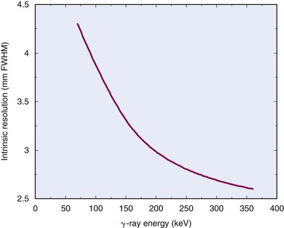
  . This causes noticeably greater blurring at lower γ-ray energies. An example of the change of intrinsic spatial resolution as a function of γ-ray energy is shown in Figure 14-1.
Intrinsic resolution also depends on detector crystal thickness. Thicker detectors result in greater spreading of scintillation light before it reaches the PM tubes. Furthermore, there is a greater likelihood of detecting multiple Compton-scattered events in thicker detectors, particularly with higher-energy radionuclides. These are the primary reasons why gamma cameras use relatively thin detectors in comparison with NaI(Tl) systems that are used for counting applications. Figure 14-2 shows an example of the intrinsic spatial resolution versus crystal thickness for 140-keV γ rays.
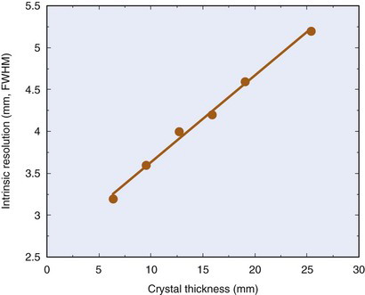
FIGURE 14-2 Intrinsic spatial resolution of a gamma camera at 140 keV as a function of crystal thickness.
(Compiled with data from Sano RM, Tinkel JB, LaVallee CA, Freedman GS: Consequences of crystal thickness reduction on gamma camera resolution and sensitivity. J Nucl Med 19:712-713, 1978; Muehllehner G: Effect of crystal thickness on scintillation camera performance. J Nucl Med 20:992-993, 1979; Royal HD, Brown PH, Claunch BC: Effects of reduction in crystal thickness on Anger camera performance. J Nucl Med 20:977-980, 1979; Chapman D, Newcomer K, Berman D, et al: Half-inch versus quarter-inch Anger camera technology: Resolution and sensitivity differences at low photo-peak energies. J Nucl Med 20:610-611, 1979; and unpublished data from Dr. Joel Karp, University of Pennsylvania, Philadelphia, PA.)
Intrinsic resolution improves with increased efficiency of collection of scintillation photons. Modern cameras are substantially improved over earlier versions in this regard because of the use of more efficient PM tubes and of better techniques for optical coupling between the detector crystal and the PM tubes. The use of greater numbers of smaller PM tubes (5-cm-diameter tubes have become the standard, and some gamma cameras have as many as 110 PM tubes per head) and improved electronics also have contributed to this improvement. Accurate corrections for nonlinearity (see Section B.1) and nonuniformity (see Section B.2) have also resulted directly in improvements in intrinsic resolution, as discussed in the following sections. The best reported intrinsic resolution for a large field-of-view gamma camera is just below 3 mm FWHM at 140 keV (99mTc). Significant improvements beyond approximately 2 mm FWHM will be difficult to achieve, owing to the ultimate limitation of the light photon yield of NaI(Tl). In most practical situations, however, the intrinsic spatial resolution makes a negligible contribution to the overall system resolution of the gamma camera, which is largely determined by the resolution of the collimator (see Sections C and D).
2 Detection Efficiency
The gamma camera employs a sodium iodide crystal that is relatively thin in comparison with most other sodium iodide detectors used in nuclear medicine: 6.4 to 12.7 mm versus 2 to 5 cm for probe counting systems, scanners, and so on. The trade-off in gamma cameras is between detection efficiency (which improves with thicker crystals) and intrinsic spatial resolution (which improves with thinner crystals—see Fig. 14-2). The gamma camera is designed to provide acceptable detection efficiency while maintaining high intrinsic spatial resolution in the energy range of 100-200 keV. As a result, the detection efficiency of the gamma camera detector is somewhat less than would be desirable at higher γ-ray energies.
Figure 14-3 shows photopeak detection efficiency versus γ-ray energy for the gamma camera detector for a range of NaI(Tl) crystal thicknesses. The gamma camera is nearly 100% efficient for energies up to approximately 100 keV for all crystal thicknesses, but then shows a rather marked decrease in efficiency at higher energies, depending on crystal thickness. At 140 keV (γ-ray energy of 99mTc), the difference in efficiency between 6.4-mm and 12.7-mm-thick crystals is approximately 20% and the photopeak detection efficiency is in the 70% to 90% range. At approximately 500 keV, the standard gamma camera (detectors 0.64-0.95-cm-thick) is less than 20% efficient at converting incident γ rays into photopeak pulses.
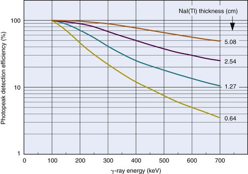
FIGURE 14-3 Photopeak detection efficiency versus γ-ray energy for NaI(Tl) detectors of different thicknesses.
(Adapted from Anger HO: Radioisotope cameras. In Hine GJ [ed]: Instrumentation in Nuclear Medicine, Vol 1. New York, 1967, Academic Press, p 506.)
At high energies, the performance of gamma cameras with 0.64- to 1.27-cm-thick crystals is limited by decreasing detection efficiency (as well as increasing collimator septal penetration—see Section C.2). Deteriorating intrinsic spatial resolution becomes the limiting factor at lower energies. Because of these tradeoffs, the optimal γ-ray energy range is approximately 100 to 200 keV for most gamma cameras. Some gamma cameras are now fitted with thicker crystals (12.7-25.4 mm), enabling them to achieve improved efficiency for imaging positron-emitting radionuclides at 511 keV (Chapter 18, Section B.4). This comes at the expense of some loss of intrinsic spatial resolution (see Fig. 14-2) when these systems are used in the 100-200-keV energy range.
3 Energy Resolution
It is not unusual in a typical patient study for there to be more Compton-scattered than unscattered γ rays striking the detector (see Fig. 11-9). Because the Compton-scattered photons have lower energy, it is possible to discriminate against them using pulse-height analysis. The energy resolution of the detector determines the efficiency with which this can be accomplished. Good energy resolution is perhaps the most important performance feature of the camera system for this purpose.
Energy resolution, like intrinsic spatial resolution, depends largely on statistical fluctuations in the number of light photons collected from a scintillation event (Chapter 10, Section B.7). Thus good light collection efficiency is a prerequisite for good energy resolution. As well, because the number of light photons released in a scintillation event increases almost linearly with γ-ray energy, E, (Fig. 10-11), energy resolution improves approximately in proportion to  (Fig. 10-13).
The energy resolution for gamma cameras is typically in the 9% to 11% range for 99mTc. Figure 14-4 shows a typical gamma camera spectrum for 99mTc with the pulse-height analyzer (PHA) window set to 130 to 150 keV. This corresponds to approximately a 15% energy window, which is a common setting for clinical studies. As illustrated by the figure, most of the events in the photopeak are accepted within this window. According to Equation 6-11, a low-energy threshold of 130 keV should reject 140-keV γ rays that have been scattered through angles greater than approximately 45 degrees. However, because the spectrum for scattered γ rays is blurred in the same way as the spectrum for unscattered ones, the rejection efficiency for this scattering angle is only approximately 50%; half of the events produce pulses above the threshold, and half below it. This percentage would apply for 45-degree scattered 140-keV γ rays and a 130-keV lower energy level, regardless of the energy resolution of the detector. Gamma rays scattered through greater angles are rejected more efficiently, and those scattered through smaller angles are rejected less efficiently.

Two advantages are obtained with improved energy resolution. First, the photopeak becomes narrower, resulting in more efficient detection of unscattered photons within the chosen energy window. This increases the number of valid events recorded and improves the statistical quality of the image. Second, γ rays scattered through large angles are rejected more efficiently, because their energy spread within the pulse-height spectrum is also smaller. Thus image contrast is improved. It also is true that γ rays scattered through smaller angles are detected somewhat more efficiently, because of the narrowing of their distribution as well. However, the increased efficiency for recording photopeak events more than offsets this effect, in terms of contrast-to-noise ratio (Chapter 15, Section D.2). Alternatively, one can take advantage of the improved energy resolution to use a narrower PHA window, trading back some of the increased efficiency for recording photopeak events for improved rejection of small-angle scatter. Either way, improved energy resolution results in better image quality.
4 Performance at High Counting Rates
At high counting rates, there is increased likelihood of recording two events at the same time. The most troublesome effect is known as pulse pile-up (Chapter 8, Section B.3). Pulse pile-up has two undesirable effects on gamma camera performance: counting losses and image distortion.
Counting losses cause inaccurate counting rates to be recorded at higher counting rates. The inaccuracies are described by conventional dead time models (Chapter 11, Section C) and may be significant in some high-count-rate quantitative studies, such as first-pass cardiac studies. Dead time corrections can be applied; however, these corrections generally become increasingly inaccurate as counting losses increase.
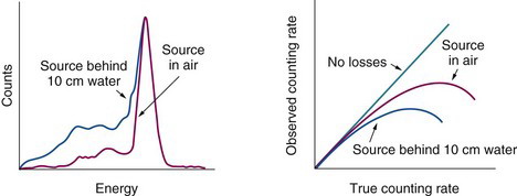
Because pulse pile-up can occur between any two events in the pulse-height spectrum, system counting losses are determined by total-spectrum counting rates. Most gamma cameras behave as paralyzable systems. The apparent dead time for a selected energy window depends on the window fraction, that is, the fraction of the total spectrum counting rate occurring within that window. The smaller the window fraction, the larger the apparent dead time. Thus the apparent dead time is longer when a photopeak window is used than when a full-spectrum window is used. The apparent dead time also is longer when scattered radiation is present, because this also adds to the counting rate outside the photopeak window (Fig. 14-5). Therefore, when specifying gamma camera dead time, it is important to note the conditions of measurement. Dead time values as short as 1 to 2 µsec can be obtained in the absence of scattering material with a full-spectrum window; however, under clinically realistic conditions (99mTc source in scattering material, 15% photopeak window), system dead times of 4 to 8 µsec are more typical. For a dead time of 5 µsec, counting losses are approximately 20% for a counting rate of 4 × 10⁴ counts per second (cps).
Dead time losses are not serious in most static imaging studies, but they can be important in certain high-counting-rate applications (e.g., first-pass cardiac studies) in which counting rates as high as 105 cps may occur. Pile-up rejection circuitry (see Chapter 8, Section B.3) is used to achieve higher usable counting rates in such situations. Another approach for shortening camera dead time is by the use of analog buffers, or derandomizers. These are electronic circuits that “hold” a voltage level or pulse from one circuit component (e.g., an amplifier) until the next circuit in the pulse-processing sequence (e.g., the PHA) is ready to receive it.
Similarly, in digital gamma cameras, data can be buffered in memory until the computer is ready to process them. Both these approaches result in a decrease in the “apparent” dead time of the camera by effectively changing the arrival times of the pulses. This, however, means that the simple dead time models and corrections presented in Chapter 11, Section C can no longer be used, and more complex modeling of system dead time must be carried out to produce accurate correction at high counting rates.
It also is possible to physically shorten the dead time of a camera by shortening the charge integration time from the PM tubes and using electronic circuitry that returns the signal to baseline after the chosen integration time.2 Clearly, this also decreases the amount of signal used for determining event location. For example, with a charge integration time of 0.4 µsec, only 81% of the scintillation light is collected, compared with 98% for a 1-µsec integration time. This causes a degradation of intrinsic spatial resolution and energy resolution. Some gamma cameras have a variable integration time, in which the charge integration is automatically shortened as the counting rate increases.
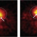
The second undesirable effect of pulse pile-up is image distortion. Using standard pulse-positioning logic for gamma cameras (see Chapter 13, Section B.2), two events detected simultaneously at different locations in the detector are recorded as a single event with energy equal to the sum of the two events, at a location somewhere between them (Fig. 14-6). If both are valid photopeak events, their total energy exceeds the value that would be accepted by the PHA window and both events are rejected, resulting in counting losses. On the other hand, it is possible for two Compton-scattered γ rays to have a total energy that falls within the selected energy window, so that two invalid events are accepted as a single valid event. The visible result at very high counting rates is to add a diffuse background to the image, as illustrated in Figure 14-7. Note as well the image in the upper right-hand corner of this figure, showing how contrast can be restored by shielding high-activity areas outside the imaging area of interest (e.g., with a thin sheet of lead).
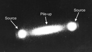
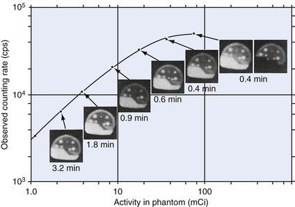
FIGURE 14-7 Demonstration of pile-up effects on images of a brain phantom. Times required to record 1.2 × 10⁶ counts are indicated. At very high counting rates there is a noticeable loss of image contrast, which can be restored by shielding useless high-activity areas from the detector (top right-hand image).
Many gamma cameras now incorporate circuits that continuously monitor the decay of a pulse and use a method based on pulse-tail extrapolation for pile-up correction. Consider two γ-ray interactions that occur close together in time and create overlapping pulses. When the second γ ray arrives, the decay of the pulse created by the first γ ray immediately deviates from the expected exponential decay and the gamma camera signal is switched to a second amplifier circuit. Estimator circuitry in the first amplifier circuit completes the signal from the first γ ray by extrapolating the remainder of the tail of the pulse with an exponential function based on the decay time of NaI(Tl). At the same time, this extrapolated tail is also sent to the second amplifier circuit and subtracted from the second pulse. This removes the contribution of the pulse generated by the first γ ray from that of the second γ ray. This process is summarized in Figure 14-8. The pulse-tail extrapolation technique results in both events being retained and allows them to contribute to the image, providing they also meet the PHA requirements. This method is very effective, unless the two pulses occur nearly simultaneously (within a few tens of nanoseconds of each other), in which case the extrapolation is of limited accuracy.
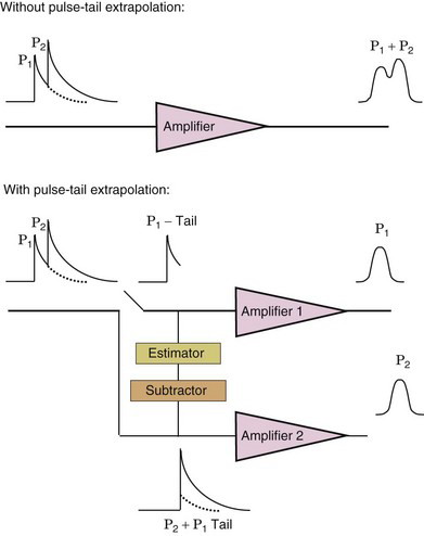
FIGURE 14-8 Illustration of pile-up correction using pulse-tail extrapolation techniques. See text for details.
(Adapted from Lewellen TK, Pollard KR, Bice AN, Zhu JB: A new clinical scintillation camera with pulse tail extrapolation electronics. IEEE Trans Nucl Sci 37:702-706, 1990.)
B Detector Limitations: Nonuniformity and Nonlinearity
1 Image Nonlinearity
A basic problem arising in the detector and electronics is image nonlinearity. Straight-line objects appear as curved-line images. An inward “bowing” of line images is called pincushion distortion; an outward bowing is called barrel distortion (Fig. 14-9). Nonlinearities result when the X- and Y-position signals do not change linearly with displacement distance of a radiation source across the face of the detector. For example, when a source is moved from the edge of one of the PM tubes toward its center, the light collection efficiency of that PM tube increases more rapidly than the distance the source is moved. This causes the image of a line source crossing in front of a PM tube to be bowed toward its center. The result is a characteristic pincushion distortion in areas of a gamma camera image lying directly in front of the PM tubes, and barrel distortion between them. Differences in sensitivity among the PM tubes, nonuniformities in optical light guides, as well as PM tube or electronic malfunctions, also can cause nonlinearities.

Figure 14-10A, shows an image of a straight-line “test pattern” recorded on a modern gamma camera to demonstrate the general appearance of nonlinearities. On close inspection, some waviness of the lines is apparent. On properly functioning cameras, including the one illustrated, the nonlinearities themselves (including the pincushion distortions in front of PM tubes) are barely perceptible and rarely interfere directly with image interpretation; however, they can have significant effects on image nonuniformities, as discussed in the following section.