Fig. 27.1
Aortic root and anatomic location of aortic annulus. The three red rings represent the aortic valve cusps, with the green circle placed at the nadir of the aortic cusps denoting the annular plane (LC left coronary cusp, NC noncoronary cusp)
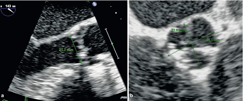
Fig. 27.2
(a and b) Transthoracic echocardiographic images of the annulus measurement from sinus to commissure
In addition to being aware of the anatomy of the aortic valve, it is imperative to understand the relationship of the valve to the surrounding structures: in particular, the coronary arteries, sinuses of valsalva, membranous septum, and mitral valve.
The coronary arteries are located in the anteriorly located right and left sinuses of Valsalva. During transcatheter valve procedures, the location of the coronary arteries is of vital importance in order to minimize the risk of coronary obstruction by the native valve during deployment of the bioprosthetic valve. A study of individuals with aortic stenosis undergoing multi-slice computed tomography (CT) demonstrated that the mean distance from the level of the basal attachment point of the aortic valve leaflets to the ostium of the left coronary and right coronary artery was 14.4 ± 2.9 mm and 17.2 ± 3.3 mm, respectively [2]. Current recommendations for minimum distance to the coronary arteries are 14 mm to prevent coronary obstruction. Measurement of coronary artery distance from the valve is only part of the story of coronary obstruction, another important factor being the width of the sinuses of Valsalva. Care must be taken to ensure that there is adequate room for displacement of the native leaflets prior to TAVR. This may be assessed by angiography or multi-slice CT or even during balloon valvuloplasty in case of contradictory results.
The final anatomic considerations include the relationship between the aortic valve and mitral valve and the conduction system. The mitral valve is in fibrous continuity with the aortic valve and is located posterior to the aorta with the anterior mitral leaflet lying in close proximity to the left ventricular outflow tract. Suboptimal positioning of the transcatheter valve prosthesis low in the left ventricular outflow tract could impinge on the movement and function of the anterior mitral leaflet. Location of the conduction system is another important concern in light of relatively high rates of pacemaker post-TAVR that are not fully understood. In fact, the atrioventricular node is located near the membranous septum of the left ventricle and therefore is neighboring the aortic valve. This relationship likely explains the rates of pacemaker implantation following aortic valve surgery. Therefore, it is not unreasonable to assume that implantation of a transcatheter valve in this region could also impact the development of conduction system abnormalities. Multiple theories exist regarding contribution to development of new conduction system disturbances including the depth of prosthesis implant. A retrospective study of 70 patients undergoing TAVR identified depth of implant and preexisting right bundle branch block as potential risk factors for permanent pacemaker implantation [3]. Other theories include the volume of calcification of the device landing zone which may create a mass effect or pressure on the conduction system in that region post device deployment [4].
Patient Selection
At present, transcatheter valve therapy, with the Edwards SAPIEN THV, has been approved by the Food and Drug Administration (FDA) for the treatment of aortic stenosis in high-risk patients, those who are not eligible for open-heart surgery for replacement of their aortic valve and have a “calcified aortic annulus (calcium buildup in the fibrous ring of the aortic heart valve).” It is also advised that a heart surgeon should be involved in determining if the SAPIEN THV is an appropriate treatment for the patient [5].
In practical terms, high-risk patients are those in whom the surgical risk is felt to be prohibitive. These patients are those defined in PARTNER A [6], patients at high risk for operative complications or death on the basis of coexisting conditions that were associated with a risk of death of at least 15 % by 30 days after the procedure or Society of Thoracic Surgeons (STS) Score of at least 10 %. The STS Score is a risk prediction model based on an algorithm that utilizes coexisting illnesses to predict the risk of mortality following surgical intervention. There is however a fine and poorly defined line between high risk due to comorbidities and too sick due to comorbidities. Differentiating between the two is the focus of ongoing investigation into identifying markers of frailty that may help aid the decision-making process. Gait speed is one such marker of morbidity, disability, and survival in older patients and has been shown to predict mortality and length of stay in patients undergoing cardiac surgery [7]. Recent work into the assessment of frailty using gait speed in patients undergoing evaluation for transcatheter aortic valve implantation demonstrated a high prevalence of slow gait speed in these patients. Furthermore, this marker of frailty was not accurately predicted by traditional methods of patient risk assessment [8]. For the time being, it is important to realize the limitations of conventional risk assessment tools and perhaps incorporate new markers of frailty in the overall patient evaluation. The ideal candidate is likely the elderly patient with multiple comorbidities but yet a reasonable quality of life that is expected to improve following intervention.
Once a patient is confirmed to be a high-risk surgical candidate, further investigations are required to establish the anatomic suitability of the patient for intervention. This requires careful investigation with echocardiography, coronary angiography, and evaluation of vascular access most commonly performed using multi-slice computed tomography (CT).
Echocardiographic Evaluation
Echocardiographic evaluation of aortic stenosis prior to TAVR involves confirmation of the presence of severe aortic stenosis as well as an assessment of left ventricular function and the existence of other associated valvular abnormalities such as mitral regurgitation that may have an impact during the procedure. In addition, the aortic annulus is evaluated by echo. As described previously, the annular dimension as estimated by echo must be done carefully to avoid underestimation from oblique measurements. This is best done in the parasternal long-axis view and by measuring from commissure to sinus rather than obliquely from sinus to sinus (Fig. 27.2). The assessment of pulmonary hypertension provides additional information of patient risk.
Coronary Angiography
Coronary angiography is an essential part of the assessment process for TAVR. The key role is to establish the presence of coronary artery disease and evaluate coronary artery grafts if present. The decision to intervene on existing coronary disease is debatable, and many experts suggest only intervening in the presence of prognostic lesions or in symptomatic patients. The presence of coronary artery disease appears to be associated with a worse prognosis. Data from a recent review of feasibility study data demonstrated that previous coronary artery bypass grafting (CABG) or percutaneous coronary intervention (PCI) was associated with a tenfold higher mortality at 30 days and a twofold higher mortality at any time following TAVI [9]. In addition to coronary evaluation, invasive angiography can be used to verify the measurements of the peripheral vessels and aorta using a marker pigtail.
Multi-slice CT
Computed tomography (CT) has become an almost essential component of patient evaluation pre-TAVR. This one technique can provide invaluable information on annular geometry and measurements and aortic dimensions as well as assess iliofemoral access, including tortuosity and calcification (Fig. 27.3).
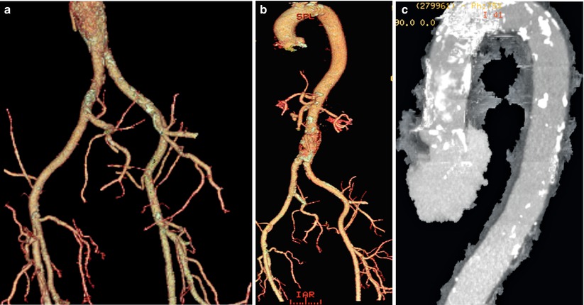

Fig. 27.3
(a) CT image of the iliac and femoral vessels demonstrating calcification and tortuosity. (b) Volume rendered CT image of the aorta and peripheral vessels. (c) CT image of the aorta demonstrating calcification in the ascending and transverse segments
The aortic annulus is a complex structure as previously described. Reconstruction of CT data allows an understanding of the oval geometry of the annulus and provides both the minimum and maximum diameters. In fact, in comparison with TTE, CT has been found to be more accurate in assessment of oval annuli and closely approximates results obtained from intraoperative TEE [10, 11]. In addition, CT enables accurate measurement of the height of the coronary artery ostia in relation to the annulus, which is crucial in minimizing risks of coronary artery obstruction. Aortic root measurements can also be easily obtained and are of particular importance for implantation of the Medtronic CoreValve, which is contraindicated in a very dilated ascending aorta (>45 mm).
Finally, thorough evaluation of the peripheral vasculature is best obtained using CT that permits visualization of the burden and distribution of calcium in the vessels as well as allowing reconstruction demonstrating the tortuosity of the vessels. In addition, CT can identify other high-risk features including dissections and complex atheroma in the aorta [12].
Balloon-Expandable Prosthesis: Edwards SAPIEN THV
The Edwards SAPIEN THV (Edwards LifeSciences) is a balloon-expandable transcatheter aortic valve (Fig. 27.4). The valve consists of a bovine trileaflet pericardial valve housed within a stainless steel stent (cobalt chromium in the case of the SAPIEN XT). A pericardial skirt to prevent paravalvular leaks at the annular level covers a portion of the stent. The device is deployed retrogradely via the aorta by balloon expansion during rapid ventricular pacing. The device is available in three sizes, 23, 26, and 29 mm, which can only be used via the transapical route. These valves can treat a native annulus of between 18 and 26 mm. The femoral delivery catheter, referred to as the RetroFlex 3, has an internal diameter of either 22 or 24French requiring a femoral access of a minimum of 8 mm. The newer generation devices (SAPIEN XT) available outside the United States have an internal diameter of 16 or 18French [13].
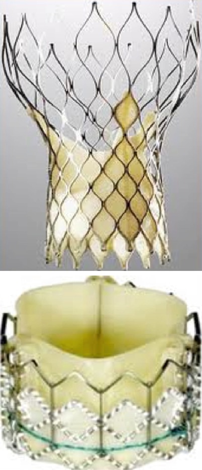

Fig. 27.4
Medtronic CoreValve (left) and Edwards SAPIEN (right) THV
Self-Expanding Aortic Prosthesis: Medtronic CoreValve
The Medtronic CoreValve Revalving System consists of three components: CoreValve bioprosthesis, the delivery catheter, and the disposable loading system.
The CoreValve bioprosthesis is a porcine pericardial valve sutured into a self-expandable nitinol frame. The nitinol frame is made of laser cut nitinol with diamond cells and a distinct funnel-like shape that measures between 53 and 55 mm in length. The frame has three distinct regions of radial force at the distal, mid, and outflow portion of the device. The distal portion of the device has high radial force to maintain intra-annular anchoring and is covered with a pericardial skirt to minimize paravalvular aortic regurgitation. The mid portion is constrained at the level of the porcine pericardial leaflets and is designed to avoid impingement of the coronary arteries while providing supra-annular leaflet function. The outflow portion of the prosthesis has low radial force and provides a means of orienting the device in the ascending aorta (Fig. 27.5). The valve leaflets are composed of six separate segments of porcine pericardium that are sutured to the frame in a supra-annular position. The supra-annular position reduces leaflet stress and optimizes leaflet motion [14]. In addition, it ensures optimal valve function despite inadequate frame expansion as described by Jilaihawi et al. [15]. The valve is currently available in three sizes, all of which utilize the same 18French delivery catheter: 26, 29, and 31 mm to treat aortic annuli between 20 and 29 mm.
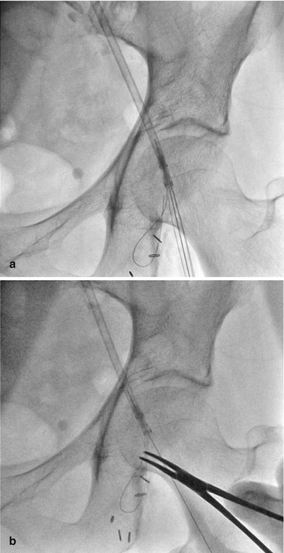

Fig. 27.5
(a and b) Outflow portion of the CoreValve prosthesis has low radial force and provides a means of orienting the device in the ascending aorta
TAVR Procedure: A Step-by-Step Guide
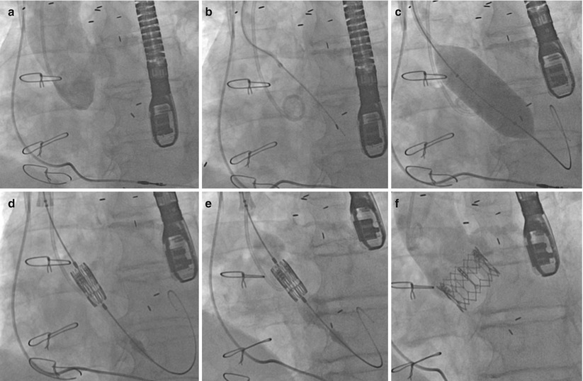
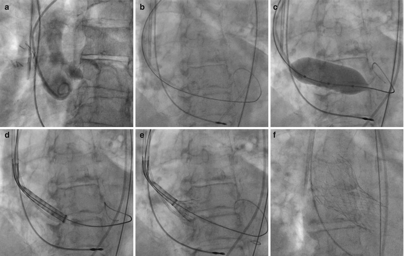
There are two currently available devices for TAVR, the Edwards SAPEIN THV and the Medtronic CoreValve (Figs. 27.6 and 27.7). The two devices differ in their means of deployment and the specifics for each will be discussed in more detail following this section which deals with basic steps of the procedure with tips and tricks discussed along the way.
Get Clinical Tree app for offline access

Fig. 27.6
(a) Aortogram pre-TAVI. (b) Crossing the aortic valve using an AL1 catheter and straight-tipped wire. (c) Aortic valvuloplasty. (d) Positioning of the Edwards SAPIEN valve. (e) Balloon inflation of the Edwards SAPIEN valve. (f) Final angiographic result

Fig. 27.7
Deployment of the Medtronic CoreValve. (a) Initial aortogram. (b


Stay updated, free articles. Join our Telegram channel

Full access? Get Clinical Tree


