Upper Limb I: Shoulder Girdle


Upper Limb I: Shoulder Girdle


Shoulder Girdle

Trauma to the shoulder girdle is common throughout life, but the site of injury varies with age. In children and adolescents, fracture of the clavicle sustained during play or athletic activities is a frequent type of skeletal injury. Dislocations of the shoulder and acromioclavicular separation are often seen in the third and fourth decades of life, whereas fracture of the proximal humerus is commonly encountered in the elderly. Most of these traumatic conditions can be diagnosed on the basis of history and clinical examination, with radiographs obtained mainly to define the exact site, type, and extent of the injury. At times, however, as in posterior dislocation in the glenohumeral joint, for example, which is the most commonly missed diagnosis in shoulder trauma, only radiographic examination performed in the proper projections may reveal the abnormality.


Anatomic-Radiologic Considerations

The shoulder girdle consists of osseous components—proximal humerus, scapula, and clavicle, forming the glenohumeral and acromioclavicular joints (Fig. 5.1)—and various muscles, ligaments, and tendons reinforcing the joint capsule (Fig. 5.2). The joint capsule inserts along the anatomic neck of the humerus and along the neck of the glenoid. In front, it is reinforced by three glenohumeral ligaments (GHLs) (the superior, middle, and inferior), which converge from the humerus to be attached by the long head of the biceps tendon to the supraglenoid tubercle. The other important ligaments are the acromioclavicular, coracoacromial, and the coracoclavicular (including trapezoid and conoid portions) (see Fig. 5.2A).

The essential muscles are those that form the rotator cuff (Fig. 5.3). The term rotator cuff is used to describe the group of muscles that envelop the glenohumeral joint, holding the head of the humerus firmly in the glenoid fossa. They consist of the subscapularis anteriorly, the infraspinatus posterosuperiorly, the teres minor posteriorly, and the supraspinatus superiorly (mnemonic SITS). The subscapularis muscle inserts on the lesser tuberosity anteriorly. The insertions of the supraspinatus, infraspinatus, and teres minor muscles are on the greater tuberosity, posteriorly. The supraspinatus tendon covers the superior aspect of the humeral head, inserting on the superior facet of the greater tuberosity. The infraspinatus tendon covers the superior and posterior aspects of the humeral head and inserts on the middle facet, located distal and more posterior to the superior facet. The teres minor is lower in position and inserts on the posteroinferior facet of the greater tuberosity (Fig. 5.3B). In addition, the long head of the biceps with its tendon, which in its intracapsular portion runs through the joint, and the triceps muscle, inserting on the infraglenoid tubercle inferiorly, provide additional support to the glenohumeral joint.

Most trauma to the shoulder area can be sufficiently evaluated on radiographs obtained in the anteroposterior projection with the arm in the neutral position (Fig. 5.4A) or with the arm internally or externally rotated to visualize different aspects of the humeral head. The one limitation of these views is that the humeral head is seen overlapping the glenoid, thereby obscuring the glenohumeral joint space (Fig. 5.4B). Eliminating the overlap can be accomplished by rotating the patient approximately 40 degrees toward the affected side. This special posterior oblique view, known as the Grashey projection, permits the glenoid to be seen in profile (Fig. 5.5) and is thus particularly effective in demonstrating suspected posterior dislocation. Obliteration of the normally clear space between the humeral head and the glenoid margin on this view confirms the diagnosis (see Figs. 5.54 and 5.56).

Other special views have proved to be useful in evaluating suspected trauma to various aspects of the shoulder. A superoinferior view of the shoulder, known as the axillary projection, is helpful in determining the exact relationship of the humeral head and the glenoid fossa (Fig. 5.6), as well as in detecting anterior or posterior dislocation. This view, however, may at times be difficult to obtain, particularly if the patient is unable to abduct the arm, in which case a variant of the axillary projection known as the West Point view may be similarly effective. In addition to all the benefits of the axillary projection, the West Point view effectively demonstrates the anteroinferior rim of the glenoid (Fig. 5.7). Another useful variant of the axillary projection is the Lawrence view. The importance of this projection lies in the fact that it does not require full abduction of the arm, because it can be compensated for by angulation of the radiographic tube (Fig. 5.8). Suspected trauma to the proximal humerus, which can be demonstrated on the anteroposterior or the transscapular projection (see Fig. 5.12), may require the transthoracic lateral view for sufficient evaluation (Fig. 5.9). Because this projection provides a true lateral view of the proximal humerus, it is particularly valuable in determining the degree of displacement or angulation of the osseous fragments (see Fig. 5.28B). When trauma to the bicipital groove is suspected, a tangent radiograph of this structure is required (Fig. 5.10). Injury to the acromioclavicular articulation is usually evaluated on the anteroposterior view obtained with a 15-degree cephalad tilt of the radiographic tube (Fig. 5.11). Stress views in this projection, for which weights are
strapped to the patient’s forearms, are often mandatory, especially in suspected occult acromioclavicular subluxation (see Fig. 5.78). Fracture of the scapula may require a transscapular (or Y) view for sufficient evaluation (Fig. 5.12). Fracture of the acromion can be adequately evaluated on the shoulder outlet view. This projection is obtained similarly to the Y view of the shoulder girdle; however, the central beam is directed toward the superior aspect of the humeral head and is angled approximately 10 to 15 degrees caudad (Fig. 5.13). This view is also effective in demonstration of morphologic types of the acromion (Fig. 5.14; see also Fig. 5.24).


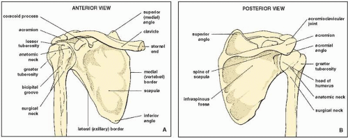
FIGURE 5.1 Osseous structures of the shoulder. Anterior (A) and posterior (B) views of the osseous components of the shoulder girdle.

Ancillary imaging techniques are usually used to evaluate injury to the cartilage and soft tissues of the shoulder. The most frequently used modalities are arthrography and magnetic resonance imaging (MRI). Arthrography can be performed using a single- or double-contrast technique (Fig. 5.15). In cases of suspected tear of the rotator cuff, for example, a single-contrast arthrogram may reveal abnormal communication between the glenohumeral joint cavity and the subacromial-subdeltoid bursae complex, which is diagnostic of this abnormality (see Fig. 5.60C). Although it is difficult to prescribe for which conditions a single- as opposed to a double-contrast study should be chosen, the latter may be better suited to demonstrate abnormalities of the articular cartilage and capsule, as well as the presence of osteochondral bodies in the joint. A double-contrast study, however, is always indicated when arthrography is to be combined with CT scan (computed arthrotomography) for evaluating suspected abnormalities of the fibrocartilaginous glenoid labrum (Fig. 5.16). The effectiveness of this combination lies in the fact that the injected air outlines the
anterior and posterior labrum for better demonstration of subtle traumatic changes on CT images. For this study, the patient is placed supine in the CT scanner with the arm of the affected side in the neutral position to allow the air to rise and enhance the outline of the anterior labrum. To evaluate the posterior labrum, the arm is externally rotated (or the patient is positioned prone) to force the air to move posteriorly.


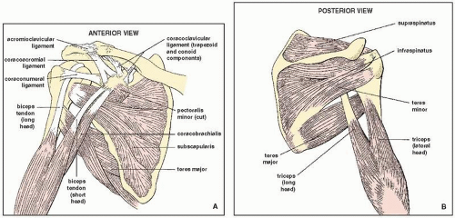
FIGURE 5.2 Muscles, ligaments, and tendons of the shoulder. Anterior (A) and posterior (B) views of the muscles, ligaments, and tendons of the shoulder girdle. (Modified from Middleton WD, Lawson TL, 1989, with permission.)


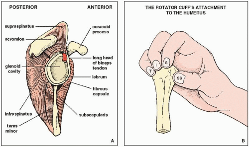
FIGURE 5.3 Rotator cuff. (A) Schematic of the glenoid fossa (with the humerus removed) shows the location of the muscles of the rotator cuff and the intracapsular portion of the long head of the biceps tendon. (B) Four muscles form the “rotator cuff”: subscapularis (SS), supraspinatus (S), infraspinatus (I), and teres minor (T). They envelop the joint, blend with the capsule, and grasp their four points of attachment to the humerus, as does the hand in the figure, thus maintaining the integrity of the joint. (Modified from Anderson JE, 1983, with permission.)


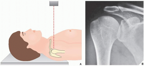
FIGURE 5.4 Anteroposterior view. (A) For the standard anteroposterior projection of the shoulder, the patient may be either supine, as shown here, or erect; the arm of the affected side is fully extended in the neutral position. The central beam is directed toward the humeral head. (B) On the radiograph obtained in this projection, the humeral head is seen overlapping the glenoid fossa. The glenohumeral joint is not well demonstrated.


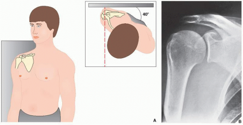
FIGURE 5.5 Grashey view. (A) For the anteroposterior view of the shoulder that demonstrates the glenoid in profile (Grashey projection), the patient may be either erect, as shown here, or supine. He or she is rotated approximately 40 degrees toward the side of the suspected injury, and the central beam is directed toward the glenohumeral joint. (B) The radiograph in this projection (posterior oblique view) shows the glenoid in true profile. Note that the glenohumeral joint space is now clearly visible.


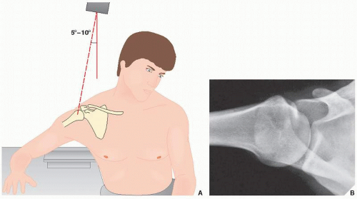
FIGURE 5.6 Axillary view. (A) For the axillary view of the shoulder, the patient is seated at the side of the radiographic table, with the arm abducted so that the axilla is positioned over the film cassette. The radiographic tube is angled approximately 5 to 10 degrees toward the elbow, and the central beam is directed through the shoulder joint. (B) The film in this projection demonstrates the exact relationship of the humeral head and the glenoid.


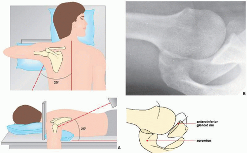
FIGURE 5.7 West Point view. (A) For the West Point view of the shoulder, the patient lies prone on the radiographic table, with a pillow placed under the affected shoulder to raise it approximately 8 cm. The film cassette is positioned against the superior aspect of the shoulder. The radiographic tube is angled toward the axilla at 25 degrees to the patient’s midline and 25 degrees to the table’s surface. (B) On the radiograph in this projection, the relationship of the humeral head and the glenoid can be as sufficiently evaluated as on the axillary view, but the anteroinferior glenoid rim, which is seen tangentially, is better visualized.


FIGURE 5.8 Lawrence view. For the Lawrence variant of the axillary view of the shoulder, the patient lies supine on the radiographic table, with the affected arm abducted up to 90 degrees. The film cassette is positioned against the superior aspect of the shoulder with the medial end against the neck, which places the midportion of the cassette level with the surgical neck of the humerus. The radiographic tube is at the level of the ipsilateral hip and is angled medially toward the axilla. The amount of angulation depends on the degree of abduction of the arm: Less abduction requires increased medial angulation. The central beam is directed horizontally slightly superior to the midportion of the axilla. The Lawrence view demonstrates the same structures as the standard axillary view.


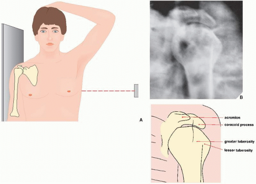
FIGURE 5.9 Transthoracic lateral view. (A) For the transthoracic lateral projection of the proximal humerus, the patient is erect with the injured arm against the radiographic table. The opposite arm is abducted so that the forearm rests on the head. The central beam is directed below the axilla, slightly above the level of the nipple. (B) The radiograph obtained in this projection demonstrates the true lateral view of the proximal humerus.


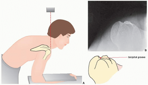
FIGURE 5.10 Bicipital groove view. (A) For a tangent film in the superoinferior projection visualizing the bicipital groove (sulcus), the patient is standing and leaning forward, with the forearm resting on the table and the hand in supination. The film cassette rests on the patient’s forearm. The central beam is directed vertically toward the bicipital groove, which has been marked on the skin. (B) On the radiograph obtained in this projection, the bicipital groove is clearly demonstrated.


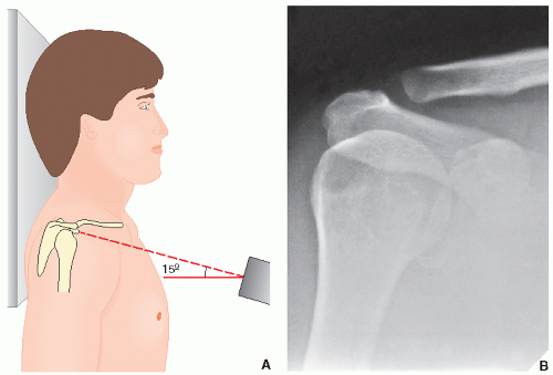
FIGURE 5.11 Acromioclavicular view. (A) To evaluate the acromioclavicular articulation, the patient is erect, with the arm of the affected side in the neutral position. The central beam is directed 15 degrees cephalad toward the clavicle. As overexposure of the film will make it difficult to evaluate the acromioclavicular joint properly, the radiographic factors should be reduced to approximately 33% to 50% of those used in obtaining the standard anteroposterior view of the shoulder. (B) The radiograph obtained in this projection shows the normal appearance of the acromioclavicular joint.


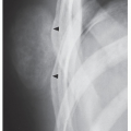
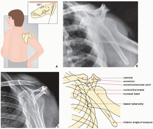
FIGURE 5.12 Transscapular view. (A) For the transscapular (or Y) projection of the shoulder girdle, the patient is erect, with the injured side against the radiographic table. The patient’s trunk is rotated approximately 20 degrees from the table to allow for separation of the two shoulders (inset). The arm on the injured side is slightly abducted and the elbow flexed, with the hand resting on the ipsilateral hip. The central beam is directed toward the medial border of the protruding scapula. (This view may also be obtained with the patient lying prone on the radiographic table and the uninjured arm elevated approximately 45 degrees.) (B) The radiograph obtained in this projection provides a true lateral view of the scapula, as well as an oblique view of the proximal humerus. (C) Same structures can be visualized on the radiograph obtained without abduction of the arm.


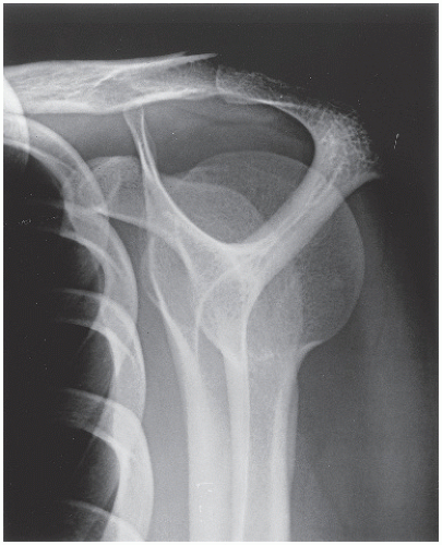
FIGURE 5.13 Outlet view. This projection shows the | same anatomic structures as demonstrated on the Y view of the shoulder girdle. In addition, coracoacromial arch and space occupied by the rotator cuff are well imaged.


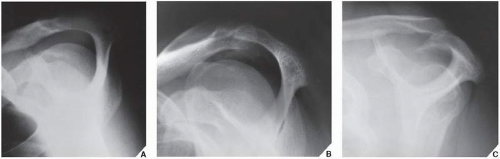
FIGURE 5.14 Types of the acromion. On the outlet view of the shoulder, three morphologic types of acromion are well demonstrated. (A) Type I (flat). (B) Type II (curved). (C) Type III (hooked). Recently reported a very rare Type IV (convex undersurface) is not shown here.


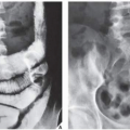
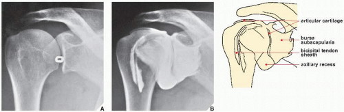
FIGURE 5.15 Arthrography of the shoulder. For arthrographic examination of the shoulder, the patient is positioned supine on the radiographic table, with the unaffected shoulder slightly elevated and the affected arm in external rotation with the palm up. (A) With the aid of fluoroscopy, a lead marker is placed near the lower third of the glenohumeral articulation to indicate the site of needle insertion. Under fluoroscopic control, 15 mL of positive contrast agent (60% diatrizoate meglumine or another meglumine-type medium) is injected into the joint capsule. The usual study includes supine films of the shoulder in the standard anteroposterior (arm in the neutral position and in internal and external rotation) and the axillary projections. (B) A normal arthrogram of the shoulder shows contrast outlining the articular cartilage of the humerus and the glenoid and filling the axillary pouch, the subscapularis recess, and the bicipital tendon sheath.


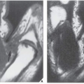
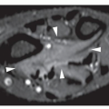
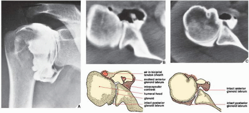
FIGURE 5.16 Tear of the glenoid labrum. As the result of an auto accident, a 33-year-old woman sustained an injury to the right shoulder; she presented with pain and limitation of motion in the joint. Standard films of the shoulder were normal. As injury to the cartilaginous labrum was suspected, double-contrast arthrography was performed. Five milliliters of positive contrast agent and 10 mL of room air were injected into the joint capsule. (A) This arthrogram shows no evident abnormalities. The subscapularis recess, which is not opacified on this view, was shown later in the study to fill with contrast. (B) In conjunction with arthrography, a CT scan of the same shoulder was performed and clearly demonstrates avulsion of the anterior glenoid labrum, a finding not appreciated on the arthrographic study. Note that the avulsed fragment is surrounded by air and shows absorption of the contrast agent. (C) The normal appearance of the glenoid labrum is shown for comparison.

Recent studies have shown the considerable advantage of MRI in the examination of the shoulder. This modality is particularly effective in demonstrating traumatic abnormalities of the soft tissues, such as impingement syndrome, partial and complete rotator cuff tears, biceps tendon rupture, glenoid labrum tears, and demonstration of the traumatic joint effusion. However, the shoulder presents unique difficulties for imaging. Because of space limitations in the magnet, the shoulder frequently cannot be positioned in the center of the magnetic field. This necessitates lateral shift for image centering and scanning a region where the signal-to-noise ratio is relatively low. These problems have been overcome by combining high-resolution scanning with the use of special surface coils. Because the bones and muscles of the shoulder girdle are oriented along multiple nonorthogonal axes, scanning in oblique planes is more effective.

The patient should be positioned in the magnet supine with the arms along the thorax and the affected arm externally rotated. The scanning planes include oblique coronal (along the long axis of the belly of the supraspinatus muscle), oblique sagittal (perpendicular to the course of supraspinatus muscle), and axial (Fig. 5.17). The first two planes are ideal for evaluating all the structures of the rotator cuff; the axial plane is ideal for evaluating the glenoid labrum, bicipital groove, biceps tendon, and subscapularis tendon. Appropriate pulse sequences are critical in displaying normal anatomy and traumatic abnormalities. T1-weighted pulse sequences sufficiently demonstrate the structural anatomy (Figs. 5.18 and 5.19). Proton density and T2-weighted pulse sequences provide the information necessary to evaluate pathology of rotator cuff, joint space, and bones (see Figs. 5.62, 5.63, 5.64B, and 5.65).

The demonstration of rotator cuff muscles and tendons is greatly facilitated by the use of MRI. The supraspinatus is best demonstrated on oblique coronal and sagittal images, preferably obtained on spin-echo T1-weighted sequences. It is seen as a thick, intermediate-intensity structure, and its tendon inserts on the superolateral aspect of the greater tuberosity of the humerus (Fig. 5.18, see also Fig. 5.26). The infraspinatus and subscapularis are best demonstrated on axial images as fusiform, intermediate-intensity structures. The infraspinatus tendon inserts distally and more posterior to the supraspinatus on the greater tuberosity, adjacent to the insertion of teres minor (see Fig. 5.26). The subscapularis muscle is located anterior to the body of the scapula. It appears on T1-weighted axial images as an intermediate-intensity structure that tapers anteriorly into a low-intensity tendon, where it merges with the anterior aspect of the capsule before inserting on the lesser tuberosity (Fig. 5.19, see also Fig. 5.26).

The axial images are effective in demonstration of the joint capsule, which is anteriorly reinforced by the anterior GHLs. The capsular complex provides stabilization of the glenohumeral joint. The anterior capsular complex includes the fibrous capsule, the anterior GHLs, the synovial membrane and its recesses, the fibrous glenoid labrum, the subscapularis muscle and tendon, and the scapular periosteum. Three types of anterior capsular insertion have been identified by Zlatkin and colleagues. They are determined by the proximity of insertion to the glenoid margin (Fig. 5.20). In type I, the capsule inserts on the glenoid rim in close proximity to the glenoid labrum. In types II and III, the capsular insertion is further away from the glenoid rim and may reach the scapular neck (Fig. 5.21). The further the anterior capsule inserts from the glenoid margin, the more unstable the glenohumeral joint will be. The posterior portion of the capsule shows no variations and attaches directly to the labrum. The axial images are also effective in the demonstration of anterior and posterior cartilaginous labrum of the glenoid, which are seen as two small triangles of low signal intensity that are located anteriorly and posteriorly to the glenoid margin (Fig. 5.22). The superior and inferior aspects of the labrum are best demonstrated on
the oblique coronal sections (Fig. 5.23). There are numerous imaging variations of the morphology of the cartilaginous labrum. The most common shape is triangular as illustrated in Figure 5.22. The second most common shape is round. The other morphologic variations include the flat labrum and the cleaved or notched labrum. On rare occasions, the anterior and posterior labrum may be absent. Furthermore, there are appearances resembling labral tears, such as undercutting of the labrum by hyaline cartilage, sublabral holes or recesses, and Buford complexes (see Fig. 5.74).


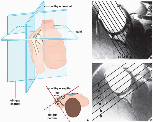
FIGURE 5.17 MRI of the shoulder. (A) Standard planes of MRI sections of the shoulder. (B) Oblique coronal sections are obtained parallel to the long axis of the supraspinatus muscle. (C) Oblique sagittal sections are obtained perpendicular to the coronal sections. (From Beltran J, 1990, with permission.)


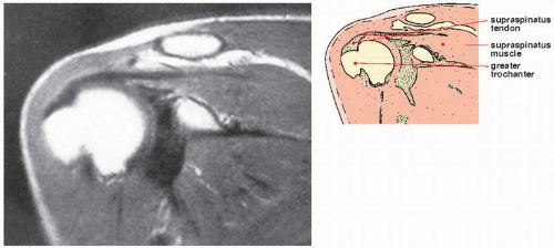
FIGURE 5.18 MRI of the shoulder. T1-weighted oblique coronal image of the right shoulder demonstrates a normal supraspinatus muscle and tendon attaching to the greater tuberosity of the humerus. (From Holt RG et al., 1990, with permission.)


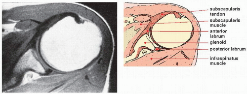
FIGURE 5.19 MRI of the shoulder. T1-weighted axial image of the left shoulder demonstrates a normal subscapularis muscle and tendon and the infraspinatus muscle.

The sagittal images are useful in demonstration of morphologic variations of the acromion. Three types of acromion have been identified by Bigliani and coworkers. Type I shows a flat undersurface, type II a curved undersurface, type III a hooked undersurface, and type IV a convex undersurface (Figs. 5.24 and 5.25). Type III acromion is considered to be associated with tears of the rotator cuff proximal to the site of insertion of the supraspinatus tendon to the greater tuberosity of the humerus. Sagittal images also effectively demonstrate the muscles of the rotator cuff and their tendons (Fig. 5.26).

In the past decade, direct MR arthrography (MRa) using injection of contrast solution into the shoulder joint gained worldwide acceptance. This technique is particularly effective for demonstrating labral-ligamentous abnormalities and distinguishing partial-thickness from full-thickness tears of the rotator cuff. A variety of concentrations and mixtures of solutions are used by different radiologists. In our institution, we follow the recommendation reported by Steinbach and colleagues. We add 0.8 mL of gadopentetate dimeglumine (gadolinium with strength 287 mg/mL) to 100 mL of normal saline solution. Subsequently, we mix 10 mL of this solution with 5 mL of 60% meglumine diatrizoate (iodinated contrast) and 5 mL of 1% lidocaine, which gives a final gadolinium dilution ratio of 1:250. From 12 to 15 mL of this mixture is then injected into the shoulder joint using fluoroscopic guidance in a similar fashion as for conventional shoulder arthrography (see Fig. 5.15). Multiple pre-exercise and postexercise radiographic spot images are obtained in neutral position and in external and internal rotation of the arm. Subsequently, without delay, the patient undergoes MRI examination using similar scanning planes as for a conventional MR study. If glenoid labrum abnormalities are suspected, additional sequences are obtained in so-called ABER (abduction and external rotation) position.


FIGURE 5.20 Capsule of the shoulder joint. Three types of anterior capsular insertion to the scapula.

During evaluation of MRI of the shoulder, it is helpful to use a checklist as provided in Table 5.1.


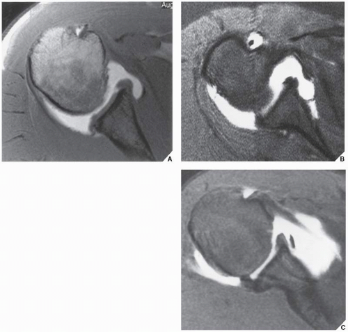
FIGURE 5.21 Capsular insertion to glenoid margin. (A) Axial T1-weighted image after intraarticular injection of gadolinium shows type I of anterior capsular insertion. (B) Axial fast spin-echo image with fat saturation and intraarticular gadolinium shows type II of anterior capsular insertion. (C) Axial T1-weighted image with fat saturation and intraarticular gadolinium shows type III of anterior capsular insertion.


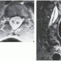
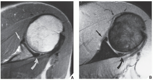
FIGURE 5.22 Fibrocartilaginous labrum of the glenoid. (A) Axial T1-weighted and (B) axial T2-weighted (multiplanar gradient-recalled [MPGR]) MR images show anterior (arrows) and posterior (curved arrows) labra as small triangles of low signal intensity.


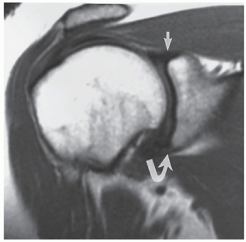
FIGURE 5.23 Fibrocartilaginous labrum. Oblique coronal T1-weighted MRI shows a superior (arrow) and inferior (curved arrow) labra.


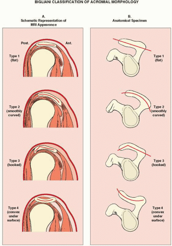
FIGURE 5.24 Variations of the acromial morphology. Schematic representation of morphologic variations of the acromion. (A) MRI appearance on oblique sagittal sections. (B) Appearance on anatomical specimen.


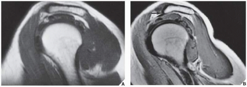
FIGURE 5.25 Morphologic variations of the acromion. (A) In the sagittal oblique plane, type II acromion shows a mild curved undersurface. (B) Type III acromion demonstrates a hooked undersurface (arrow).


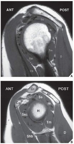
FIGURE 5.26 Muscles and their tendons of the shoulder girdle as visualized on sagittal MRI. (A) Lateral section, (B) medial section. H, Humeral head; Ac, acromion; Cl, clavicle; Cp, coracoid process; D, deltoid; Ss, supraspinatus; Is, infraspinatus; Ssc, subscapularis; Tm, teres minor; Shb, short head of the biceps; Lhb, long head of the biceps; Cb, coracobrachialis.


TABLE 5.1 Checklist for Evaluation of MRI and MRa of the Shoulder


Osseous Structures


Humeral head (c, s, a)


Glenoid (c, s, a)


Acromion (c, s)


Clavicle (c, s)


Coracoacromial arch (s)


Cartilaginous Structures


Articular cartilage (c, s, a)


Fibrocartilaginous labrum, anterior, posterior, superi or, inferior (c, a)


Joints


Glenohumeral (c, a)


Acromioclavicular (c)


Capsule


Attachement (a)


Laxity (a)


Muscles and Their Tendons


Supraspinatus (c, s, a)


Infraspinatus (c, s, a)


Teres minor (c, s)


Subscapularis (s, a)


Biceps—long head (c, s, a)


Deltoid (c, a)


Ligaments


Superior glenohumeral (s, a)


Middle glenohumeral (s, a)


Inferior glenohumeral (s, a)


Coracohumeral (c)


Coracoclavicular—conoid and trapezoid (s)


Coracoacromial (s)


Acromioclavicular (c)


Bursae


Subacromial (c)


Subdeltoid (c)


Other Structures


Rotator interval—space between supraspinatus and subscapularis (s)


Quadrilateral space (s, a)


Suprascapular notch (c, a)


Spinoglenoid notch (c, a)


The best imaging planes for visualization of listed structures are given in parenthesis; c, coronal; s, sagittal; a, axial


TABLE 5.2 Standard and Special Radiographic Projections for Evaluating Injury to the Shoulder Girdle


Projection


Demonstration


Anteroposterior


Arm in neutral position


Fracture of


Humeral head and neck


Clavicle


Scapula


Anterior dislocation


Bankart lesion


Erect


Fat-blood interface (FBI sign)


Arm in internal rotation


Hill-Sacks lesion


Arm in external rotation


Compression fracture of humeral head (trough line impaction) secondary to posterior dislocation


40-degree posterior oblique (Grashey)


Glenohumeral joint space


Glenoid in profile


Posterior dislocation


15-degree cephalad tilt of radiographi tube


Acromioclavicular joint


Acromioclavicular separation


Fracture of clavicle


Stress


Occult acromioclavicular subluxation


Acromioclavicular separation


Axillary


Relationship of humeral head and glenoid fossa


Anterior and posterior dislocations


Compression fractures secondary to anterior and posterior dislocations


Fractures of


Proximal humerus


Scapula


West Point


Same structures and conditions as axillary projection


Anteroinferior rim of glenoid


Lateral Transthoracic


Relationship of humeral head and glenoid fossa


Fractures of proximal humerus


Tangent (humeral head)


Bicipital groove


Transscapular (Y)


Relationship of humeral head and glenoid fossa


Fractures of


Proximal humerus


Body of scapula


Coracoid process


Acromion


Oblique (outlet)


Coracoacromial arch


Rotator cuff outlet


For a summary of the foregoing discussion in tabular form, see Tables 5.2 and 5.3 and Figure 5.27.


Injury to the Shoulder Girdle


Fractures About the Shoulder

Fractures of the Proximal Humerus. Fractures of the upper humerus involving the head, the neck, and the proximal shaft usually result either from a direct blow to the humerus or, as is more often seen in elderly patients, from a fall on the outstretched arm. Nondisplaced fractures are the most common, representing approximately 85% of all such proximal humeral injuries.

The anteroposterior projection is usually sufficient to demonstrate the abnormality, but the transthoracic lateral or the transscapular (or Y) projection may be required to provide a fuller evaluation, particularly of the degree of displacement or angulation of the osseous fragments (Fig. 5.28). The erect anteroposterior radiograph may demonstrate the presence of fat and blood within the joint capsule (the FBI sign of lipohemarthrosis; see Fig. 4.36A), indicating intraarticular extension of the fracture.

Traditional classifications of trauma to the proximal humerus, according to the level of the fracture or the mechanism of injury, have been inadequate to identify the various types of displaced fractures. The four-segment classification described by Neer in 1970 was complex and difficult to follow. He later modified this classification and simplified divisions to various groups. Classification of a displacement pattern depends on two main factors: the number of displaced segments and the key segment displaced. Fractures of the proximal humerus occur between one or all of four major segments: the articular segment (at the level of the anatomic neck), the greater tuberosity, the lesser tuberosity, and the humeral shaft (at the level of the surgical neck). One-part fracture occurs when there is minimal or no displacement between the segments. In two-part fractures, only one segment is displaced. In three-part fractures, two segments are displaced and one tuberosity remains in continuity with the humeral head. In four-part fractures, three segments are displaced, including both tuberosities. Two-part, three-part, and four-part fractures may or may not be associated with dislocation, either anterior or posterior. The involvement of the articular surface is classified separately into
two groups: the anterior fracture-dislocation, termed by Neer “head splitting,” and posterior fracture-dislocation, termed “impression” (Fig. 5.29).


TABLE 5.3 Ancillary Imaging Techniques for Evaluating Injury to the Shoulder Girdle


Technique


Demonstration


Tomography (almost completely replaced by CT)


Position of fragments and extension of fracture line in complex fractures


Healing process:


Nonunion


Secondary infection


Computed Tomography (CT)


Relationship of humeral head and glenoid fossa


Multiple fragments in complex fractures (particularly of scapula)


Intraarticular displacement of bony fragments in fractures


Magnetic Resonance Imaging (MRI)


Impingement syndrome


Partial and complete rotator cuff tear


Biceps tendon rupture


Glenoid labrum tears


Glenohumeral instability


Traumatic joint effusion


Subtle synovial abnormalities


Ultrasound (US)


Rotator cuff tear


Arthrography


Single- or double-contrast


Complete rotator cuff tear


Partial rotator cuff tear


Abnormalities of articular cartilage and joint capsule*


Synovial abnormalities*


Adhesive capsulitis


Osteochondral bodies in joint*


Abnormalities of bicipital tendon*


Intraarticular portion of bicipital tendon*


Inferior surface of rotator cuff*


Double-contrast combined with CT


All of the above and in addition:


Abnormalities of cartilaginous glenoid labrum


Osteochondral bodies in joint


Subtle synovial abnormalities


* These conditions are usually best demonstrated using double-contrast arthrography.

These features are best demonstrated on erect films.

These abnormalties are best demostraed on MRa.

Only gold members can continue reading. Log In or Register to continue

Stay updated, free articles. Join our Telegram channel

Jul 24, 2016 | Posted by in MUSCULOSKELETAL IMAGING | Comments Off on Upper Limb I: Shoulder Girdle

Full access? Get Clinical Tree

Get Clinical Tree app for offline access