Upper Limb II: Elbow


Upper Limb II: Elbow


Elbow

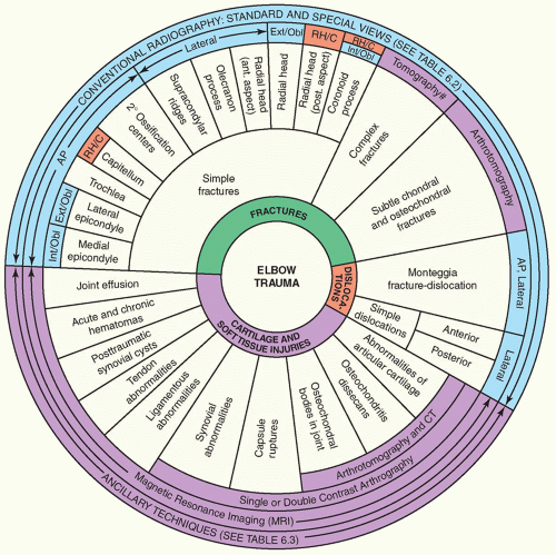
Trauma to the elbow is commonly encountered in all age groups but is particularly common in childhood when children, as toddlers, often sustain elbow injuries. Play and athletic activities in childhood and young adolescence are also frequent occasions of trauma. Although history and clinical examination usually provide clues to the correct diagnosis, radiologic examination is indispensable in determining the type of fracture or dislocation, the direction of the fracture line and the position of the fragments, and also in evaluating concomitant soft-tissue injuries.


Anatomic-Radiologic Considerations

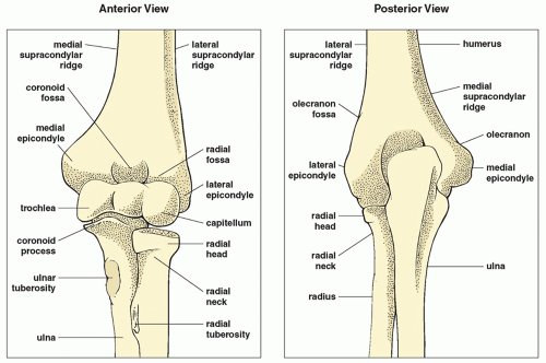
The elbow articulation, a compound synovial joint, comprises the humeroulnar (ulnatrochlear), the humeroradial (radiocapitellar), and the proximal radioulnar joints (Fig. 6.1). It is a hinged articulation with approximately 150 degrees of flexion from a completely extended position. The flexion and extension movements in the elbow occur in the ulnatrochlear and radiocapitellar joints. The biceps, brachioradialis, and brachialis muscles are the primary elbow flexors, while the triceps is the extensor of the elbow joint (
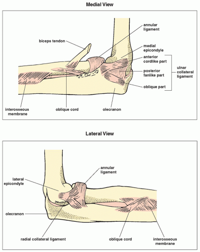
Fig. 6.2). Rotational movement occurs as the head of the radius, held tightly by the annular ligament of the ulna, rotates within the ulna’s radial notch. The proximal and distal radioulnar joints allow 90 degrees of pronation and supination of the forearm. The stability of the joint is ascertained by the group of ulnar collateral ligaments (UCLs) medially and radial collateral ligaments laterally (Fig. 6.3). The UCL consists of the anterior bundle, which extends from the anteroinferior aspect of the medial epicondyle to the medial coronoid margin; the posterior bundle, which extends from the posteroinferior aspect of the medial epicondyle to the medial olecranon margin; and the transverse bundle, which extends over the notch between the coronoid process and the olecranon. The radial collateral ligament is thinner than the UCL and inserts in the annular ligament, which in turn encircles the radial head and attaches to the anterior and posterior margins of the radial notch of the ulna. A fibrous capsule deep within the ligament structures surrounds the elbow joint. The anterior joint capsule and synovium insert proximally to the coronoid and radial fossae at the anterior aspect of the humerus. The posterior joint capsule attaches to the humerus just proximal to the olecranon fossa.

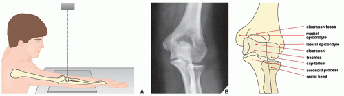
When trauma to the elbow is suspected, radiographs are routinely obtained in the anteroposterior and lateral projections, occasionally supplemented by internal and external oblique views.

The 
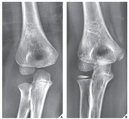
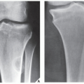
anteroposterior projection usually suffices to demonstrate an injury to the medial and the lateral epicondyles, the olecranon fossa, the capitellum, the trochlea, and the radial head (
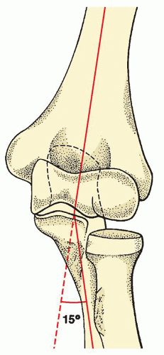
Fig. 6.4). It also reveals an important anatomic relation of the forearm to the central axis of the arm known as the carrying angle (Fig. 6.5). Normally, the long axis of the forearm forms a valgus angle of 15 degrees with the long axis of the arm; the forearm is thus angled laterally, that is, away from the central axis of the body.

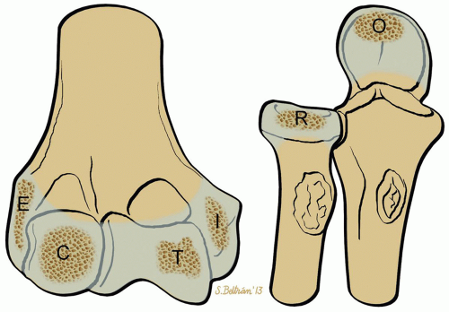
On the anteroposterior view in children, it is essential to recognize the four secondary ossification centers of the distal humerus: those of the capitellum, the medial and the lateral epicondyles, and the trochlea. The usual order in which these centers appear and the age at which they become radiographically visible are important factors in the evaluation of injuries to the elbow (Fig. 6.6). The displacement of any of these centers serves as a diagnostic indicator of the type of fracture or dislocation. For example, the medial epicondyle always ossifies before the trochlea. If radiographic examination in a child between the age of 4 and 8 years reveals a bony structure in the region of the trochlea (i.e., before this center of ossification should appear) and shows no evidence of the ossification center of the medial epicondyle, then it must be assumed that the ossification center of the medial epicondyle has been avulsed and displaced into the joint (Fig. 6.7). Some radiologists prefer to use a mnemonic “CRITOE 1-3-5-7-9-11” to determine the sequence and age of appearance of the six ossification centers around elbow joint: the capitellum, the radial head, the internal (medial) epicondyle, the trochlea, the olecranon, and the external (lateral) epicondyle (Figs. 6.8 and 6.9).

The lateral view of the elbow allows sufficient evaluation of the olecranon process, the anterior aspect of the radial head, and the humeroradial articulation. It is limited, however, in the information it can provide, particularly with respect to the posterior half of the radial head and the coronoid process, because of the overlap of osseous structures (Fig. 6.10).

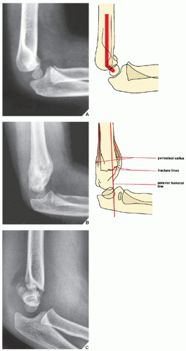
As with the anteroposterior projection, the lateral view in children reveals significant configurations and relations, which, if distorted, indicate the presence of an abnormality. The distal humerus in children has an angular appearance resembling a hockey stick, the angle of which normally measures approximately 140 degrees. Loss of this configuration occurs in supracondylar fracture (
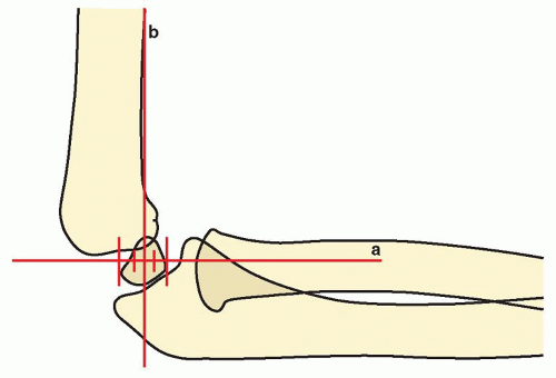
Fig. 6.11). Rogers has pointed out, in addition, the importance of the position of the capitellum relative to the distal humerus and the proximal radius. He found that a line drawn along the longitudinal axis of the proximal radius passes through the center of the capitellum and that a line drawn along the anterior cortex of the distal humerus and extended downward through the articulation intersects the middle third of the capitellum (
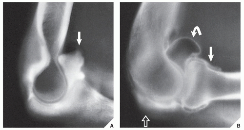
Fig. 6.12). A disruption of this relation serves as an important indication of the possible presence of a fracture or dislocation. Finally, regardless of the patient’s age, a displacement of the normal positions of the fat pads of the elbow also provides a useful diagnostic clue to


the presence of a fracture. Normally, the posterior fat pad, which lies deep in the olecranon fossa, is not visible on the lateral view. When it becomes visible and the anterior fat pad appears displaced—the positive fat-pad sign (Fig. 6.13; see also Figs. 6.27B and 6.32A)—demonstration of the fracture line should be undertaken.
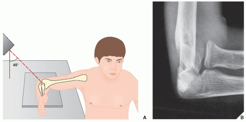


FIGURE 6.1 Osseous structures of the elbow. Anterior and posterior views of the distal humerus and the proximal radius and ulna.


FIGURE 6.2 Muscles of the elbow. Anterior and posterior views of the muscles of the elbow joint.


FIGURE 6.3 Ligaments of the elbow. Medial and lateral views of the ligaments of the elbow joint.


FIGURE 6.4 Anteroposterior view. (A) For the anteroposterior view of the elbow, the forearm is positioned supine (palm up) on the radiographic table, with the elbow joint fully extended and the fingers slightly flexed. The central beam is directed perpendicularly toward the elbow joint. (B) The radiograph obtained in this projection demonstrates the medial and the lateral epicondyles, the olecranon fossa, the capitellum, and the radial head. The coronoid process is seen en face, and the olecranon overlaps the trochlea.


FIGURE 6.5 Carrying angle. The angle formed by the longitudinal axes of the distal humerus and the proximal ulna constitutes the carrying angle of the forearm. Normally, there is a valgus angle of 15 degrees.


FIGURE 6.6 Ossification centers of the distal humerus. The secondary centers of ossification of the distal humerus usually appear in the following order: the capitellum at 1 to 2 years of age, the medial epicondyle at 4 to 5 years of age, the trochlea at 7 to 8 years of age, and the lateral epicondyle at 10 to 11 years of age.


FIGURE 6.7 Fracture of the medial epicondyle. Displacement of the ossification center of the medial epicondyle secondary to fracture (A) and (B) may mimic the normal appearance of the ossification center of the trochlea (C). The orange areas represent unossified cartilage which is not visualized on the radiographs.


FIGURE 6.8 CRITOE—The order and age of appearance of ossification centers around the elbow joint. C, capitellum (1 year); R, radius (3 years); I, internal (medial) epicondyle (5 years); T, trochlea (7 years); O, olecranon (9 years); E, external (lateral epicondyle (11 years).


FIGURE 6.9 Anteroposterior radiographs of the elbow in a child. (A) 2.5-year-old boy. Only ossification center for the capitellum is present. (B) 6.5-year-old girl. Three centers of ossification are present: for the capitellum, for the radial head, and for the medial (internal) epicondyle of the humerus.


FIGURE 6.10 Lateral view. (A) For the lateral projection of the elbow, the forearm rests on its ulnar side on the radiographic cassette, with the joint flexed 90 degrees, the thumb pointing upward, and the fingers slightly flexed. The central beam is directed vertically toward the radial head. (B) The radiograph obtained in this projection demonstrates the distal shaft of the humerus, the supracondylar ridge, the olecranon process, and the anterior aspect of the radial head. The articular surface and posterior aspect of the radial head are not well demonstrated on this view because of overlap by the coronoid process. The capitellum is also obscured by the overlapping trochlea.

The radial head-capitellum view is a variant of the lateral projection, which was introduced by Greenspan in 1982. As it overcomes the major limitation of the standard lateral view by projecting the radial head ventrad, free of overlap by the coronoid process, it has proved to be a particularly effective technique. In addition to the radial head, it also clearly demonstrates the capitellum, the coronoid process, the humeroradial and humeroulnar articulations (Fig. 6.14), and subtle fractures of these structures that may be obscure on other projections (see Figs. 6.29, 6.30, and 6.36).

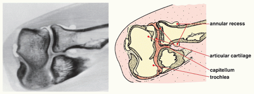
Other modalities may also be necessary for sufficient evaluation of an injury to the elbow. Single-contrast or, preferably, double-contrast arthrography, combined (in the past) with tomography (
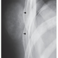
arthrotomography) and presently with computed tomography (CT), has proved effective in visualizing subtle chondral fractures, osteochondritis dissecans, synovial and capsular abnormalities, and osteochondral bodies in the joint. In general, indications for elbow arthrography include detection of the presence, size, and number of intraarticular osteochondral bodies; determination of whether calcifications around the elbow joint are intraarticular or extraarticular; evaluation of the articular cartilage; evaluation of juxtaarticular cysts if they are communicating with the joint; evaluation of the joint capacity; and evaluation of various synovial and capsular abnormalities. Singlecontrast arthrography is preferable when evaluating synovial abnormalities and intraarticular osteochondral bodies because double contrast may result in air bubbles in the joint. Double-contrast arthrography, however, provides more detailed information; in particular, the articular surface and synovial lining are better delineated and the small details can be better visualized (Fig. 6.15). In the past, in conjunction with elbow arthrography, conventional tomography was used in a procedure called arthrotomography (Fig. 6.16); however, currently it has been substituted by CT examination (CT-arthrography) (Fig. 6.17).

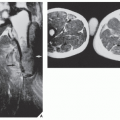
Axial CT images of the extended elbow are occasionally effective in demonstrating traumatic abnormalities. They are, however, difficult to obtain in the traumatized patient, and except for the visualization of the proximal radioulnar joint and ulnatrochlear articulation, they are not frequently used. Occasionally, these sections can demonstrate osteochondral fractures of the radial head and assess the integrity of the proximal radioulnar joint. However, Franklin and colleagues noted that axial CT images of the flexed elbow (so-called coronal sections) provide an ideal plane for the evaluation of the olecranon fossa and the space between the trochlea and the olecranon process posteriorly, as well as the radius and the capitellum, and the trochlea and the coronoid process anteriorly. Axial scans through the flexed elbow also allow additional demonstration of the proximal radius in its long axis.

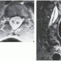
Magnetic resonance imaging (MRI) examination effectively demonstrates traumatic abnormalities of the elbow joint and surrounding soft tissues. Axial, sagittal, and coronal planes are routinely used for elbow imaging. The axial plane is ideal to display the anatomic relationship of the proximal radioulnar joint and the head of the radius. Various tendons, muscles, annular ligament, and neurovascular bundles are also effectively imaged. On coronal images, the trochlea, capitellum, and radial head are well demonstrated, as well as the various tendons, ligaments, and muscles around the elbow (Fig. 6.18A). On the sagittal images, the ulnatrochlear and radiocapitellar articulations are well seen, and the biceps, triceps, and brachialis muscle groups are well demonstrated in their long axis. The biceps tendon and anconeus muscles are also well imaged (Fig. 6.18B,C).

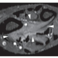
MR arthrography (MRa) is occasionally performed, mainly to evaluate synovial abnormalities and integrity of the joint capsule and ligaments. In addition, subtle intraarticular loose bodies can be detected with this technique, and the stability of osteochondral fracture or osteochondritis dissecans of the capitellum can be assessed. Similar to one used for shoulder MRa, a concentration of gadolinium mixed with normal saline, iodinated contrast agent, and lidocaine is prepared and a total of up to 10 mL of fluid is injected into the elbow joint. Lateral approach, identical to the technique for conventional elbow arthrography (see Fig. 6.16), is preferred. Coronal, sagittal, and axial images are obtained using fat-suppressed spin echo sequences (Fig. 6.19). During the evaluation of MRI of the elbow, it is helpful to use a checklist as provided in Table 6.1.

For a summary of the preceding discussion in tabular form, see Tables 6.2 and 6.3 and Figure 6.20.


Injury to the Elbow


Fractures About the Elbow


Fractures of the Distal Humerus

Because the nomenclature of the various structures of the distal humerus used in different anatomy and surgery textbooks is not uniform, confusion has arisen regarding the classification of fractures of the distal humerus. To clarify the picture, a simplified anatomic division of the distal humerus is shown in Figure 6.21. The significance of the distinction between the articular and the extraarticular parts of the distal humerus lies in its importance to diagnosis, treatment, and prognosis. For example, as Rockwood and Green contended, a fracture involving only the articular portion of the distal humerus usually results in a loss of motion, but not a loss of stability, whereas a fracture of an entire condyle—that is, both articular and extraarticular portions—usually leads to restriction of motion and instability.


FIGURE 6.11 Supracondylar fracture. (A) Lateral radiograph of the elbow joint in a 3-year-old child shows the normal hockey-stick appearance of the distal humerus. (B) Loss of this configuration, as seen in this radiograph of a 3.5-year-old girl who sustained trauma to the elbow 4 weeks before this examination, and (C) of a 4-year-old boy with an acute supracondylar fracture, serves as an important landmark in recognizing supracondylar fracture of the distal humerus. Note also that the anterior humeral line falls anterior to the capitellum, indicating an extension injury (see Fig. 6.12).


FIGURE 6.12 Landmarks of the elbow joint. In children, the normal position of the capitellum relative to the distal humerus and the proximal radius is determined by the portions of the capitellum intersected by two lines: Line (a) coincident with the longitudinal axis of the proximal radius passes through the center of the capitellum, and line (b) parallel to the anterior cortex of the distal humerus intersects the middle third of the capitellum. Disruption of this relation indicates the possible presence of an abnormality (see Figs. 6.11 B,C and 6.27B).


FIGURE 6.13 Fat-pad sign. Lateral radiograph of the elbow joint shows positive anterior (arrow) and posterior (curved arrow) fat-pad sign. Open arrow points to the subtle fracture of the radial head.


FIGURE 6.14 Radial head-capitellum view. (A) For the radial head-capitellum projection of the elbow, the patient is seated at the side of the radiographic table, with the forearm resting on its ulnar side, the elbow joint flexed 90 degrees and the thumb pointing upward. The central beam is directed toward the radial head at a 45-degree angle to the forearm. (B) The radiograph obtained in this projection shows the radial head projected ventrad, free of overlap by the coronoid process, which is also well demonstrated. This projection is also effective in evaluating the capitellum and the humeroradial and humeroulnar articulations.


FIGURE 6.15 Arthrography of the elbow joint. (A) For arthrographic examination of the elbow, the patient’s forearm is positioned prone on the radiographic table, with the joint flexed 90 degrees and the fingers lying flat. The joint is entered from the lateral aspect between the radial head and the capitellum, and under fluoroscopic control, 2 mL of positive contrast agent (60% diatrizoate meglumine) and 8 to 10 mL of room air are injected into the radiocapitellar joint. (The red dot marks the point of needle entrance.) Conventional radiographs or tomograms may then be obtained in the standard projections (see Figs. 6.16 and 6.44). (B,C) On the elbow arthrogram, one can distinguish anterior, posterior, and annular recesses of the joint capsule. The articular cartilage of the radial head and capitellum is also well demonstrated.


FIGURE 6.16 Arthrotomography of the elbow joint. A trispiral section through the ulnar-trochlear articulation (A) demonstrates the coronoid recess (arrow) and through the radiocapitellar articulation (B) demonstrates the annular (periradial) (arrow), anterior (curved arrow), and posterior (open arrow) recesses of the joint capsule.


FIGURE 6.17 CT-arthrography of the elbow. Postarthrography coronal CT scan of the elbow joint clearly demonstrates the annular recess and the outline of the lateral extension of the joint capsule. The articular cartilage is also well demonstrated.


FIGURE 6.18 Normal MRI anatomy of the elbow joint. On the coronal section (A), note the anatomic relationship of bony, muscular, and tendinous structures. On the sagittal sections (B,C) the muscular structures (brachialis muscle, anconeus muscle), tendons (triceps tendon, biceps tendon), and bones (distal humerus, olecranon process, and radial head) are well demonstrated.


FIGURE 6.19 MRa of the elbow. (A) Coronal T1-weighted fat-suppressed image shows the anterior band of the UCL (arrow) and the radial collateral ligament (curved arrow). The joint is outlined by a bright contrast agent. C, capitellum; T, trochlea; RH, radial head. (B) Sagittal T1-weighted fat-suppressed image obtained through the medial part of the elbow joint shows anterior (arrow) and posterior (open arrow) recesses. T, trochlea; O, olecranon; BM, brachialis muscle; TM, triceps muscle. (C) Sagittal T1-weighted fat-suppressed image obtained through the lateral part of the elbow joint shows attachment of the joint capsule to the proximal radius (arrow) and its posterior extent (open arrows). C, capitellum; RH, radial head.


TABLE 6.1 Checklist for Evaluation of Magnetic Resonance Imaging and Magnetic Resonance Arthrography of the Elbow


Osseous Structures


Medial epicondyle of the humerus (c, s, a)


Lateral epicondyle of the humerus (c, s, a)


Trochlea (c, s)


Capitellum (c, s)


Radial head (c, s)


Radial neck (c, s)


Coronoid process (s)


Olecranon (s)


Cartilaginous Structures


Articular cartilage (c, s, a)


Joints


Radiocapitellar (c, s)


Ulnatrochlear (c, s)


Proximal radioulnar (c, s, a)


Muscles and Their Tendons


Biceps (s, a)


Triceps (s, a)


Anconeus (s, a)


Brachioradialis (c, s, a)


Extensor carpi radialis—brevis, longus (c, a)


Muscles and Their Tendons (continued)


Extensor carpi ulnaris (c, a)


Extensor digitorum (c, a)


Flexor carpi ulnaris (c, a)


Flexor carpi radialis (c, a)


Flexor digitorum—superficialis, profundus (c, a)


Pronator teres (c, a)


Supinator (c, a)


Conjoined extensor-supinator tendon (c, a)


Palmaris longus (a)


Ligaments


Ulnar (medial) collateral—anterior, posterior, transverse (c)


Radial (lateral) collateral, including annular (a, c)


Bursae


Bicipitoradial (a)


Interosseous (a)


Other Structures


Ulnar nerve (a)


Median nerve (a)


Radial nerve (a)


The best imaging planes for visualization of listed structures are given in parenthesis. c, coronal; s, sagittal; a, axial.


TABLE 6.2 Standard and Special Radiographic Projections for Evaluating Injury to the Elbow


Projection


Demonstration


Anteroposterior


Supracondylar, transcondylar, and intercondylar fractures of the distal humerus


Fractures of


Medial and lateral epicondyles


Lateral aspect of capitellum


Medial aspect of trochlea


Lateral aspect of radial head


Valgus and varus deformities


Secondary ossification centers of distal humerus


Lateral


Supracondylar fracture of the distal humerus


Fractures of


Anterior aspect of radial head


Olecranon process


Complex dislocations in elbow joint


Dislocation of radial head


Fat-pad sign


External oblique


Fractures of


Lateral epicondyle


Radial head


Internal oblique


Fractures of


Medial epicondyle


Coronoid process


Radial head-capitellum


Fractures of


Radial head


Capitellum


Coronoid process


Abnormalities of humeroradial and humeroulnar articulations


TABLE 6.3 Ancillary Imaging Techniques for Evaluating Injury to the Elbow


Technique


Demonstration


Tomography (presently replaced by CT)


Complex fractures about the elbow joint, particularly to assess the position of fragments in comminution


Healing process:


Nonunion


Secondary infection


Arthrography (single or double contrast)


Subtle abnormalities of articular cartilage


Capsular ruptures


Synovial abnormalities


Chondral and osteochondral fractures


Osteochondritis dissecans


Osteochondral bodies in joint


CT (alone or combined with double-contrast arthrography)


Same as for arthrography


MRI and MRa


Abnormalities of the ligaments,a tendons, muscles, and nerves


Capsular rupturesa


Joint effusion


Synovial cystsa


Hematomas


Subtle abnormalities of bones (e.g., bone contusion)


Osteochondritis dissecana


Epiphyseal fractures (in children)


a These abnormalities are best demonstrated on MRa. CT, computed tomography; MRI, magnetic resonance imaging; MRa, magnetic resonance arthrography.


FIGURE 6.20 Spectrum of radiologic imaging techniques for evaluating an injury to the elbow. The radiographic projections or radiologic techniques indicated throughout the diagram are only those that are the most effective in demonstrating the respective traumatic conditions. #Almost completely replaced by CT. AP, anteroposterior; Int, internal; Obl, oblique; Ext, external; RH, radial head; C, capitellum.


FIGURE 6.21 Anatomic structures of the distal humerus. A simplified anatomic division of the structures of the distal humerus.


FIGURE 6.22 Fractures of the distal humerus. Classification of fractures of the distal humerus on the basis of extraarticular and intraarticular extension. (Modified from Müller ME, Allgower M, Schneider R, Willenegger H. Manual of internal fixation, techniques recommended by the AO Group, 2nd ed. Berlin, Germany: Springer-Verlag; 1979.)

Based on the structure involved, fractures of the distal humerus can be classified as supracondylar, transcondylar, and intercondylar as well as fractures of the medial and the lateral epicondyles, the capitellum, and the trochlea. The Müller classification is recommended because it is a practical one based on a distinction between intraarticular and extraarticular fractures (Fig. 6.22). Usually, such injuries pose no diagnostic problems in adults and are readily evaluated on the anteroposterior and lateral projections of the elbow (Figs. 6.23 and 6.24). In the past, tomographic examination was usually performed to localize comminuted fragments. Currently, CT is the modality of choice for this purpose (Fig. 6.25).

In children, the diagnosis may be problematic because of the presence of the secondary centers of ossification and their variability. Nevertheless, the anteroposterior and lateral projections usually suffice to demonstrate the abnormality, although the fracture line is occasionally more difficult to evaluate on the anteroposterior than on the lateral view. In children between the ages of 3 and 10 years, supracondylar fracture is the most common type of elbow fracture. Extension injury, caused by a fall on the outstretched hand with the elbow hyperextended, is present in 95% of such cases, and characteristically, the distal fragment is posteriorly displaced (Fig. 6.26). In the flexion type of injury caused by a fall on the flexed elbow, which occurs in only 5% of cases of supracondylar fracture, the distal fragment is anteriorly and upwardly displaced. Identifying supracondylar fracture on the lateral projection is usually facilitated by recognition of the loss of the normal hockey-stick appearance of the distal humerus and displacement of the capitellum relative to the line of the anterior cortex of the humerus (see Figs. 6.11 and 6.12). A positive fat-pad sign is invariably present (Fig. 6.27).

Only gold members can continue reading. Log In or Register to continue

Stay updated, free articles. Join our Telegram channel

Jul 24, 2016 | Posted by in MUSCULOSKELETAL IMAGING | Comments Off on Upper Limb II: Elbow

Full access? Get Clinical Tree

Get Clinical Tree app for offline access