Upper Limb III: Distal Forearm, Wrist, and Hand


Upper Limb III: Distal Forearm, Wrist, and Hand


Distal Forearm

An injury to the distal forearm, caused predominantly (90% of cases) by a fall on the outstretched hand, is common throughout life but is most common in the elderly. The type of injury usually sustained is a fracture of the distal radius or ulna, the incidence of which substantially exceeds that of a dislocation in the distal radioulnar and radiocarpal articulations. Although history and physical examination usually provide important information regarding the type of injury, radiographs are indispensable in determining the exact site and extent; in several types of fractures, only adequate radiographic examination can lead to a correct diagnosis.


Anatomic-Radiologic Considerations

Radiographs obtained in the posteroanterior and lateral projections are usually sufficient to evaluate most injuries to the distal forearm (Figs. 7.1 and 7.2). On each of these views, it is important to appreciate the normal anatomic relations of the radius and the ulna for a complete evaluation of trauma.

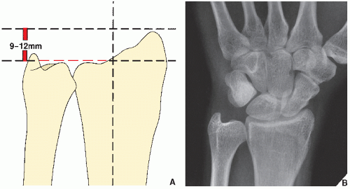
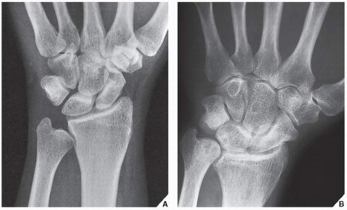
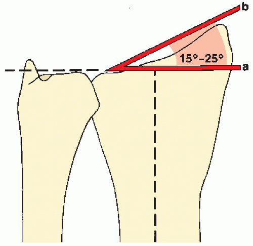
The posteroanterior view of the distal forearm reveals anatomic variations in the length of the radius and the ulna, known as ulnar variance or Hulten variance. As a rule, the radial styloid process exceeds the length of the articular end of the ulna by 9 to 12 mm. At the site of articulation with the lunate, however, the articular surfaces of the radius and the ulna are on the same level, yielding neutral ulnar variance (Fig. 7.3). Occasionally, the ulna projects more proximally—negative ulnar variance (or ulna minus variant)—or more distally—positive ulnar variance (or ulna plus variant) (Fig. 7.4). Wrist position is an important determinant of ulnar variance. The generally accepted standard position is a posteroanterior view obtained with the wrist flat on the radiographic table, neutral forearm rotation, and with the elbow flexed 90 degrees and the shoulder abducted 90 degrees. The posteroanterior radiograph also reveals an important anatomic feature of the radius known as the radial angle (also called the ulnar slant of the articular surface of the radius), which normally ranges from 15 to 25 degrees (Fig. 7.5).

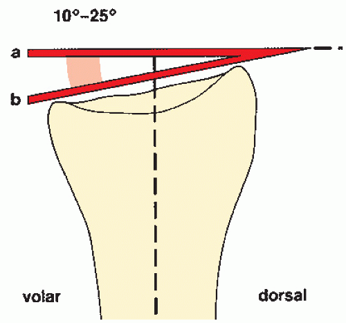
The lateral view of the distal forearm demonstrates another significant feature, the volar tilt of the articular surface of the radius (known variously as the dorsal angle, palmar facing, or palmar inclination). The tilt normally ranges from 10 to 25 degrees (Fig. 7.6).

Both these measurements have practical importance to the orthopedic surgeon in assessing the displacement and the position of fragments after a fracture of the distal radius. They can also help the surgeon to decide between closed and open reduction as well as assist in follow-up examinations.

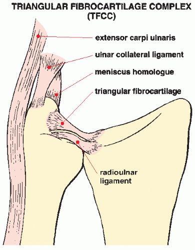
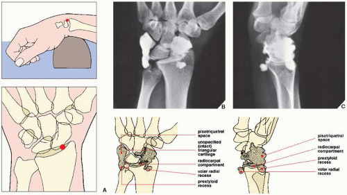
Ancillary imaging techniques are occasionally required for evaluating trauma to the distal forearm and wrist. Arthrographic examination (Fig. 7.7) may need to be performed in cases of suspected injury to the triangular fibrocartilage complex (TFCC), which consists of the triangular fibrocartilage (articular disk), the meniscus homolog, the dorsal and volar radioulnar ligaments, and the ulnar collateral ligament (Fig. 7.8). Because the radiocarpal cavity into which contrast is injected normally does not communicate with the distal radioulnar joint, opacification of this compartment indicates a tear of the triangular fibrocartilage (see Fig. 7.29). In a small percentage of cases, a false-positive result may be caused by a normal anatomic variant allowing communication between the radiocarpal compartment and the distal radioulnar joint.

For a summary in tabular form of the standard radiographic projections and ancillary imaging techniques used to evaluate trauma to the distal forearm, see Tables 7.1 and 7.2.


Injury to the Distal Forearm


Fractures of the Distal Radius

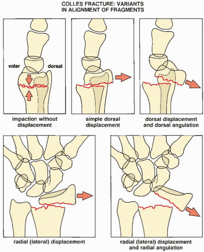
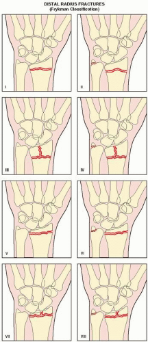
Colles Fracture. The most frequently encountered injury to the distal forearm, Colles fracture, usually results from a fall on the outstretched hand with the forearm pronated in dorsiflexion. It is most commonly seen in adults older than the age of 50 years and more often in women than in men. In the classic description of this injury, known in the European literature as the Pouteau fracture, the fracture line is extraarticular, usually occurring approximately 2 to 3 cm from the articular surface of the distal radius. In many cases, the distal fragment is radially and dorsally displaced and shows dorsal angulation, although other variants in the alignment of fragments may also be seen (Fig. 7.9). Commonly, there is an associated fracture of the ulnar styloid process. It should be noted that some authors (e.g., Frykman) include intraarticular extension of the fracture line, as well as an associated fracture of the distal end of the ulna, under this eponym (Fig. 7.10, Table 7.3).


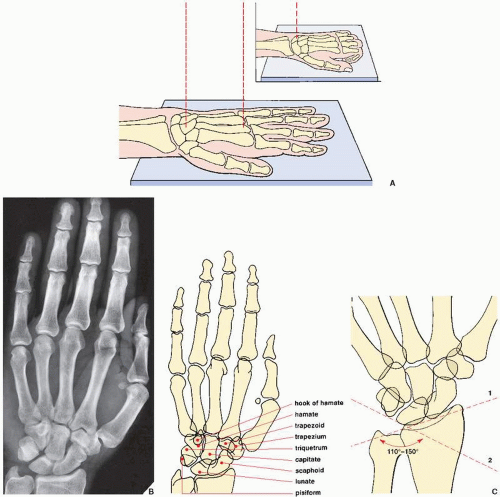
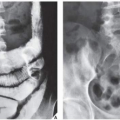
FIGURE 7.1 Dorsovolar (posteroanterior) view of the distal forearm, wrist, and hand. For the purpose of classification, a distinction is made between traumatic conditions involving the distal forearm, the wrist, and the hand. From a radiologic perspective, however, the positioning of the limb for posteroanterior and lateral films of the wrist area (i.e., the distal forearm and the carpus) and the hand is essentially the same. (A) For the posteroanterior (dorsovolar) view of the wrist and the hand, patients are seated with the arm fully extended on the radiographic table. The portion of the limb from the distal third of the forearm to the fingertips rests prone on the film cassette. Whether the wrist area or the hand is the focus of evaluation, the hand usually lies flat (palm down), with the fingers slightly spread. The point toward which the central beam is directed, however, varies. For the wrist, the beam is directed toward the center of the carpus; for the hand, the beam is directed toward the head of the third metacarpal bone. For better demonstration of the wrist area, the patient’s fingers may be flexed to cause the carpus to lie flat on the film cassette (inset). (B) On the radiograph obtained in this projection, the distal radius and the ulna, as well as the carpal and metacarpal bones and phalanges, are well demonstrated. The thumb, however, is seen in an oblique projection; the bases of the second to fifth metacarpals partially overlap. In the wrist, there is also overlap of the pisiform and the triquetrum, as well as the trapezium and trapezoid bones. (C) On this projection, a carpal angle can be determined. It is formed by two tangents, the first drawn against the proximal borders of the scaphoid and lunate (1) and the second drawn against the proximal borders of the triquetrum and lunate (2). The angle measures normally between 110 and 150 degrees, showing considerable deviation with age, sex, and race.


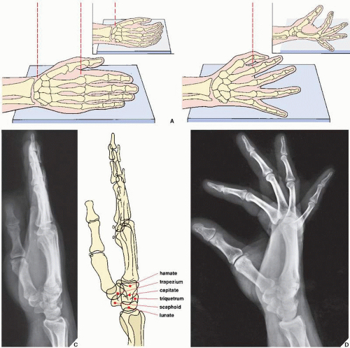
FIGURE 7.2 Lateral view of the wrist and hand. (A) For the lateral projection of the wrist area and the hand, the patient’s arm is fully extended and resting on its ulnar side. The fingers may be fully extended or, preferably, slightly flexed (inset), with the thumb slightly in front of the fingers. For the evaluation of the wrist area, the central beam is directed toward the center of the carpus, while for the hand, it is directed toward the head of the second metacarpal (B). On the radiograph obtained in this projection (C), the distal radius and the ulna overlap, but the relation of the longitudinal axes of the capitate, the lunate, and the radius can sufficiently be evaluated (see Fig. 7.80). Although the metacarpals and the phalanges also overlap, dorsal or volar displacement of a fracture of these bones can easily be detected (see Fig. 4.1). The thumb is imaged in true dorsovolar projection. A more effective way of imaging the fingers in the lateral projection is to have the patient spread the fingers in a fan-like manner, with the ulnar side of the fifth phalanx resting on the film cassette. The central beam is directed toward the heads of the metacarpals. (D) On the film in this projection, the overlap of the phalanges commonly seen on the standard lateral view is eliminated. The interphalangeal joints can readily be evaluated.


FIGURE 7.3 Neutral ulnar variance. (A) As a rule, the radial styloid process rises 9 to 12 mm above the articular surface of the distal ulna. This distance is also known as the radial length. (B) At the site of articulation with the lunate, the articular surfaces of the radius and the ulna are on the same level.


FIGURE 7.4 Negative and positive ulnar variance. (A) Negative ulnar variance. The articular surface of the ulna projects 5 mm proximal to the site of radiolunate articulation. (B) Positive ulnar variance. The articular surface of the ulna projects 8 mm distal to the site of radiolunate articulation.


FIGURE 7.5 Ulnar slant. The ulnar slant of the articular surface of the radius is determined, with the wrist in the neutral position, by the angle formed by two lines: one perpendicular to the long axis of the radius at the level of the radioulnar articular surface (a) and a tangent connecting the radial styloid process and the ulnar aspect of the radius (b).


FIGURE 7.6 Palmar inclination. The palmar inclination of the radial articular surface is determined by measuring the angle formed by a line perpendicular to the long axis of the radius at the level of the styloid process (a) and a tangent connecting the dorsal and volar aspects of the radial articular surface (b).


FIGURE 7.7 Arthrography of the wrist. (A) For arthrographic examination of the radiocarpal joint, the wrist is positioned prone on a radiolucent sponge to open the joint for needle insertion. Under fluoroscopic control, the joint is entered using a 22-gauge needle at a point lateral to the scapholunate ligament. (The red dot marks the site of puncture.) Two or three milliliters of contrast (60% diatrizoate meglumine) is injected, and posteroanterior (dorsovolar), lateral, and oblique films are obtained. Posteroanterior (B) and lateral (C) views show the contrast filling the radiocarpal compartment, the prestyloid and volar radial recesses, and the pisotriquetral space. Intact triangular fibrocartilage does not allow the contrast to enter the distal radioulnar joint, and intact intercarpal ligaments prevent a leak of contrast into the intercarpal articulations.


FIGURE 7.8 Triangular fibrocartilage complex. The TFCC includes the triangular fibrocartilage, radioulnar ligament, ulnocarpal ligament, extensor carpi ulnaris tendon and tendon sheath, and meniscus homolog. It is located between the distal ulna and the proximal carpal row, stabilizes the distal radioulnar joint, and functions as a cushion of compressing axial forces. The triangular fibrocartilage attaches medially to the fovea of the ulna and laterally to the lunate fossa of the radius.


TABLE 7.1 Standard Radiographic Projections for Evaluating Injury to the Distal Forearm


Projection


Demonstration


Posteroanterior


Ulnar variance


Carpal angle


Radial angle


Distal radioulnar joint


Colles fracture


Hutchinson fracture


Galeazzi fracture-dislocation


Lateral


Palmar facing of radius


Pronator quadratus fat stripe


Colles fracture


Smith fracture


Barton fracture


Galeazzi fracture-dislocation


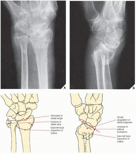
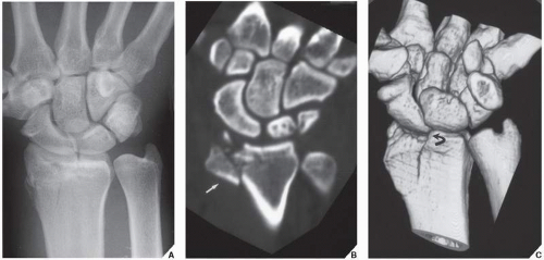
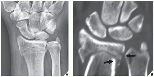
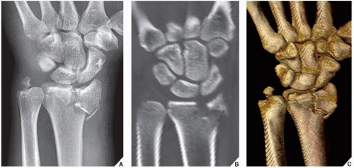
Radiographs in the posteroanterior and lateral projections are usually sufficient to demonstrate Colles fracture. The complete evaluation on both views should take note of the status of the radial angle and the palmar inclination as well as the degree of foreshortening of the radius secondary to impaction or bayonet-type displacement (Figs. 7.11 and 7.12). Computed tomography (CT) scanning may provide additional information concerning the exact position of displaced fragments (Figs. 7.13,7.14,7.15).

Complications. At the time of fracture, a concomitant injury to the median and ulnar nerves may occur. A lack of stability of the fragments during healing may result in a loss of reduction, but delayed union and nonunion are very rarely seen. As a sequela, posttraumatic arthritis may develop in the radiocarpal articulation.

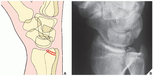
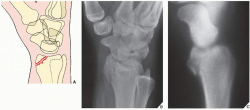
Barton and Hutchinson Fractures. Both these fractures are intraarticular fractures of the distal radius. The classic Barton fracture affects the dorsal margin of the distal radius and extends into the radiocarpal articulation (Fig. 7.16); occasionally, there may also be an associated dislocation in the joint. When the fracture involves the volar margin of the distal radius with an intraarticular extension, it is known as a reverse (or volar) Barton fracture (Fig. 7.17). Because in both variants the fracture line is oriented in the coronal plane, it is best demonstrated on the lateral or oblique projections.


TABLE 7.2 Ancillary Imaging Techniques for Evaluating Injury to the Distal Forearm


Technique


Demonstration


Arthrography


Radiocarpal articulation


Tear of TFCC


Arteriography


Concomitant injury to the arteries of the forearm


Radionuclide imaging (scintigraphy, bone scan) Computed tomography


Subtle fractures of the radius and the ulna


Depression, displacement, and spatial orientation of fracture fragments of the radius and the ulna


Fracture healing and complications of healing


Soft-tissue injury (muscles)


Magnetic resonance imaging and MR arthrography


Soft-tissue injury (muscles, tendons, ligaments)


Subtle fractures and bone contusion of the radius and the ulna


Tear of TFCC


Injury to the interosseous membrane


Abnormalities of various tendons, ligaments, and muscles


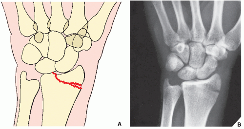
The Hutchinson fracture (also known as chauffeur’s fracture—a name derived from the era of hand-cranked automobiles when direct trauma to the radial side of the wrist was often sustained from recoil of the crank) involves the radial (lateral) margin of the distal radius, extending through the radial styloid process into the radiocarpal articulation. Because of the sagittal orientation of the fracture line, the posteroanterior view is better suited to diagnose this type of injury (Fig. 7.18).

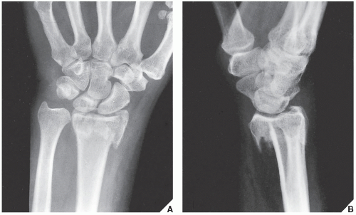
Smith Fracture. Usually resulting from a fall on the back of the hand or a direct blow to the dorsum of the hand in palmar flexion, a Smith fracture consists of a fracture of the distal radius, which sometimes extends into the radiocarpal joint, with volar displacement and angulation of the distal fragment (Fig. 7.19). Because the deformity in this fracture is the opposite of that seen in a Colles injury, it is often referred to as a reverse Colles fracture; it is, however, much less common than Colles. There are three types of Smith fracture, defined on the basis of the obliquity of the fracture line (Fig. 7.20), which is best assessed on the lateral projection. Types II and III are usually unstable and may require surgical intervention.

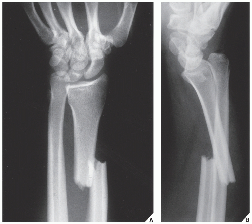
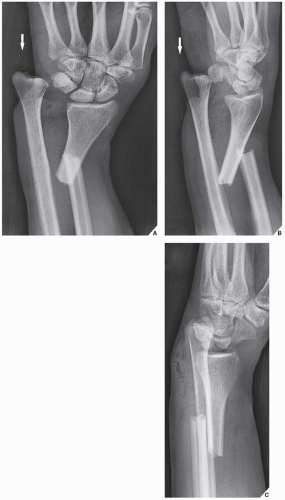
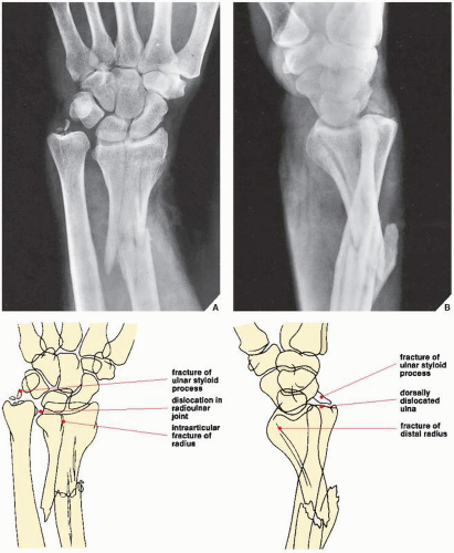
Galeazzi Fracture-Dislocation. This abnormality, which may result indirectly from a fall on the outstretched hand combined with marked pronation of the forearm or directly from a blow to the dorsolateral aspect of the wrist, consists of a fracture of the distal third of the radius, sometimes extending into the radiocarpal articulation and an associated dislocation in the distal radioulnar joint. Characteristically, the proximal end of the distal fragment is dorsally displaced, commonly with dorsal angulation at the fracture site; the ulna is dorsally and ulnarly (medially) dislocated (Fig. 7.21). On rare occasion, the distal fragment of the radius is volarly (anteriorly) displaced in relation to the proximal fragment and medially angulated (Fig. 7.22). Two types of Galeazzi injury have been identified. In type I, the fracture of the radius is extraarticular in the distal third of the bone (see Figs. 7.21 and 7.22). In type II, the radius fracture is usually comminuted and extends into the radiocarpal joint (Fig. 7.23).

Posteroanterior and lateral radiographs are routinely obtained when this injury is suspected, but the lateral view clearly reveals its nature and extent (see Figs. 7.21B, 7.22C, and 7.23B).


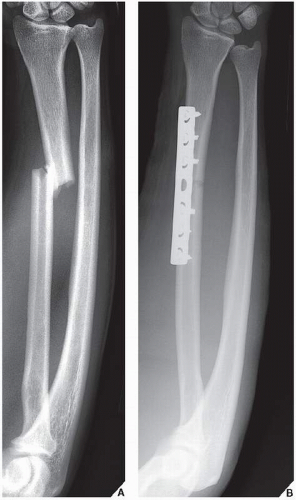
Piedmont Fracture. An isolated fracture of the radius at the junction of the middle and distal thirds without an associated disruption of the distal radioulnar joint is known as the Piedmont fracture (Fig. 7.24A). This injury is also called “fracture of necessity,” because open reduction and internal fixation are necessary to achieve an acceptable functional result (Fig. 7.24B). If this fracture is treated conservatively with closed reduction and cast application, then the interosseous space may be compromised because of muscle action, resulting in the loss of pronation and supination after the bone union is completed.

Essex-Lopresti Fracture-Dislocation. This fracture, which affects the radial head and is associated with a tear of the interosseous membrane of the forearm and dislocation in the distal radioulnar joint, was discussed in Chapter 6.


FIGURE 7.9 Colles fracture. Five variants of displacement and angulation of the distal fragment in Colles fracture. Some of these patterns may occur in combinations, yielding a complex deformity.

Ulnar Impingement Syndrome. Ulnar impingement syndrome is caused by a short distal ulna that impinges on the distal radius proximal to the sigmoid notch. A short ulna may represent a congenital anomaly, such as negative ulnar variance, or may be the result of premature fusion of the distal ulnar growth plate secondary to previous trauma. In most cases, however, it is caused by surgical procedures that involve a resection of the distal ulna secondary to trauma, rheumatoid arthritis, or correction of a Madelung deformity. The clinical symptoms of the ulnar impingement syndrome consist of ulnar-sided wrist pain and limitation of motion in the radiocarpal joint. In addition, patients experience discomfort during pronation and supination of the forearm. On radiography, the characteristic changes of this abnormality include a short ulna and scalloping of the medial aspect of the distal radius, in cases of negative ulnar variance (Fig. 7.25) or premature
fusion of the distal ulnar growth plate, or radial scalloping and radioulnar convergence, in cases of distal ulnar resection. Before these findings become obvious on conventional radiologic studies, magnetic resonance imaging (MRI) may be helpful in early recognition of this condition.


FIGURE 7.10 Distal radius fractures. Frykman classification of distal radius fractures according to the location of fracture line (intraarticular vs. extraarticular) and association of distal ulna fracture.


TABLE 7.3 Frykman Classification of Distal Radius Fractures


Radius Fracture


Distal Ulna Fracture


Location


Absent


Present


Extraarticular


I


II


Intraarticular (radiocarpal joint)


III


IV


Intraarticular (radioulnar joint)


V


VI


Intraarticular (radiocarpal and radioulnar joints)


VII


VIII


FIGURE 7.11 Colles fracture. Posteroanterior (A) and lateral (B) radiographs of the distal forearm demonstrate the features of Colles fracture. On the posteroanterior projection, a decrease in the radial angle and an associated fracture of the distal ulna are evident. The lateral view reveals the dorsal angulation of the distal radius as well as a reversal of the palmar inclination. On both views, the radius is foreshortened secondary to bayonet-type displacement. The fracture line does not extend to the joint (Frykman type II).

Ulnar Impaction Syndrome. Also known as the ulnolunate abutment syndrome or ulnocarpal loading, the ulnar impaction syndrome is a well-recognized entity clinically characterized by ulnar-sided wrist pain and limitation of motion in the radiocarpal joint. It is frequently associated with the positive ulnar variance. The pathologic mechanism of this syndrome is linked to altered and increased forces transmitted across the ulnar side of the wrist, leading to a compression of the distal
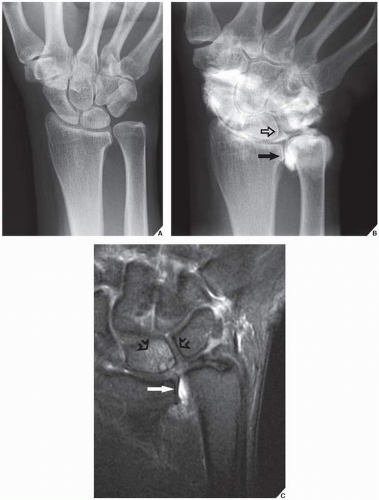
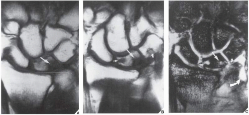
ulna on the medial surface of the lunate bone. This causes the development of degenerative changes in the cartilage covering both bones. In addition, frequent association of the tear of the triangular fibrocartilage has been reported. In cases of excessive ulnar length, dorsal subluxation of the ulna is present compromising supination of the forearm. The conventional radiography shows a positive ulnar variance associated with significantly decreased ulnolunate interval and occasionally foci of sclerosis or cystic changes in the lunate (Fig. 7.26). MRI is the most effective technique for the diagnosis of this syndrome and demonstration of pathologic changes in the affected bones and surrounding soft tissues. MRI reveals bone marrow edema of the distal ulna and lunate, subchondral sclerosis and cyst formation, and destruction of the cartilage. Associated abnormalities, such as tears of the triangular fibrocartilage and lunotriquetral ligament, are also well imaged (Figs. 7.27 and 7.28). Treatment of this condition includes TFCC debridement and ulnar shortening.
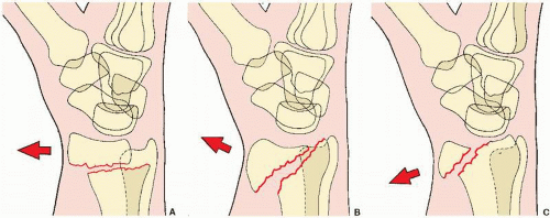


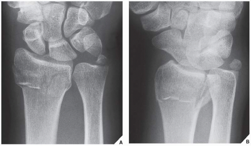
FIGURE 7.12 Intraarticular fracture of the distal radius. Posteroanterior (A) and oblique (B) radiographs of the distal forearm show Frykman type VI fracture. The fracture line extends into the distal radioulnar joint, and, in addition, there is a fracture of the ulnar styloid.


FIGURE 7.13 CT of an intraarticular fracture of the distal radius. (A) Posteroanterior radiograph of the wrist shows a fracture of the distal radius that appears to be nondisplaced. (B) Coronal reformatted and (C) 3D reconstructed CT images not only confirm the intraarticular extension of the fracture but also demonstrate displacement (arrow) and depression (curved arrow) of the fractured fragments. Because the distal radioulnar joint is spared and the ulna is intact, this injury represents Frykman type III fracture.


FIGURE 7.14 CT of an intraarticular fracture of the distal radius. (A) Posteroanterior radiograph of the wrist shows a fracture of the distal radius, but it is unclear if the fracture is extraarticular or intraarticular. In addition, there is a fracture of the styloid process of ulna. (B) Coronal reformatted CT image confirms that the fracture line extends into the distal radioulnar joint (arrows), but the radiocarpal joint is spared, thus rendering the diagnosis of Frykman type VI fracture.


FIGURE 7.15 CT of an intraarticular fracture of the distal radius. (A) Posteroanterior radiograph of the wrist shows an intraarticular fracture of the distal radius and a fracture of the ulnar styloid. (B) Coronal reformatted and (C) 3D reconstructed CT images clearly show an extension of the fracture lines into both the radiocarpal and the distal radioulnar joint compartments, confirming Frykman type VIII fracture.


FIGURE 7.16 Barton fracture. Schematic (A) and oblique radiograph (B) show the typical appearance of Barton fracture. The fracture line in the coronal plane extends from the dorsal margin of the distal radius into the radiocarpal articulation.


FIGURE 7.17 Reverse Barton fracture. Schematic (A), oblique radiograph (B), and lateral trispiral tomogram (C) show the reverse (or volar) Barton fracture; the fracture line is also oriented in the coronal plane but extends from the volar margin of the radial styloid process into the radiocarpal joint.


FIGURE 7.18 Hutchinson fracture. Schematic (A) and dorsovolar radiographs (B) showing classic appearance of Hutchinson fracture. The fracture line in the sagittal plane extends through the radial margin of the radial styloid process into the radiocarpal articulation.


FIGURE 7.19 Smith fracture. Posteroanterior (A) and lateral (B) radiographs of the distal forearm show the typical appearance of Smith fracture. Volar displacement of the distal fragment is clearly evident on the lateral view.


FIGURE 7.20 Smith fracture. The three types of Smith fracture are distinguished by the obliquity of the fracture line. Volar displacement of the distal fragment is characteristic of all three types. (A) In Smith type I, the fracture line is transverse, extending from the dorsal to the volar cortices of the radius. (B) The oblique fracture line in type II extends from the dorsal lip of the distal radius to the volar cortex. (C) Type III, which is almost identical to the reverse Barton fracture (see Fig. 7.17), is an intraarticular fracture with an extension to the volar cortex of the distal radius.


FIGURE 7.21 Galeazzi fracture-dislocation. Posteroanterior (A) and lateral (B) radiographs of the distal forearm show type I Galeazzi fracture-dislocation. The simple fracture of the radius affects the distal third of the bone, and the proximal end of the distal fragment is dorsally displaced and angulated. In addition, there is dislocation in the distal radioulnar joint.


FIGURE 7.22 Galeazzi fracture-dislocation. Posteroanterior (A), oblique (B), and lateral (C) radiographs of the distal forearm show a variant of type I injury, where the distal fragment of the radius is volarly displaced and medially angulated. Note that the distal ulna is protruding through the skin (arrow).


FIGURE 7.23 Galeazzi fracture-dislocation. Posteroanterior (A) and lateral (B) projections of the distal forearm demonstrate the two components of Galeazzi fracture-dislocation type II. The posteroanterior radiograph clearly reveals the fracture of the distal radius, which, in this case, is comminuted, extending into the radiocarpal joint. The distal fragment has a slight lateral angulation. Note also the associated comminuted fracture of the ulnar styloid process and the dislocation in the radioulnar joint. These features are also seen on the lateral projection, but this view provides in addition a better demonstration of the dorsal dislocation of the distal ulna.


FIGURE 7.24 Piedmont fracture. (A) Anteroposterior radiograph of the forearm shows a typical appearance of the Piedmont fracture, an isolated fracture at the junction of the middle and distal thirds of the radius, necessitating an open reduction and internal fixation (B).


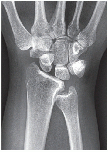
FIGURE 7.25 Ulnar impingement syndrome. Posteroanterior radiograph of the wrist shows a negative ulnar variance. The distal ulna impinges on the medial cortex of distal radius.


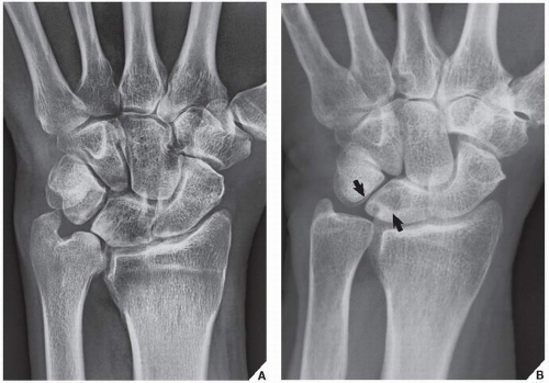
FIGURE 7.26 Ulnar impaction syndrome. (A) Posteroanterior radiograph of the wrist shows a positive ulnar variance. The ulnolunate interval is significantly decreased, and there is sclerosis of the distal ulna and medial aspect of the lunate. (B) In another patient, note the cystic changes in the lunate (arrows).


Injury to the Soft Tissue at the Distal Radioulnar Articulation

One of the most common sequelae of injury to the distal radioulnar articulation is a tear of the TFCC. A tear may occur as the result of fractures such as those described in the preceding sections or independently after an injury to the distal forearm and wrist.

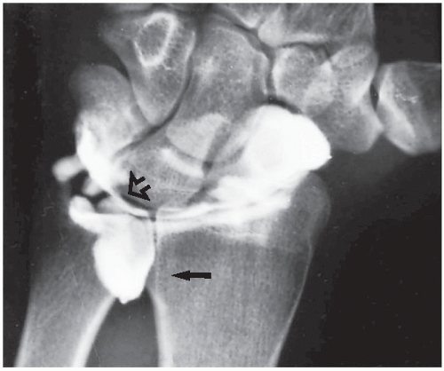
Radiographs in the standard projections are invariably normal regarding the status of the triangular cartilage, particularly if there is no evidence of fracture or dislocation on which to base a suspicion of soft-tissue injury. When it is suspected, however, a single-contrast arthrogram of the wrist can confirm or exclude the diagnosis. Normally, a contrast fills the radiocarpal compartment, the prestyloid and volar radial recesses, and the pisotriquetral space (see Fig. 7.7). The presence of a contrast in the distal radioulnar compartment or at the site of the triangular cartilage indicates a tear (Fig. 7.29).

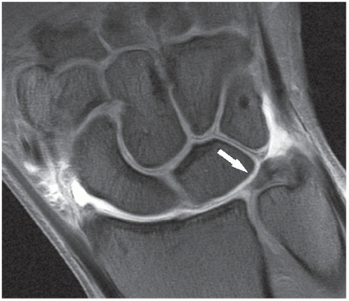
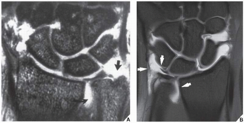
Until recently, arthrography has been the procedure of choice for the evaluation of TFCC. Currently, it is generally believed that in the diagnosis of TFCC abnormalities, particularly when using eight-channel phased-array extremity coil, MRI approaches and frequently surpasses arthrography in accuracy. The advantage of MRI is its noninvasiveness and ability to image the entire fibrocartilage substance, whereas arthrography is limited to the evaluation of the surface of this structure only. On coronal T1-weighted MR images, the normal TFCC appears as a biconcave band of homogeneous low signal intensity extending across the space between the distal ulna, the medial aspect of distal radius, and the triquetrum and lunate bones (Fig. 7.30, see also Fig. 7.8). Tears of the TFCC manifest as discontinuities and fragmentation of this structure. The torn fibrocartilage becomes irregular in contour and is interrupted by high signal intensity areas on T2-weighted images (Fig. 7.31). However, one of the studies published by Haims and colleagues, questions the sensitivity of MRI in diagnosing peripheral tears of the triangular fibrocartilage. In this respect, the authors reported the sensitivity of MRI of only 17%, with a specificity of 79%, and accuracy of 64%.


Wrist and Hand

Considered as a functional unit, the wrist and hand are the most common sites of injury in the skeletal system. Fractures of the metacarpals and phalanges, however, by far predominate in incidence over fractures and dislocations in the carpal bones and joints, which constitute approximately 6% of all such injuries. In most instances, history and physical examination provide valuable information on which to base a suspected diagnosis, but radiographic findings derived from films obtained in at least two projections at 90 degrees to each other (see Fig. 4.1) are essential to determine a specific diagnosis of injury to these sites.


FIGURE 7.27 Arthrography and MRI of the ulnar impaction syndrome. (A) Conventional radiograph of the wrist shows a positive ulnar variance, but there are no other appreciated abnormalities seen. (B) Wrist arthrogram shows a tear of the TFCC (arrow) and a tear of the lunotriquetral ligament (open arrow). (C) Coronal T2-weighted fat-suppressed MR arthrographic image shows contrast in the distal radioulnar joint (arrow), confirming the diagnosis of a tear of TFCC, and cystic changes and edema of the lunate (open arrows), confirming the diagnosis of ulnar impaction syndrome.


FIGURE 7.28 MRI of the ulnar impaction syndrome. (A) Coronal T1-weighted MR image shows a positive ulnar variance and sclerosis of the proximal ulnar aspect of the lunate (arrow). (B) Coronal T1-weighted MRI obtained slightly more volarly and (C) corresponding T2*-weighted image demonstrate subchondral cysts (straight arrows) and involvement of triquetrum (small curved arrows). Note also the disruption of the triangular fibrocartilage (large curved arrow).


FIGURE 7.29 Arthrography of a TFCC tear. A single-contrast arthrogram of the wrist shows a leak of contrast into the space occupied by the triangular cartilage (open arrow), with characteristic filling of the distal radioulnar compartment (arrow), confirming a tear of the TFCC (compare with Fig. 7.7B).


FIGURE 7.30 MRI of the wrist. Coronal T1-weighted fat-suppressed MR arthrographic image of the wrist shows a normal appearance of the TFCC (arrow).


FIGURE 7.31 MRI of the tear of the TFCC. (A) Coronal T2*-weighted GRASS image of the left wrist shows a full-thickness tear of the TFCC. The triangular fibrocartilage is torn and displaced from the ulnar styloid (arrow). Moderate amount of fluid is seen in the distal radioulnar joint (curved arrow). (B) In another patient, coronal proton density-weighted fat-suppressed arthrographic MR image of the wrist shows a tear of the TFCC (arrows).


Anatomic-Radiologic Considerations

Trauma to the wrist and hand usually can be sufficiently evaluated on conventional radiographs in the dorsovolar (posteroanterior) and lateral projections (see Figs. 7.1 and 7.2). However, the determination of the exact extent of damage to the different carpal bones forming the complex structure of the wrist may require supplemental studies specific for the various anatomic sites. These special views include the following:


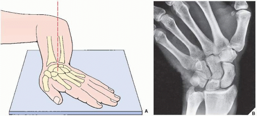
  • Dorsovolar obtained in ulnar deviation of the wrist for the evaluation of the scaphoid bone, which appears foreshortened on the standard dorsovolar projection as a result of its normal volar tilt (Fig. 7.32)


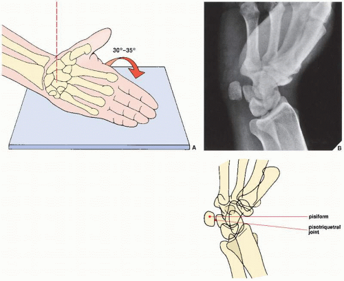
  • Supinated oblique for visualizing the pisiform bone and the pisotriquetral joint (Fig. 7.33)


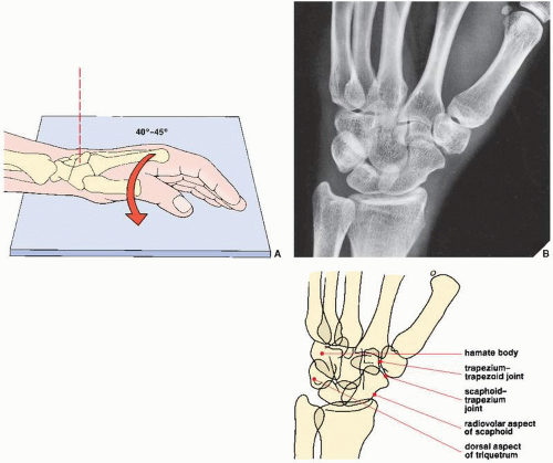
  • Pronated oblique for imaging the triquetral bone, the radiovolar aspect of the scaphoid, and the radial styloid process (Fig. 7.34)


  • Carpal tunnel for demonstrating the hook of the hamate, the pisiform, and the volar aspect of the trapezium (Fig. 7.35)


FIGURE 7.32 Ulnar deviation. (A) For the dorsovolar view of the wrist in ulnar deviation, the forearm rests flat on the radiographic table with the anterior surface down and the elbow flexed 90 degrees. The hand, lying flat on the film cassette, is ulnarly deviated. The central beam is directed toward the carpus. (B) The radiograph in this projection demonstrates the scaphoid free of the distortion because of its normal volar tilt when the wrist is in the neutral position.

A full assessment of traumatic conditions and their sequelae may also require ancillary imaging techniques. Among the most commonly performed in the past was conventional tomography, most often in the form of thin-section trispiral cuts for detecting occult fractures, currently almost completely replaced by CT. Fluoroscopy combined with videotaping is occasionally used for the evaluation of wrist kinematics and joint instability (see Fig. 7.85); arthrography, MRI, and magnetic resonance arthrography (MRa) are effective for determining soft-tissue injuries, such as tears of various ligaments, as well as capsular and tendinous ruptures; and radionuclide bone scan is very sensitive for
detecting subtle fractures and early complications of fracture healing. CT has evolved as a versatile tool and adjunctive procedure for imaging various traumatic abnormalities of the wrist. In many institutions, this technique virtually replaced conventional tomography, because it is easier to perform, is faster, and has a lower radiation dose. After standard axial sections are obtained, reformation images in additional imaging planes can be acquired and 3D reconstruction can be performed (see Fig. 2.8A,B). CT can be combined with arthrography (see Fig. 2.18) or can be enhanced by an intravenous contrast material. It is effective in demonstrating subluxation in the distal radioulnar joint and in evaluating the so-called humpback deformity of the scaphoid, osteonecrosis of the lunate (Kienböck disease), and fractures of the hook of the hamate, among other abnormalities. Axial sections are obtained after positioning the patient prone with the arm extended above the head. Contiguous sections of 1 or 2 mm are acquired, preferably using a spiral (helical) technique. Direct coronal sections can also be obtained with the wrist in maximal volar flexion or dorsal extension.


FIGURE 7.33 Supinated oblique view. (A) For the supinated oblique view of the wrist, the hand resting on its ulnar side on the film cassette is tilted approximately 30 to 35 degrees toward its dorsal surface. The outstretched fingers are held together, with the thumb slightly abducted. The central beam is directed toward the center of the wrist. (B) The radiograph in this projection demonstrates the pisiform bone and the pisotriquetral joint.

Arthrography still remains an effective procedure for evaluating the TFCC abnormalities and tears of various intercarpal ligaments. In general, single-contrast arthrography using a positive contrast agent is performed. However, if postarthrographic CT examination is to be performed, double-contrast arthrography using room air is preferable. The introduction of the three-compartment injection technique and combining the arthrographic wrist examination with digital technique and postarthrographic CT examination make this modality very effective in evaluating a painful wrist. A complete arthrographic evaluation of the wrist requires opacification of the midcarpal compartment, radiocarpal compartment, and distal radioulnar joint. These three compartments are normally separated from one another by various interosseous ligaments and, in the case of distal radioulnar joint, by the TFCC (Fig. 7.36). The flow of a contrast from one compartment to another indicates a defect in one of these ligaments. Unidirectional contrast flow through the ligament defects, associated with a small flap acting as a valve, has been reported and may be overlooked if the contrast is injected on only one side of the defect. For this reason, the separate injection of all three compartments is preferable. It has to be stressed, however, that defects in the ligaments may occasionally be found in normal, asymptomatic subjects; therefore, their significance remains uncertain.

More recently, digital subtraction arthrography has been advocated by Resnick and Manaster as an effective way to demonstrate subtle leaks of contrast. The advantages of digital subtraction arthrography include not only shortening of examination time but also a decrease in the concentration of contrast agent and more precise localization of defects in intercarpal ligaments, particularly when the defects are multiple (see Fig. 2.2).

At present, MRI is an imaging modality of choice for the evaluation of the wrist and hand (Fig. 7.37). To achieve optimum quality examination, the use of a dedicated local (surface) radiofrequency coil and limited field of view is recommended. This technique may image not only abnormalities of the soft tissues, including various muscles, tendons, interosseous ligaments, and triangular fibrocartilage, but also osseous abnormalities such as occult fractures and early osteonecrosis, particularly of the lunate and scaphoid. It is also very useful in imaging
the carpal tunnel (Fig. 7.38) and detecting the subtle abnormalities of carpal tunnel syndrome (Fig. 7.39). Commonly, MRI is performed after an intraarticular injection of a contrast agent (diluted gadolinium) into the radiocarpal compartment (see Fig. 7.30).
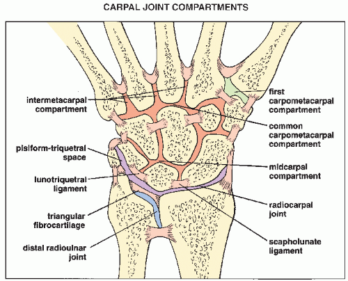


FIGURE 7.34 Pronated oblique view. (A) For the pronated oblique view of the wrist, the hand resting on its ulnar side on the film cassette is tilted approximately 40 to 45 degrees toward its palmar surface. The slightly flexed fingers are held together, with the thumb in front of them. The central beam is directed toward the center of the carpus. (B) The radiograph in this projection demonstrates the dorsal aspect of the triquetrum, the body of the hamate, the radiovolar aspect of the scaphoid, and the scaphoid-trapezium and trapezium-trapezoid articulations.


FIGURE 7.35 Carpal tunnel view. (A) For the carpal tunnel view of the wrist, the hand is maximally dorsiflexed by means of the patient’s opposite hand or a strap, with the palmar surface of the wrist resting on the film cassette. The central beam is directed toward the cup of the palm at approximately an angle of 15 degrees. (B) The radiograph in this projection demonstrates an axial view of the hook of the hamate as well as the pisiform bone and the volar margin of the trapezium.


FIGURE 7.36 Compartments of the carpus. Carpal joint compartments are separated from one another by various interosseous ligaments.

The coronal plane is the best to demonstrate the interosseous ligaments of the proximal carpal row (scapholunate and lunotriquetral ligaments) and the TFCC. These structures exhibit a low-intensity signal on T1- and T2-weighted sequences (see Fig. 7.37). In this plane, various intrinsic and extrinsic dorsal and volar ligaments of the wrist (Fig. 7.40) are also seen. In the sagittal plane, all flexor and extensor tendons with their respective insertions are clearly depicted, as well as some of the ligaments including the radioscaphocapitate, radiolunotriquetral, and dorsal radiolunate (Fig. 7.41). In the axial plane, various ligaments and tendons are shown in cross sections; their anatomic relationship to the bone structures, arteries, and nerves can be evaluated effectively (Fig. 7.42). This plane is also ideal for imaging of the Guyon canal. This anatomic structure is located on the volar aspect of the wrist, medially to the carpal tunnel, between the pisiform bone and the hook of the hamate (Fig. 7.43). It is bounded by the flexor retinaculum from the dorsal aspect, hypothenar musculature from the medial aspect, and by fascia from the volar aspect. It contains the ulnar vein, ulnar artery, and ulnar nerve.

Only gold members can continue reading. Log In or Register to continue

Stay updated, free articles. Join our Telegram channel

Jul 24, 2016 | Posted by in MUSCULOSKELETAL IMAGING | Comments Off on Upper Limb III: Distal Forearm, Wrist, and Hand

Full access? Get Clinical Tree
Get Clinical Tree app for offline access