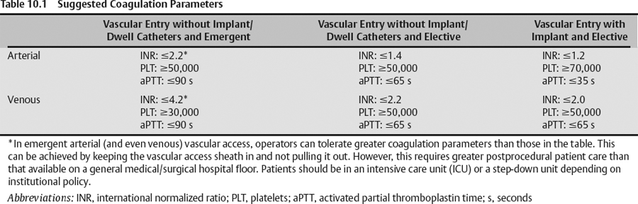
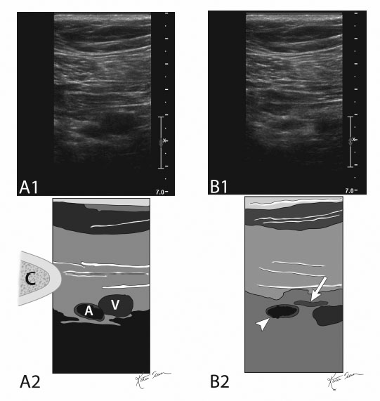
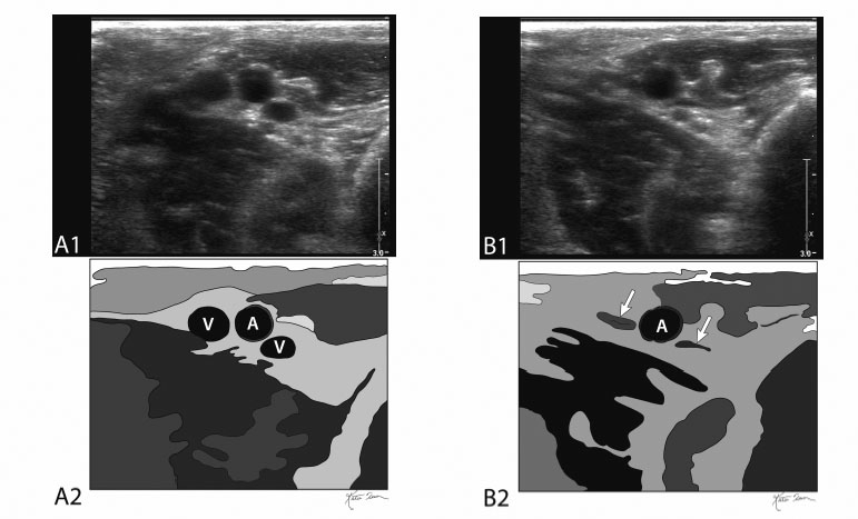
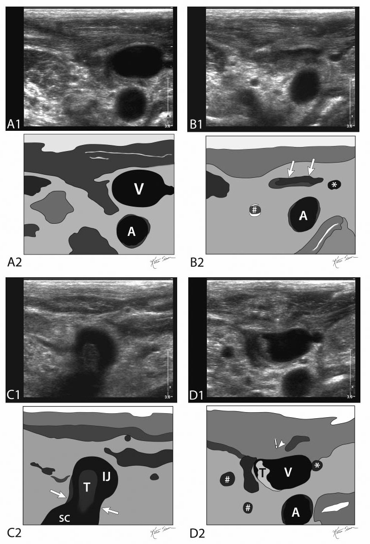
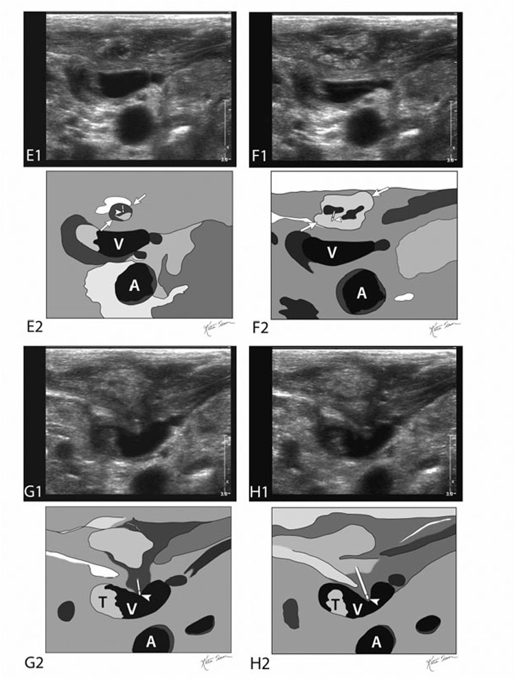
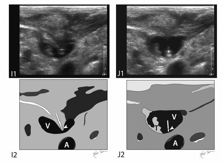
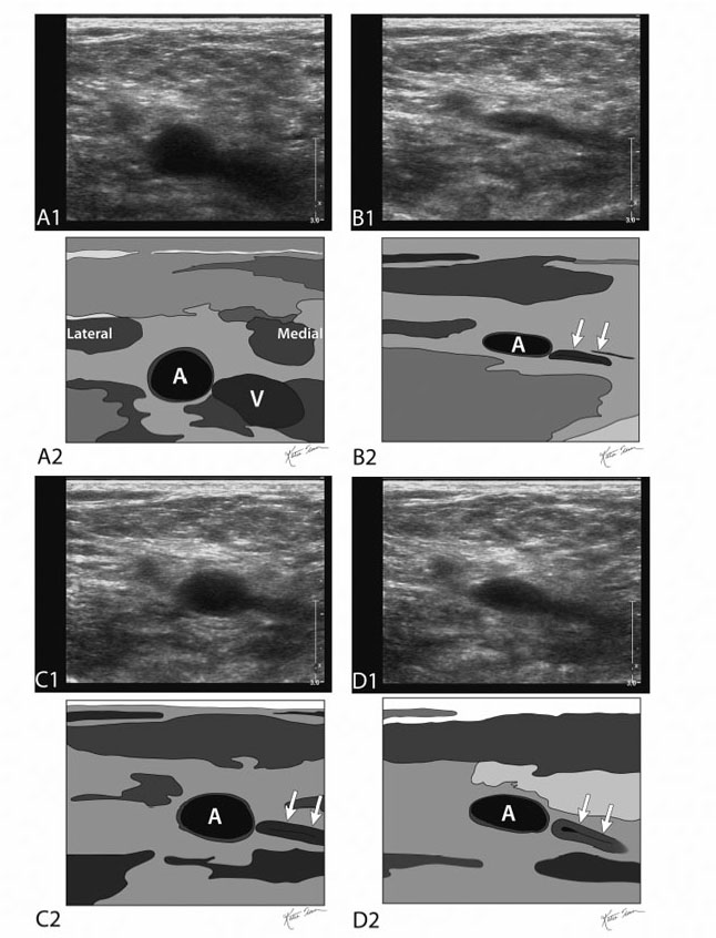
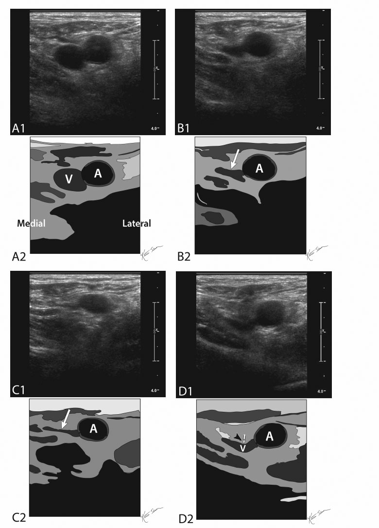
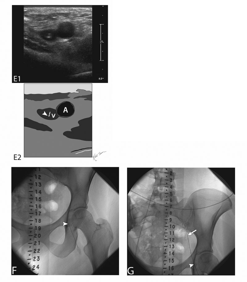
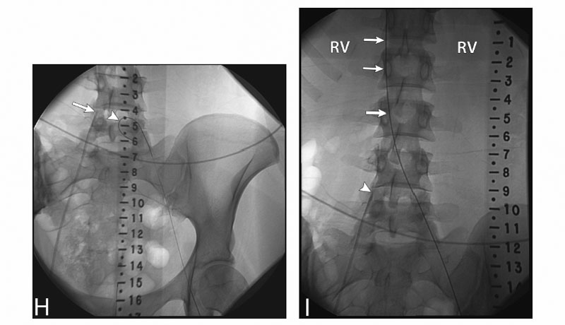
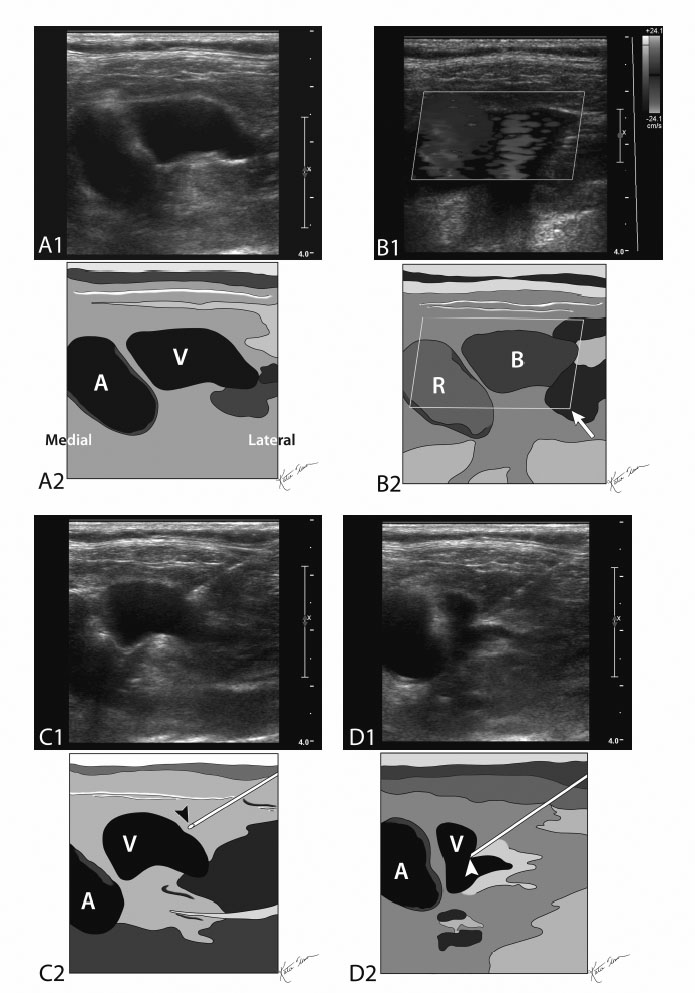
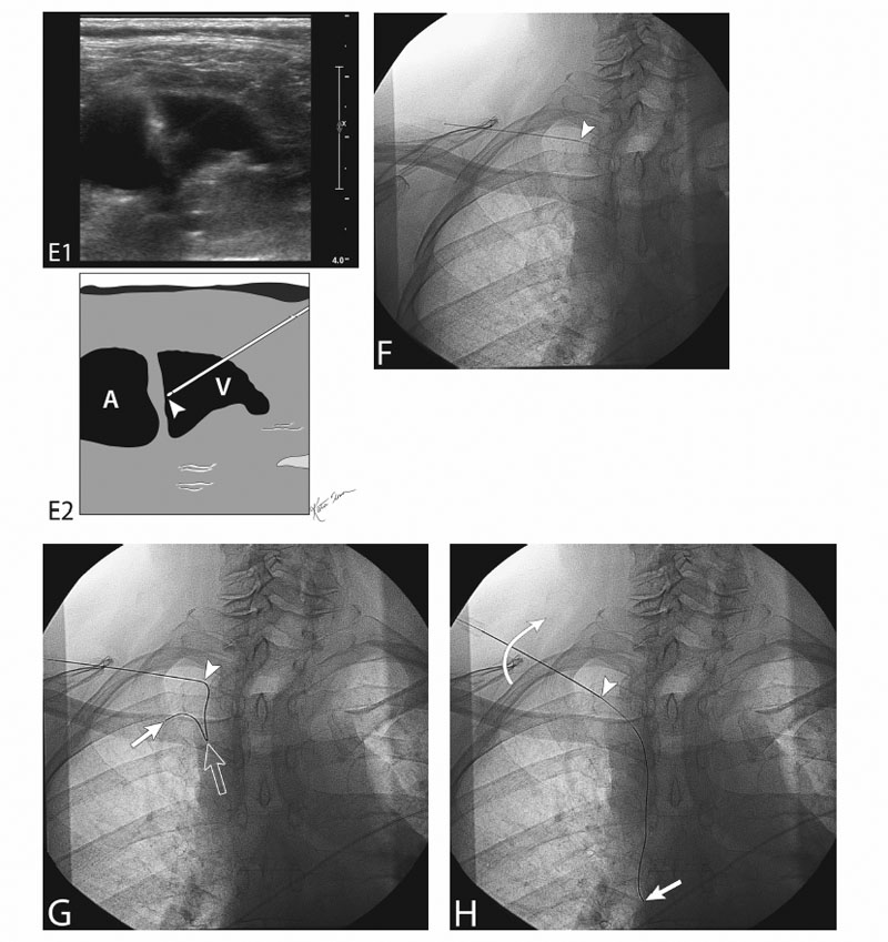
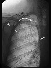
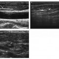
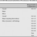
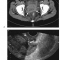
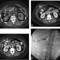
10 Vascular Access Vascular access is usually the “opening” step to myriad vascular procedures managing enumerable vascular and nonvascular diseases. Broadening this matter for discussion is the number of vessels, both arterial and venous, that can be used for access. Unfortunately, the scope of this book does not allow us to cover all of these procedures in detail. Indications, contraindications, and endpoints in this chapter are focused on vascular entry (access) only. Vascular access is usually the “opening” step to myriad vascular procedures managing enumerable vascular and nonvascular diseases. As a result, indications are broad. They depend on intent and vessel type. The following is a briefing. The intent of vascular access, in its simplest definition, is entry to the target vessel at a trajectory and in a particular vascular segment to be able to fulfill the greater aim of the procedure embarked on. Vascular access procedures can be classified into There are no true absolute contraindications. All contraindications are relative to the type and urgency of the procedure. In addition, the location and longevity of the access affect the coagulopathy threshold. Table 10.1 gives some idea about suggested coagulation parameters. There are no clear values set based on evidence-based research. These are suggested thresholds and personal opinion of the author. Evaluate prior cross-sectional imaging and laboratory values. Obtain informed consent and document a baseline vascular exam. All coagulation parameter thresholds are relative to the type and urgency of the procedure. In addition, the location and longevity of the access affect the coagulopathy threshold. Table 10.1 lists suggested coagulation parameters. There are no clear values based on evidence-based research. These are suggested thresholds based on my experience; they should aid in the decision-making process regarding implants versus no implants (dwell catheters) and the urgency of the procedure. Fig. 10.1 (A) Gray-scale ultrasound image (top) and schematic sketch (bottom) of the right subclavian vessels (A, subclavian artery; V, subclavian vein). This ultrasound image is obtained without compression (C, clavicle). (B) Gray-scale ultrasound image (top) and schematic sketch of it (bottom) of the right subclavian vessels while compressing down. As can be seen, the subclavian vein (arrow) is compressed and the subclavian artery is not completely compressed (arrowhead); it has a higher pressure that keeps it open. If more pressure is exerted (more than the systolic pressure of the subclavian artery) on the shoulder girdle, the artery will also compress completely. Fig. 10.2 (A) Gray-scale ultrasound image (top) and schematic sketch (bottom) of the brachial vessels (A, brachial artery; V, brachial veins). This ultrasound image is obtained without compression. (B) Gray-scale ultrasound image (top) and schematic sketch of it (bottom) of the brachial vessels while compressing down. As can be seen, the brachial veins (arrows) are compressed and the brachial artery (A) is not completely compressed; it has a higher pressure that keeps it open. If more pressure is exerted (more than the systolic pressure of the brachial artery) on the arm, the artery will also compress completely. Fig. 10.3 Ultrasound-guided jugular vein access. (A) Gray-scale ultrasound image (top) and schematic sketch (bottom) of a right jugular vein (V) and its adjacent carotid artery (A). This ultrasound image is obtained without compression. (B) Gray-scale ultrasound image (top) and schematic sketch (bottom) of a right jugular vein and its adjacent carotid artery (A) with compression using the linear ultrasound transducer. As can be seen, the jugular vein collapses (arrows) and the carotid artery is open. This helps the operator differentiate between vein and artery. Incidentally noted is a venous collateral (asterisk) and an external carotid artery branch (#). (C) Gray-scale ultrasound image (top) and schematic sketch (bottom) of a right internal jugular vein (IJ) to right subclavian vein junction (SC). The operator has paned down behind the clavicle to evaluate the distal internal jugular vein. This is where most internal jugular vein occlusions or stenoses occur. A nonocclusive thrombus (T) is seen in the jugulo-subclavian vein junction (between arrows). (D) Gray-scale ultrasound image (top) and schematic sketch (bottom) of a right jugular vein and its adjacent carotid artery (A). A lidocaine needle is seen approaching the jugular vein (arrowhead). Lidocaine has not yet been injected. Incidentally noted is a nonocclusive thrombus (T) in the jugular vein (V). Nonocclusive thrombus should not preclude jugular venous access. Also incidentally noted are venous collateral (asterisk) and external carotid artery arterial branches (#). (E) Gray-scale ultrasound image (top) and schematic sketch (bottom) of a right jugular vein (V) and its adjacent carotid artery (A). A lidocaine needle is seen near the jugular vein (arrowhead). Lidocaine is being injected and forming a wheal (between arrows). (F) Gray-scale ultrasound image (top) and schematic sketch (bottom) of a right jugular vein (V) and its adjacent carotid artery (A). The lidocaine needle tip is again seen near the jugular vein (arrowhead). Lidocaine continues to be injected and creates a larger wheal (between arrows). (G) Gray-scale ultrasound image (top) and schematic sketch (bottom) of the right jugular vein (V). A 21-gauge needle has been advanced by the operator and the needle tip is pushing down and indenting the superficial wall of the jugular vein (arrowhead at needle tip). Again noted is a nonocclusive thrombus in the jugular vein. The carotid artery (A) is deeper than the jugular vein. (H) Gray-scale ultrasound image (top) and schematic sketch (bottom) of the right jugular vein (V). The 21-gauge needle has been advanced further by the operator and the needle tip is still pushing down and indenting the superficial wall of the jugular vein (arrowhead at needle tip) and has not yet impaled the superficial wall. Again noted is a nonocclusive thrombus in the jugular vein (T). The carotid artery (A) is deeper than the jugular vein. (I) Gray-scale ultrasound image (top) and schematic sketch (bottom) of the right jugular vein (V). The 21-gauge needle has been advanced even further by the operator and the needle tip is still pushing down and indenting the superficial wall of the jugular vein (arrowhead at needle tip) and has not yet impaled the superficial wall. The needle tip (arrowhead) has been pushed almost down to the deep wall of the jugular vein. Again noted is a nonocclusive thrombus in the jugular vein. The carotid artery (A) is deeper than the jugular vein. (J) Gray-scale ultrasound image (top) and schematic sketch (bottom) of the right jugular vein (V). The 21-gauge needle has been advanced deeper by the operator into the lumen of the jugular vein. The superficial wall of the jugular vein (V) has rebounded to its normal/original position once it has been impaled by the 21-gauge needle (arrowhead at needle tip). The needle tip is inside the lumen adjacent to the deep wall of the jugular vein. At this time, the procedure is converted to a fluoroscopy. Again incidentally noted is the nonocclusive thrombus (T) in the jugular vein. Fig. 10.4 (A) Gray-scale ultrasound image (top) and schematic sketch (bottom) of the right femoral vessels (A, femoral artery – seen lateral; V, femoral vein – seen medial). This ultrasound image is obtained without compression. (B,C,D) Gray-scale ultrasound images (top) and schematic sketches (bottom) of the right femoral vessels while compressing down. The pressure exerted is higher than the diastolic pressure and lower than the systolic pressure. Figures 10.4B-10.4D are in series. As can be seen, the femoral vein is always compressed (arrows) and the femoral artery partly compresses depending on what stage in the cardiac cycle the image was obtained. Figure 10.4B was obtained during diastole, Fig. 10.4C was in systole, and Fig. 10.4D was in the end of systole (starting to collapse). The pressure exerted by the ultrasound probe is high to compress the vein at all times, and is high enough to compress the artery during diastole but not in systole. Fig. 10.5 (A) Gray-scale ultrasound image (top) and schematic sketch (bottom) of the left femoral vessels (A, femoral artery – seen lateral; V, femoral vein – seen medial). This ultrasound image is obtained without compression. (B,C) Grayscale ultrasound images (top) and schematic sketches (bottom) of the femoral vessels while compressing down. As can be seen, the femoral vein (arrow) is compressed and the adjacent femoral artery (A) is not completely compressed; it has a higher pressure that keeps it open. The operator has now identified/confirmed which vessel is a vein and which is an artery, and that the femoral vein is not thrombosed. Thrombosed veins do not compress. (C) The operator has exerted more pressure compared with (B). (D) Gray-scale ultrasound image (top) and schematic sketch (bottom) of the left femoral vessels (A, femoral artery; V, femoral vein). A 21-gauge needle has been advanced by the operator and is now tenting the superficial wall of the femoral vein (arrowhead at needle tip). (E) Gray-scale ultrasound image (top) and schematic sketch (bottom) of the left femoral vessels (A, femoral artery; V, femoral vein). A 21-gauge needle has been advanced by the operator into the femoral vein. The superficial wall of the femoral vein has rebounded to its normal/original position once it has been impaled by the 21-gauge needle (arrowhead at needle tip). At this time, the procedure is converted to a fluoroscopy. (F) Fluoroscopic image of the left hip and pelvis after the 21-gauge needle has been placed into the left femoral vein (arrowhead at needle tip). A radiopaque ruler is placed to aid in femoral access for an inferior vena cava filter placement. (G) Fluoroscopic image of the left hip and pelvis after the 21-gauge needle has been placed into the left femoral vein (arrowhead at needle tip). A 0.018-inch wire has been passed coaxially through the needle. The leading tip of the wire (arrow) is seen projecting in the vicinity of the left iliac vein. (H) Fluoroscopic image of the left hip and pelvis. The 0.018-inch wire has been advanced further and has curled in the specious left iliac vein (arrowhead). Incidentally noted is a right femoral vein central line (arrow at central catheter tip), which delineates the anatomy of the confluence of the common iliac veins. (I) Fluoroscopic image of the upper pelvis and lumbar spine. The 0.018-inch wire has been advanced further and is now in the inferior vena cava (IVC; arrows). Wires that go smoothly to the right side of the vertebral column are most likely venous (IVC is to the right of midline) and less likely arterial (aorta is to the left of midline). Again, incidentally noted is the right femoral vein central line (arrow at central catheter tip), which delineates the anatomy of the confluence of the common iliac veins. RV refers to the level of the renal veins. Fig. 10.6 (A) Gray-scale ultrasound image (top) and schematic sketch (bottom
Classification
Indications
Indications Based on Intent
Indications Based on Vessels: Venous
Indications Based on Vessels: Arterial
Contraindications
Preprocedural Evaluation
Indications
Alternatives
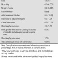
Procedural Risks
Equipment
Ultrasound Guidance
Standard Surgical Preparation and Draping
Local Infiltrative Analgesia Administration
Sharp Access
Coaxial Wires and Tubular Access
Tubular Access Devices
Technique
Intravenous Access and Medication
Preaccessment Ultrasound Exam
Related posts:
![]()
Stay updated, free articles. Join our Telegram channel

Full access? Get Clinical Tree


