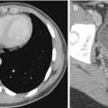
Fig. 14.1
Axial contrast-enhanced CT image shows that streak artifacts due to contrast material in the superior vena cava can mimic dissection of the ascending aorta
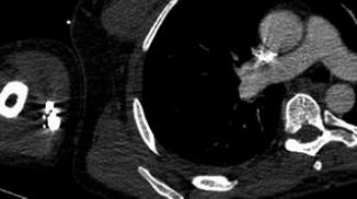
Fig. 14.2
Axial contrast-enhanced CT image shows that streak artifacts arising from contrast material in the arm vein have resulted in an artifact in the ascending aorta. This should not be mistaken for a dissection flap
Patient movement may result in misregistration artifacts. Again, this is of particular importance in imaging of the thoracic aorta and aortic root. Software corrections and cardiac gating (Fig. 14.3a, b) can be used to correct some of the involuntary movement artifacts that affect vascular imaging (Barrett and Keat 2004). Motion of the free wall of the left ventricle may also produce artifacts that project over the descending aorta. Reconstruction of CT images can also result in a number of potential pitfalls. These are related to thresholding range, explaining why the stenosed part of a tubular structure can be artificially narrowed with a high threshold and minimized with a low threshold. The presence of heavy calcification can significantly limit our ability to interpret multiplanar reconstructions of small peripheral vessels. Several periaortic structures such as origins of the arch vessels, left brachiocephalic, superior intercostal, and pulmonary veins may be interpreted as double lumina or intimal flaps (Fig. 14.4).
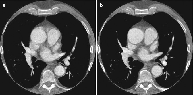
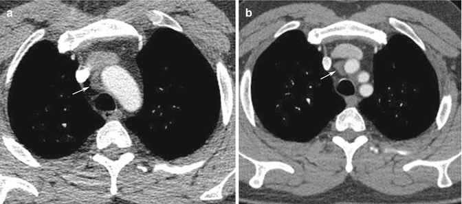
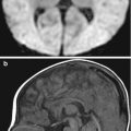
Fig. 14.3
(a) Non-gated axial contrast-enhanced CT image taken at aortic root level shows pulsation artifacts mimicking type 1 dissection. (b) ECG-gated axial contrast-enhanced CT image of the same patient confirms that there is no dissection flap
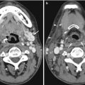
Fig. 14.4
Periaortic structures. (a) Ungated axial contrast-enhanced CT image shows an area of low attenuation around the aortic arch, suspicious of intramural hematoma (arrow). (b) Follow-up ECG-gated axial contrast-enhanced CT image shows the low-attenuation area to be clearly separated from the aorta. This appearance is caused by a high-riding superior pericardial recess (arrow)
14.2.2 Magnetic Resonance Imaging
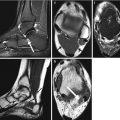
A common artifact that is seen on MR angiography (MRA) is the susceptibility artifact. This results from the presence of previously implanted metallic material (Fig. 14.5). Magnetic susceptibility effects on spins near a metal object distort the image either by loss of signal in the object or by distorting its spatial geometry (Lee et al. 2007). Stents, clips, prosthesis, and inferior vena cava (IVC) filters are some of the metallic devices that produce susceptibility artifacts. These often cause signal loss and influence our ability to comment, for instance, on the presence of in-stent stenosis or on other occasions produce apparent lesions, which are not confirmed during subsequent investigations. Catheters can mimic pseudo-filling defects and dissections, and artifacts caused by surgical clips can also mimic pseudo-stenoses or occlusions. In contrast-enhanced studies, timing of gadolinium injection contributes to pitfalls in image acquisition. Ringing artifacts and venous contamination are usually related to improper timing apart from suboptimal images for diagnosis (Lee et al. 2007). In vessels with turbulent flow, significant dephasing leads to signal dropout. While this effect can be reduced by the use of gadolinium-enhanced MRA, all MRI techniques are affected by this phenomenon. As a result, there is a tendency for MRI to overestimate the severity of vessel stenosis, and this affects all vascular territories to some extent.
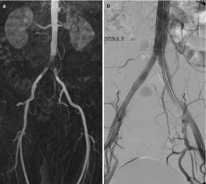
Fig. 14.5
(a) MRA in a patient with recurrent claudication shows apparent narrowing at the aortic bifurcation. (b) DSA shows that the previously implanted stents are patent and confirms that the MRA appearances are caused by susceptibility artifacts
14.2.3 Ultrasound Imaging
Errors that occur in evaluation of abnormalities on duplex imaging include those which are operator dependent, patient related, and inherent to all ultrasound imaging. Many of these examples are dealt with elsewhere in this textbook (see Chap. 1). With regard to the imaging of vascular structures, there are a certain number of pitfalls that merit specific attention. Patient-related factors include the inability to image certain vessels due to physical habitus and related organs. Examples of this include failure to image parts of the common iliac arteries due to their deep position and overlying bowel gas. Although the presence of more proximal disease can often be inferred from flow signal data, it is not always possible to demonstrate the causative lesions. Similarly, imaging of the mesenteric vessels may be difficult due to overlying bowel gas. High bifurcation of the carotid arteries can pose significant practical problems in duplex imaging. Acoustic shadowing from calcified plaques may impair detection and grading of stenoses, especially in small arteries such as the tibial vessels. Careful insonation of flow is vital in quantitative pulsed or continuous wave Doppler studies. Proper angulation of the ultrasound beam can be technically difficult, in spite of changing the probe angulation. An example of this is seen in the arched segment of the common iliac artery at its bifurcation. Aliasing might occur within arteries interrogated with a small Doppler angle, which could result in underestimation of peak flow velocity. An appreciation of the possible under- or overestimation of flow velocities is important, if operators are to avoid making errors. Appreciation of appropriate machine settings should help to avoid many potential problems, but careful attention with regard to gain settings is important in the measurement of vessel size.
14.2.4 Catheter Angiography
DSA has replaced cut-film angiography and currently remains as the gold standard for angiographic diagnosis. However, in common with other imaging techniques, it is subject to certain inherent limitations. Perhaps the most common problem in clinical practice relates to the occurrence of misregistration artifacts. These occur due to a failure of accurate superimposition of the mask image and subsequently imaged anatomic structures. They occur due to uncontrollable movement of organs such as bowel or heart or involuntary movements such as poor breath holding and swallowing during image acquisition. Re-masking (choosing an alternate image of the sequence as a mask) and pixel shifting (reregistering an image) are used to reduce the misregistration artifact (Fig. 14.6). Other patient-related factors such as the presence of foreign bodies, dental fillings, and prosthetic joints can adversely affect DSA imaging (Fig. 14.7). Improper catheter selection and engagement can significantly influence the ability to demonstrate branch vessel anatomy and lead to potentially significant lesions being overlooked. Proper selection of contrast strength, volume, and flow rate is also essential, if reliable diagnostic imaging is to be obtained. Careful timing of bolus injections is needed for delineation of vessels distal to long segments of vessel occlusion, an important example being the demonstration of crural vessels and foot arches.
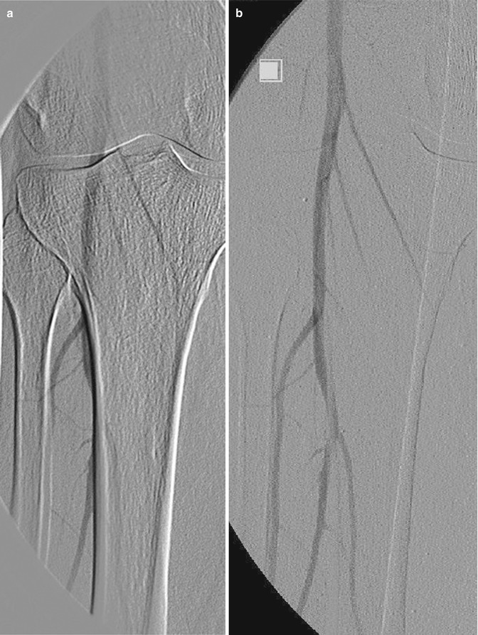
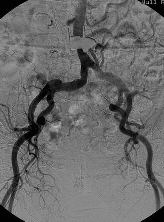
Fig. 14.6
DSA of the popliteal artery. (a) Misregistration artifact due to patient movement and (b) corrected by pixel shifting software
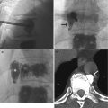
Fig. 14.7
DSA shows an apparent aortic lesion resulting from a metallic implant from previous spinal surgery
14.3 Pitfalls and Errors Related to Specific Vascular Territories
14.3.1 Carotid Arteries and Supra-aortic Branches
The carotid and vertebral arteries are routinely imaged for investigation and planning of intervention in stroke patients. Duplex evaluation of these vessels tends to be the initial preferred modality due to its noninvasive nature and wide availability. There are a number of common pitfalls which are encountered in duplex evaluation of the carotid and vertebral arteries. These include mistaking external carotid artery (ECA) stenosis for internal carotid artery (ICA) stenosis, calcification leading to acoustic masking, and underestimation of stenosis and overestimation of stenosis in the presence of contralateral occlusion. Mistaking the external and internal carotid arteries is especially important when a single patent vessel is seen beyond the bifurcation. The relative size and orientation of the vessels are often helpful but are by no means completely dependable. The most reliable factor in identifying the external carotid artery is the presence of branches in the neck. Rarely, anatomic variants of the internal carotid artery occur with vessel branching, but the pattern is distinct from that seen in the ECA. Another important means of differentiating the ECA and ICA is the use of the “temporal tap maneuver.” This is achieved by tapping over the region of the temporal artery to look for reflected flow waves (Kliewer et al. 1996). The technique is not however infallible, particularly in the rigid vessels of elderly patients where back transmission of the tapping wave can occur in the ICA.
Calcification may lead to underestimation of stenosis. Due to acoustic shadowing, large calcified plaques can result in non-visualization of lumen and prevent the inability to obtain adequate quantitative flow velocity measurements. Measurement of flow velocities measured beyond the area of calcification may lead to erroneous underestimation of stenosis. Overestimation of stenosis may occur in the presence of contralateral occlusion. An increase in peak systolic velocities of a patent ipsilateral internal carotid artery has been reported in the presence of contralateral internal carotid occlusion or severe stenosis. This should not be interpreted as a stenosis (Henderson et al. 2000). Preservation of a laminar flow waveform may be an important indicator that the increase in flow velocity may be physiological.
MRA of the carotid and vertebral arteries is being increasingly used to assess the carotid arteries, especially when coupled with imaging the brain in the clinical setting of stroke or transient ischemic attacks. MRA is now also the modality of choice in the evaluation of other conditions including thoracic outlet syndrome, arm claudication, and arteritis involving the supra-aortic vessels. In the interpretation of these studies, there are a number of important potential pitfalls. 3T susceptibility artifacts can attenuate intravascular signal and reduce the apparent caliber of the vessels. These artifacts typically occur at the carotid siphon exaggerating the degree of stenosis. Turbulent flow on MRI and MRA can produce a false-positive finding for dissection by producing hyperintense signal in the periphery of the arterial flow void along the surface of the arterial lumen. This signal can be mistaken for intramural hematoma. This problem can usually be alleviated by MRA (Provenzale et al. 2011).
CT angiography (CTA) is widely available and is used to evaluate the supra-aortic vessels. In this setting, it is commonly affected by artifacts especially related to motion, including swallowing and respiration. In addition, streak artifacts from injected contrast material in the axillary and subclavian veins are not infrequent. Pitfalls in CT of the carotid arteries include atherosclerosis being mistaken for hematoma, artifact from dental amalgam, contrast material extravasation mistaken for pseudoaneurysm, pulsation artifact, ulcerated plaque simulating intimal flap, and slow flow mimicking dissection. Admixture of non-opacified blood into the subclavian veins and superior vena cava can also cause diagnostic difficulty as it may mimic filling defects. CTA is not widely used to evaluate distal vessels of upper limbs because of poor opacification related to poor timing, especially in the presence of embolization or disruption secondary to trauma.
In modern radiological practice, catheter angiography is less commonly undertaken for assessment of the carotid vessels. Arch angiography is usually sufficient for demonstration of the carotid bifurcation. In cases where trickle flow is suspected within an internal carotid vessel, it is important that selective catheterization of the relevant common carotid vessel is performed, as otherwise, this important finding can be overlooked using a nonselective injection. Catheter angiography has a role to play in the evaluation of embolic pathologies to the extremities. It is important to perform selective angiography of the subclavian arteries, as arch angiography alone can result in underfilling of distal vessels, the visualization of which is crucial for planning embolectomy.
14.3.2 Thoracic Aorta
The thoracic aorta is commonly evaluated using a combination of radiographs, CT and MRI. Transthoracic and transesophageal echocardiography are now used less frequently in assessing the thoracic aorta but may be the first indication of significant aortic pathology. The radiographic finding of unfolding of the aging thoracic aorta is commonly misinterpreted as aortic dilatation. The presence of mural calcification can be very helpful in determining the true diameter of the aortic lumen. Due to errors in angulation of the ultrasound beam, false overestimation of the size of the aortic root may occur with transthoracic echocardiography. A horizontal orientation of the proximal ascending aorta is commonly seen in this situation.
The accurate recognition of thoracic aortic dissection is pivotal to good management and achieving a favorable prognosis but is affected by many factors that can lead to misinterpretation and misdiagnosis. Visualization of an intimomedial flap is central to the diagnosis of aortic dissection. This flap separates the true and false lumen, and delineation of its extent and characteristics are crucial to further management. Currently, this is usually achieved using contrast-enhanced computed tomography. Timing of the delivery of the contrast bolus is of critical importance to accurate assessment of thoracic aortic dissection. Excellent vascular enhancement is required to visualize the intimal flap and identify entry and exit points between the true and false channels. Triggering the acquisition either too early or too late can adversely affect the interpretation of findings. An example is that of the incorrect diagnosis of a thrombosed false lumen secondary to inadequate contrast enhancement (Chung et al. 1996).
Aortic wall motion during the cardiac cycle can produce curvilinear artifacts in the proximal ascending aorta and aortic root. These are usually observed in a small number of reconstructed axial slices and are seen at 12 or 1 o’clock position and 6 or 7 o’clock position. Electrocardiographic triggering can help reduce and resolve these artifacts (Fig. 14.3a, b). They can also be resolved with ultrafast electron beam CT (Duvernoy et al. 1995; Nakanishi et al. 1997). When these techniques are not available, careful review of the aortic root using multiplanar reconstructions and selective windowing of the images will often reveal the nature of such artifacts. Streak artifacts are a common problem while evaluating the aorta for dissection flaps. High-attenuation materials such as surgical staples, calcifications, pacemaker leads, high-contrast interfaces, and cardiac motion all contribute to streak artifacts (Fig. 14.2). These artifacts are seen in both non-enhanced and contrast-enhanced CT images and appear as parallel straight lines or radiate from a single point. They usually extend beyond the confines of the aortic lumen (Godwin et al. 1982; Gallagher and Dixon 1984; Demos et al. 1989). The presence of contrast material within the superior vena cava can also lead to confusing appearances within the ascending aorta (Fig. 14.1).
A number of periaortic structures can produce findings which may mimic aortic dissection. The origin of aortic arch branches, left brachiocephalic, and pulmonary veins can contribute to such appearances. These artifacts can usually be confirmed by scrolling through contiguous images and by reviewing multiplanar reconstructions. Anatomic variants such as the superior pericardial recess, residual thymus, or atelectasis can also be misinterpreted as dissection. Periaortic soft tissue masses can pose a considerable diagnostic challenge, as they may mimic aortic intramural hematoma (Fig. 14.4). For this reason, the use of non-enhanced CT can be very valuable, as intramural hematoma is hyperdense on unenhanced images and is crescentic in shape (Sebastia et al. 1999). MRA has also developed as an important noninvasive imaging technique for assessment of the thoracic aorta and has the benefits of avoiding radiation and the ability to perform dynamic imaging. It is less commonly used than CT in evaluation of possible acute aortic dissection. One of the pitfalls, which may occur with MRA of the thoracic aorta, is the appearance of pseudo-dissection. This appears as a central dark line in the vessel and can occur when the timing of data acquisition relative to the first pass of contrast material is suboptimal (Watanabe et al. 2000). Movement artifacts are also common during aortic MRI and can make interpretation of the appearance of the aortic wall difficult.
Related posts:
Stay updated, free articles. Join our Telegram channel

Full access? Get Clinical Tree


