Volume Navigation
The term “volume navigation” in ultrasonography refers to the technical capability to reproducibly determine the exact position in space of a specific sectional plane or anatomical site and use that information for image fusion, position marking, or the 3D guidance of interventions.
Volume navigation requires a tracking system that continuously monitors the transducer position and beam direction in real time with adequate precision. The purpose of this system is to align the images produced by ultrasound and some other sectional imaging modality in order to make use of additional important anatomical information obtained with that imaging modality prior to the interventional procedure and at the same time to exploit the advantages of ultrasound (higher spatial resolution, real-time imaging, easier biopsy guidance).1,2
Publications to date have described fusion applications for imaging the coronary arteries, liver, and anorectal region and for guiding neurosurgical procedures.2–11
32.1 How Tracking Works
Magnetic fields are produced by a small, cube-shaped transmitter placed close to the patient. Inside the transmitter are three concentric, coreless coils arranged mutually perpendicular to one another. The three coils are excited in turn with a direct current pulse. Each coil is pulsed 80 times/second to alternately generate three orthogonal magnetic fields (▶ Fig. 32.1).
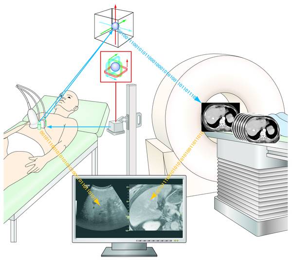
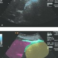
Fig. 32.1 Fusion imaging. A tracking system composed of a stationary magnetic field generator and two sensors mounted on the ultrasound transducer monitors the position, location, and beam direction of the transducer during the ultrasound examination. These spatial coordinates are used to extract a corresponding anatomical section from a previously acquired CT or MRI volume data set and display it side-by-side with or overlaid onto the ultrasound image.
A sensor within range of the transmitter detects the magnetic fields and delivers an output signal whose intensity is proportional to the orientation angle of the sensor relative to the field lines and its distance from the transmitter. Because the angle of incidence of the magnetic field lines rotates 90° at fixed intervals (every 4.2 milliseconds), the output signal from the sensor will tend to vary accordingly. The relationship of the three output levels to one another can then be used to calculate the orientation of the sensor relative to the transmitter. This relationship is easily understood by considering the case of a constant output signal. This can occur only if all three magnetic fields impinge upon the sensor at an identical angle, i.e., at a 45° angle in the x, y, and z axes. This defines its orientation relative to the transmitter.
The angle of the incident field lines can be determined with even greater precision by mounting several (usually three) magnetic field detectors at angles to one another inside one sensor housing.
To determine not just the orientation of the sensor but also its distance from the transmitter (i.e., its position in space), the cumulative intensity of the three signals is measured and compared with a reference value. Since the amplitude of the field declines exponentially with distance from the transmitter, this function can be used to determine the position of the sensor in space.
A tracking system of this kind can monitor the exact three-dimensional position and location of the transducer in real time and make the spatial coordinates available for other linkages.
32.2 Position Marking
The continuous monitoring of transducer position and beam direction allows the examiner to mark points of special interest within the sectional image (e.g., suspicious structures) so that they can be located again from a different perspective, at a different time, or following treatment. This can be done simply by placing a cursor at the center of the targeted structure during the examination. Because the tracking system captures the position and beam direction of the transducer while the cursor position supplies additional information on the lateral and axial relationship of the structure to the transducer, the absolute position of the tagged feature is defined uniquely in three-dimensional space.
When the sectional plane is altered or the region of interest is revisited at a later time, the position marker will reappear on the screen when the active field of view approaches the previously tagged position. The size and shape of the marker symbol indicate the distance to the target, allowing the examiner to very quickly direct the scan plane precisely through the structure of interest.
32.3 Fusion with CT, MRI, or PET Volume Data Sets
One of the most important applications of volume navigation is the precise fusion of live ultrasound images with anatomically corresponding sections from a previously acquired CT, MRI, or PET volume data set. Before the start of the ultrasound examination, the data sets are imported via a network or portable storage device (USB stick, CD, DVD) and loaded into the image memory of the ultrasound system. The data transfer is done in standard DICOM format and generally takes less than 1 minute.
Stay updated, free articles. Join our Telegram channel

Full access? Get Clinical Tree


