Lower Limb II: Knee


Lower Limb II: Knee


Knee

The vulnerability of the knee, the largest joint in the body, to direct trauma makes knee injuries very common throughout life. Most acute injury to the knee is sustained during adolescence and adulthood, with motor vehicle accidents and athletic activities being the major causing factors. Fractures are much more common than dislocations, but injuries to the cartilaginous and soft-tissue structures, such as tears of the menisci and ligaments, are the most common types of injuries, particularly in older adolescents and younger adults. The symptoms accompanying knee trauma vary according to the specific site of injury and thus constitute important indications of the type of injury. However, clinical history and physical examination are rarely sufficient for making a precise diagnosis. Radiologic examination plays a determining role in diagnosing the various traumatic conditions involving the knee joint.


Anatomic-Radiologic Considerations

Conventional radiographs are the first-line approach to the traumatized knee, and often they are sufficient for evaluating many traumatic conditions of the joint. However, the great incidence of cartilaginous and soft-tissue injuries, occurring either as isolated conditions or in association with fractures, requires the use of ancillary imaging techniques for adequate evaluation of the joint capsule, articular cartilage, menisci, and ligaments.

The standard radiographic examination usually consists of obtaining films of the knee in four projections: the anteroposterior, the lateral, and the tunnel projections, as well as an axial view of the patella. The anteroposterior radiograph of the knee allows sufficient evaluation of many of the most important aspects of the distal femur and proximal tibia: the medial and lateral femoral and tibial condyles; the medial and lateral tibial plateaus and tibial spines; and the medial and lateral joint compartments and the head of the fibula (Fig. 9.1). However, the patella is not well demonstrated on this view because it is superimposed on the distal femur. Proper evaluation of this structure requires a lateral projection (Fig. 9.2) on which the relationship of the patella and femur can also be assessed. Proximal (superior) displacement of the patella is called patella alta; distal (inferior) displacement is called patella baja. The length of the patella is measured from its upper pole (base) to the apex. The length of the patellar ligament is measured from its proximal attachment, just above the apex, to the notch on the proximal margin of the tibial tubercle. These two measurements are approximately equal and the normal variation does not exceed 20% (Fig. 9.3). In addition to imaging the patella in profile, the lateral radiograph of the knee allows evaluation of the femoropatellar compartment, the suprapatellar bursa (pouch), and the quadriceps tendon. The femoral condyles overlap on this projection, and the tibial plateaus are demonstrated in profile. Occasionally, a cross-table lateral view of the knee—obtained with the patient supine, the affected leg extended, and the central beam directed horizontally—may be required to demonstrate the intracapsular fatfluid level (FBI sign of lipohemarthrosis; see Fig. 4.36B). An angled posteroanterior projection of the knee, known as the tunnel (or notch) view, is also obtained as part of the standard radiographic examination (Fig. 9.4). This view is useful in visualizing the posterior aspect of the femoral condyles, the intercondylar notch, and the intercondylar eminence of the tibia.

To demonstrate an axial view of the patella, various techniques are available. The one most commonly used provides what has been called the sunrise view (Fig. 9.5). However, the degree of flexion required to obtain this view results in depressing the patella more deeply within the intercondylar fossa; consequently, the articular surfaces of the femoropatellar joint are not well demonstrated, and subtle subluxations of the patella may not be detected. To overcome this limitation, Merchant and colleagues have described a technique for obtaining an axial view of the patella that demonstrates the femoropatellar joint to better advantage (Fig. 9.6). It is particularly effective in detecting subluxations of the patella, because it allows specific measurements to be made of the normal relations of the patella to the femoral condyles. Subtle abnormalities in these relations may not be seen on the standard axial view because of the degree of knee flexion required for that view, which prevents the patella from subluxing.

The measurements of the femoropatellar relations obtainable from Merchant axial projection concern the sulcus angle and the congruence angle (Fig. 9.7). Normally, the sulcus angle, which is described by the highest points of the femoral condyles and the deepest point of the intercondylar sulcus, measures approximately 138 degrees. By dissecting this angle with two lines—a reference line drawn from the apex of the patella to the deepest point of the sulcus and a second line from the lowest point of the patellar articular ridge to the deepest point of the sulcus—Merchant and colleagues were able to determine the degree of congruence, or the congruence angle, of the femoropatellar joint. When the deepest point of the patellar articular ridge fell medial to the reference line, the angle formed was assigned a negative value; when it fell lateral to the reference line, the angle was designated with a positive value.
In 100 normal subjects included in their study, the average congruence angle was -6 degrees. An angle of +16 degrees or greater was found to be associated with various patellofemoral disorders, particularly lateral patellar subluxation (see Fig. 9.42). On occasion, patellofemoral disorders that are more difficult to diagnose may require, as Ficat and Hungerford recommended, additional tangential views obtained with 30, 60, and 90 degrees of knee flexion.


FIGURE 9.1 Anteroposterior view. (A) For the anteroposterior view of the knee, the patient is supine, with the knee fully extended and the leg in the neutral position. The central beam is directed vertically to the knee with a 5- to 7-degree cephalad angulation. (B) The radiograph in this projection sufficiently demonstrates the medial and lateral femoral and tibial condyles, the tibial plateaus and spines, and both the medial and lateral joint compartments. The patella is seen en face as an oval structure between the femoral condyles.


FIGURE 9.2 Lateral view. (A) For the lateral view of the knee, the patient is lying flat on the same side as the affected knee, which is flexed approximately 25 to 30 degrees. The central beam is directed vertically toward the medial aspect of the knee joint with an approximately 5- to 7-degree cephalad angulation. (B) The film in this projection demonstrates the patella in profile, as well as the femoropatellar joint compartment and a faint outline of the quadriceps tendon. The femoral condyles are seen overlapping, and the tibial plateaus are imaged in profile. Note the slight posterior tilt of the tibial plateaus, which normally measures approximately 10 degrees.


FIGURE 9.3 Femoropatellar relationship. The length of the patella and the patellar ligament are approximately equal; normal variability does not exceed 20%.


FIGURE 9.4 Tunnel view. (A) For the tunnel (or notch) projection of the knee, the patient is prone with the knee flexed approximately 40 degrees, with the foot supported by a cylindrical sponge. The central beam is directed caudally toward the knee joint at a 40-degree angle from the vertical. (B) The radiograph in this projection demonstrates the posterior aspect of the femoral condyles, the intercondylar notch, and the intercondylar eminence of the tibia.


FIGURE 9.5 Sunrise view. (A) For an axial (sunrise) view of the patella, the patient is prone, with the knee flexed 115 degrees. The central beam is directed toward the patella with approximately 15-degree cephalad angulation. (B) The radiograph in this projection demonstrates a tangential (axial) view of the patella. Note the deep position of this structure in the intercondylar fossa. The femoropatellar joint compartment is well demonstrated.


FIGURE 9.6 Merchant view. (A) For the Merchant axial view of the patella, the patient is supine on the table, with the knee flexed approximately 45 degrees at the table’s edge. A device keeping the knee at this angle also holds the film cassette. The central beam is directed caudally through the patella at a 60-degree angle from the vertical. (B) On the film in this projection, the articular facets of the patella and femur are well demonstrated.


FIGURE 9.7 Sulcus and congruence angles. Two specific measurements can be obtained from the Merchant axial view: the sulcus angle and the congruence angle. The sulcus angle, formed by lines extending from the deepest point of the intercondylar sulcus (a) medially and laterally to the tops of the femoral condyles, normally measures approximately 138 degrees. To determine the congruence angle, the sulcus angle is bisected to establish a reference line (ba), which is drawn to connect the apex of the patella (b) with the deepest point of the sulcus (a). In normal subjects, this line is close to vertical. A second line (ca) is then drawn from the lowest point on the articular ridge of the patella (c) to the deepest point of the sulcus (a). The angle formed by this line and the reference line is the congruence angle. If the lowest point on the patellar articular ridge is lateral to the reference line, then the congruence angle has a positive value; if it is medial to the reference line, as in the present example, then the angle has a negative value. In Merchant’s study, the average congruence angle in normal subjects was -6 degrees (SD, ± 11 degrees). (Modified from Merchant AC et al., 1974, with permission.)

Among the ancillary techniques available for the evaluation of injuries to the knee, arthrography, computed tomography (CT), and magnetic resonance imaging (MRI) provide crucial information. CT is especially useful in the evaluation of complex fractures of the distal femur, the tibial plateaus, and the patella. In fractures of the tibial plateaus, it is effective in determining the amount of depression of the articular surface and in identifying small comminuted fragments that
may be displaced into the joint, as well as comminution about the tibial spines, which may indicate avulsion of the cruciate ligaments. Tomography, by its ability to demonstrate the integrity of the anterior cortex, is also helpful in planning a surgical approach to the treatment of tibial plateau fractures.


FIGURE 9.8 Arthrography of the knee. For arthrographic examination of the knee, the patient is supine on the radiographic table, with both legs fully extended and in the neutral position. The patella is pulled laterally and rotated anteriorly, and the joint is entered from the lateral aspect at the midpoint of the patella. Before injection of contrast, the joint should be aspirated to avoid dilution of the contrast medium by joint fluid. For a double-contrast study, 40 to 50 mL of room air is injected into the joint, followed by 5 to 7 mL of positive-contrast agent (usually 60% diatrizoate meglumine mixed with 0.3 mL of epinephrine 1:1,000, which delays absorption of the contrast). Radiographs are then obtained in the prone position using the spot-film technique (see Fig. 9.10).

Arthrography used to be the procedure of choice in evaluating injuries to the soft-tissue structures of the knee, such as the joint capsule, menisci, and ligaments (Fig. 9.8). It is still valuable in examination of the articular cartilage, particularly when subtle chondral or osteochondral fracture is suspected, or when confirmation of the presence or absence of osteochondral bodies in the knee joint is required in suspected osteochondritis dissecans. However, in the evaluation of the menisci, cruciate ligaments, and collateral ligaments, arthrographic examination has been almost completely replaced by MRI.

The medial and lateral menisci (or semilunar cartilages) of the knee are crescent-shaped fibrocartilaginous structures attached, respectively, to the medial and lateral aspects of the superior articular surface of the tibia (Fig. 9.9). Normally, the medial meniscus is visualized on arthrography as a triangular structure intimately attached to the joint capsule and tibial (medial) collateral ligament; its smooth borders are coated by positive-contrast agent and surrounded by injected air. The normal arthrogram shows no air or contrast within the substance of the meniscus or at its periphery (Fig. 9.10A-C). Although the lateral meniscus is structurally very similar to the medial meniscus, it has a very important distinguishing feature. The popliteal muscle’s tendon and its sheath pass through a portion of the posterior horn of the lateral meniscus, separating it from the joint capsule. This anatomic site, known as the popliteal hiatus, gives an arthrographic impression of separation of the periphery of the lateral meniscus from the capsule; it should not be mistaken for a tear (Fig. 9.10D,E). An important fact to remember is that not all areas of the menisci are well demonstrated by knee arthrography. Only the parts seen tangentially can be assessed accurately. For example, the posterior part of the posterior horn of the lateral meniscus constitutes a blind spot, because it extends deeply into the knee joint (see Fig. 9.9).

The cruciate ligaments of the knee are also structures commonly subject to injury (Fig. 9.11). In the evaluation of these ligaments, arthrography was the procedure of choice before the MRI era and is even now occasionally performed. The radiograph is obtained to best advantage in the lateral projection with 60 to 80 degrees of knee flexion and with the examiner applying pressure to the posterior aspect of the proximal tibia. When tensed, the anterior cruciate ligament normally projects as a straight line extending from the intercondylar notch to a point approximately 8 mm posterior to the anterior margin of the tibia. The posterior cruciate ligament is seen as a straight or slightly bulging line extending to the posterior margin of the tibial plateau (Fig. 9.12).

In the past decade, MRI of the knee has gained wide acceptance in the diagnosis of traumatic abnormalities, and currently is the method of choice in evaluating various knee structures, particularly the menisci, cruciate ligaments, and collateral ligaments. Routinely, T1-weighted and T2-weighted images are obtained in the sagittal, coronal, and axial planes. The sagittal plane is generally the most effective for evaluation of the cruciate ligaments, menisci, patellar ligament, and quadriceps tendon. Coronal sections are needed for evaluation of the medial and lateral collateral ligaments, as well as the menisci. The axial plane is best to evaluate the patellofemoral joint compartment. The axial plane is also helpful in evaluating the popliteal cysts and their relationship to the surrounding structures of the popliteal fossa.

MR arthrography (MRa) is effective in evaluating residual or recurrent meniscal tears after meniscal surgery. It is also a valuable technique to demonstrate loose intraarticular chondral or osteochondral bodies, synovial plicae, and to evaluate the stability of various osteochondral lesions, including osteochondritis dissecans and osteochondral fracture. MRa of the knee is performed by injecting up to 40 mL of diluted gadolinium solution into the joint using the same technique as described for conventional knee arthrography (see Fig. 9.8). Coronal, sagittal, and axial images are obtained, most commonly with fat-suppressed T1-weighted and T2-weighted sequences.

The menisci are seen on MRI as wedge-shaped or bow-tie-shaped structures of uniformly low signal intensity in practically all pulse sequences (Fig. 9.13). The anterior and posterior cruciate ligaments, like the menisci, are seen as low-signal-intensity structures on all spin echo sequences. The anterior cruciate ligament is straight and fan shaped (slightly wider at its femoral attachment) and demonstrates low-to-intermediate signal intensity (Fig. 9.14A). The posterior cruciate ligament is arcuate in shape when the knee is in extension or mild flexion and becomes increasingly taut as the knee is flexed. Normally, it has very low signal intensity (Fig. 9.14B). Anteriorly to the posterior cruciate ligament, one can observe a small bulge produced by the anterior meniscofemoral ligament, also known as the ligament of Humphrey (Fig. 9.14B,C). Posteriorly, a small bulge is created by the posterior meniscofemoral ligament, known as the ligament of Wrisberg (Fig. 9.14D).

The medial collateral ligament consists of two components: superficial and deep. The superficial component, which is the principal medial stabilizer of the knee, arises from the medial femoral epicondyle just below the adductor tubercle and inserts into the medial aspect of the tibia, approximately 5 cm below the joint line. The deep layer of the medial collateral ligament, which is considered part of the fibrous capsule, attaches loosely to the peripheral margin of the body of the medial meniscus. The lateral collateral ligament attaches to the lateral epicondyle of the femur superiorly just above the popliteus groove, in which region it merges with the outer surface of the capsule. From here it extends inferiorly and posteriorly to attach to the anterior portion of the apex of the fibular head. Both collateral ligaments are best demonstrated
on the images obtained in the coronal plane. Like the menisci and cruciate ligaments, they also display low signal intensity (Fig. 9.15).


FIGURE 9.9 Tibial plateau. In the topography of the tibial plateau, the medial meniscus is a C-shaped fibrocartilaginous structure with anterior horn attached anteriorly to the intercondylar eminence of the tibia and with posterior horn inserted into the intercondylar area in front of the attachment of the posterior cruciate ligament. The anterior horn of the lateral meniscus, which is an O-shaped structure, is attached in front of the lateral intercondylar tubercle, and the posterior horn inserts medially into the lateral intercondylar tubercle, in front of the attachment of the posterior horn of the medial meniscus.


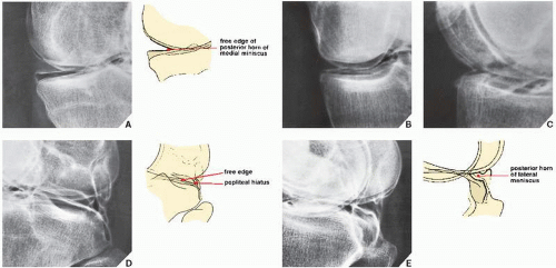
FIGURE 9.10 Arthrography of the knee. Multiple spot films obtained during arthrographic examination of the knee demonstrate the normal appearance of the medial (A,B,C) and lateral (D,E) semilunar cartilages. The contrast-outlined margins of the medial meniscus show its triangular shape. The posterior horn (A) is longer than the body (B) and the anterior horn (C), and the free edge of the meniscus is sharply pointed. Features of the normal lateral meniscus include the gap of the popliteal hiatus, which separates the meniscus from the joint capsule (D). The posterior horn reattaches to the capsule more posteriorly (E). No contrast should be seen within the substance of any aspect of the menisci.


FIGURE 9.11 The cruciate ligaments. In the topography of the cruciate ligaments of the knee, the anterior cruciate ligament arises on the medial surface of the lateral femoral condyle at the intercondylar notch (A) and attaches on the anterior portion of the intercondylar eminence of the tibia (C) (see also Fig. 9.9). The posterior cruciate ligament originates on the lateral surface of the medial femoral condyle within the intercondylar notch (B) and inserts on the posterior surface of the intercondylar eminence (D) (see also Fig. 9.9). Neither cruciate ligament is attached to the tibial tubercles.


FIGURE 9.12 Arthrography of the cruciate ligaments. Double-contrast arthrogram of the knee demonstrates the normal appearance of the cruciate ligaments. Note the angle formed by their projectional intersection and their taut appearance. Each ligament can be traced from its origin in the femur to its insertion in the tibia. The boundaries of the cruciate ligaments are sharply outlined because the contrast medium coats their synovial reflexions. The cruciate ligaments are extrasynovial structures; only the anterior surface of the anterior cruciate ligament and the posterior surface of the posterior cruciate ligament are covered by synovium.


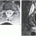
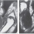
FIGURE 9.13 Appearance of normal menisci on MRI. (A) Anterior and posterior horns of the medial meniscus as seen on sagittal T2*-weighted MPGR sequence (flip angle 30 degrees). (B) Anterior and posterior horns of the lateral meniscus as seen on sagittal T2*-weighted MPGR sequence (flip angle 30 degrees). (C) Body of the medial meniscus as seen on sagittal spin-echo T1-weighted sequence. (D) Anterior and posterior horns of the lateral meniscus as seen on sagittal spin-echo T1-weighted sequence. (E) Schematic representation of topography of the medial and lateral menisci and surrounding structures as seen in the midplane of the coronal MRI. (Modified from Firooznia H, Golimbu C, Rafii M, 1994, with permission.)


FIGURE 9.14 Cruciate ligaments. Spin-echo sagittal MR images (TR 2000/TE 20 msec) of the normal cruciate ligaments. (A) Anterior margin of the anterior cruciate ligament is straight and well defined; the posterior margin is ill defined because of the oblique orientation of the ligament. (B) The posterior cruciate ligament is seen in its entirety, in one plane, from the femoral to the tibial attachments. Observe the small bulge anteriorly produced by the anterior meniscofemoral ligament. (C) In this sagittal section, the anterior meniscofemoral ligament of Humphrey is very prominent, simulating a loose body or meniscal fragment. (D) Here, meniscofemoral ligaments, both anterior (Humphrey) and posterior (Wrisberg), are prominent. (From Beltran J, 1990, with permission.)


FIGURE 9.15 Collateral ligaments. (A) Spin-echo coronal MR image (TR 2000/TE 20 msec) of the normal medial collateral ligament. The medial collateral ligament is well defined in this section through the intercondylar notch. The insertion of the posterior cruciate ligament in the inner aspect of the medial femoral condyle is well demonstrated. The menisci are seen as small triangles of low signal intensity. (B) Spin-echo coronal MR image (TR 2000/TE 20 msec) of the lateral (fibular) collateral ligament. On this posterior section, note the meniscofemoral ligament, which extends from the posterior horn of the lateral meniscus to the inner surface of the medial femoral condyle. The lateral and medial menisci and posterior cruciate ligament are well demonstrated. (From Beltran J, 1990, with permission.)

During evaluation of MRI of the knee, it is helpful to use a checklist as provided in Table 9.1.

Evaluation of knee instability caused by ligament injuries may require obtaining stress views. These techniques are most commonly performed in cases of suspected injury to the medial collateral ligament (Fig. 9.16; see also Fig. 9.74). They are less frequently performed during the evaluation of insufficiency of the anterior and posterior cruciate ligaments (Fig. 9.17). These examinations should preferably be performed under local anesthesia.

Arteriography and venography may need to be used in the evaluation of concomitant injury to the vascular system, although recently more often MR angiography is performed for this purpose. CT is effective in the evaluation of tibial plateau fractures, and it is occasionally used to evaluate injury to the cartilage and soft tissues, particularly the menisci and cruciate ligaments. CT used in conjunction with arthrography (computed arthrotomography) is useful in the evaluation of osteochondritis dissecans (see Fig. 9.54C,D) and in detecting nonopaque osteochondral bodies in the knee joint.

For a summary of the preceding discussion in tabular form, see Tables 9.2 and 9.3 and Figure 9.18.


Injury to the Knee


Fractures About the Knee

Fractures of the Distal Femur. Most often sustained in motor vehicle accidents or falls from heights, fractures of the distal femur are classified according to the site and extension of the fracture line as supracondylar, condylar, and intercondylar. Supracondylar fractures can be further classified as nondisplaced, impacted, displaced, and comminuted (Fig. 9.19). These injuries are usually well demonstrated on the standard anteroposterior and lateral radiographs of the knee (Fig. 9.20); however, in rare instances an oblique view of the knee may be needed to evaluate an obliquely oriented fracture line. Tomography used to be required in cases of comminution for a full evaluation of the fracture lines and localization of the fragments (Fig. 9.21), although currently helical CT with multiplanar and 3D reformation has surpassed conventional tomographic technique (Fig. 9.22).

Fractures of the Proximal Tibia. The medial and lateral tibial plateaus are the most common sites of fractures of the proximal tibia. Because they usually result when the knee is struck by a moving vehicle, they are also called “fender” or “bumper” fractures; some, however, may be the result of twisting falls. The Hohl classification gives an overview of six different types of tibial plateau fractures and is useful in correlating the various types of injuries with the applied forces causing them (Fig. 9.23). In the Hohl classification, pure abduction injury results in a nondisplaced split fracture of the lateral tibial plateau (type I) (Fig. 9.24). When axial compression is combined with abduction force, local central depression (type II) and local split depression (type III) fractures occur (Fig. 9.25). Total depression fractures (type IV), which are more commonly seen in the medial tibial plateau because of its anatomic configuration (absence of the fibula), are characterized by the lack of comminution of the articular surface. Type V fractures in the Hohl classification, which are infrequently encountered, are local split fractures without central depression involving the anterior or posterior aspects of the tibial plateau. Comminuted fractures involving both tibial plateaus and having a Y or T configuration (type VI) usually result from vertical
compression, such as a fall on the extended leg (Fig. 9.26). Types III and VI are frequently associated with fracture of the proximal fibula. In our institution we use the Schatzker classification of tibial plateau fractures which, similar to the Hohl classification, arranges tibial plateau fractures into VI types, but according to involvement of the medial or lateral plateau (Fig. 9.27).


TABLE 9.1 Checklist for Evaluation of MRI of the Knee


Osseous Structures


Femoral condyles (c, s, a)


Tibial plateau (c, s)


Gerdy tubercle (s, a)


Patella (c, s, a)


Proximal fibula (c, s, a)


Cartilaginous Structures


Articular cartilage (c, s, a)


Joints


Femorotibial (c, s)


Femoropatellar (s, a)


Menisci


Medial (c, s)


Lateral (c, s)


Ligaments


Medial collateral—deep and superficial fibers (c)


Lateral collateral complex—biceps femoris tendon, lateral collateral ligament (LCL) proper, iliotibial band (c)


Anterior cruciate—anteromedial and posterolateral bundles (c, s)


Posterior cruciate (c, s)


Meniscofemoral—Humphry (anterior) and Wrisberg (posterior) (c, s)


Transverse (s)


Patellar (“tendon”) (s)


Patellar retinaculae—medial and lateral (a)


Arcuate (c, a)


Popliteofibular (c, s)


Fabellofibular (c)


Muscles and Their Tendons


Quadriceps (s, a)


Popliteus (c, s)


Plantaris (a)


Biceps femoris (c)


Semimembranosus (s, a)


Semitendinosus (s, a)


Gracilis (s, a)


Sartorius (s, a)


Gastrocnemius (s, a)


Soleus (s, a)


Bursae


Popliteal (Baker)—between the tendons of the medial head of gastrocnemius and semimembranosus (s, a)


Prepatellar (s, a)


Deep infrapatellar (s, a)


Pes anserinus (c)


Semimembranosus—tibial collateral ligament (c)


Other Structures


Synovial plicae (c, a)


Infrapatellar plica (s)


Hoffa fat pad (s, a)


Popliteus hiatus (c)


Popliteal artery and vein (a)


Lateral geniculate artery (c)


Tibial and peroneal nerves (a)


The best imaging planes for visualization of listed structures are given in parenthesis; c, coronal; s, sagittal; a, axial.


FIGURE 9.16 Valgus stress. For a stress film of the knee evaluating the medial collateral ligament, the patient is supine, with the knee flexed approximately 15 to 20 degrees. The leg is placed in the device, and the pressure plate is applied against the lateral aspect of the knee. (The arrows show the direction of the applied stresses.) Films are then obtained in the anteroposterior projection (see Fig. 9.74B).


FIGURE 9.17 Anterior-drawer stress. For a stress film of the knee evaluating the anterior cruciate ligament, the patient is placed in the device on his or her side, with the knee flexed 90 degrees. The pressure plate is applied against the anterior aspect of the knee. (The arrows show the direction of the applied stresses.) Films are then obtained in the lateral projection.


TABLE 9.2 Standard and Special Radiographic Projections for Evaluating Injury to the Knee


Projection


Demonstration


Anteroposterior


Medial and lateral joint compartments


Varus and valgus deformities


Fractures of:


Medial and lateral femoral condyles


Medial and lateral tibial plateaus


Tibial spines


Proximal fibula


Osteochondral fracture


Osteochondritis dissecans (late-stage)


Spontaneous osteonecrosis


Pellegrini-Stieda lesion


Overpenetrated


Bipartiite or multipartite patella


Fractures of patella


Stress


Tear of collateral ligaments


Lateral


Femoropatellar joint compartment


Patella in profile


Suprapatellar bursa


Fractures of:


Distal femur


Proximal tibia


Patella


Sinding-Larsen-Johansson disease*


Osgood-Schlatter disease*


Osteochondral fracture


Osteochondritis dissecans (late stage)


Spontaneous osteonecrosis


Joint effusion


Tears of:


Quadriceps tendon


Patellar ligament


Stress


Tears of cruciate ligaments


Cross-table


FBI sign of lipohemarthrosis


Tunnel (posteroanterior)


Posterior aspect of femoral condyles


Intercondylar notch


Intercondylar eminence of tibia


Axial (sunrise and Merchant)


Articular facets of patella


Sulcus angle


Congruence angle


Fractures of patella


Subluxation and dislocation of patella


* These conditions are best demonstrated using a low-kilovoltage/soft-tissue technique.

These features are better demonstrated on Merchant axial view.


TABLE 9.3 Ancillary Imaging Techniques for Evaluating Injury to the Knee


Technique


Demonstration


Arthrography (usually double-contrast; occasionally single contrast using air only)


Meniscal tears


Injuries to: Cruciate ligaments Medial collateral ligament Quadriceps tendon Patellar ligament Joint capsule


Chondral and osteochondral fractures


Osteochondritis dissecans (early and late stages)


Osteochondral bodies in joint


Subtle abnormalities of articular cartilage


Computed Tomography and Computed Arthrotomography


Spontaneous osteonecrosis


Injuries to: Articular cartilage Cruciate ligaments Menisci


Osteochondral bodies in joint


Osteochondritis dissecans


Radionuclide Imaging (scintigraphy, bone scan)


Subtle fractures not demonstrated on standard studies


Early and late stages of Osteochondritis dissecans Spontaneous osteonecrosis


Angiography (arteriography, venography)


Concomitant injury to arteries and veins


Magnetic Resonance Imaging


Same as arthrography, CT, and radionuclide imaging


Magnetic Resonance Arthrography


Residual or recurrent meniscal tears


Complications after meniscal surgery


Loose intraarticular bodies


Synovial plicae


Stability of osteochondral lesions


Tears of collateral ligaments


Tears of cruciate ligaments


Magenetic Resonance Angiography


Same as angiography


FIGURE 9.18 Spectrum of radiologic imaging techniques for evaluating injury to the knee.*

*The radiographic projections or radiologic techniques indicated throughout the diagram are only those that are the most effective in demonstrating the respective traumatic conditions.

#Almost completely replaced by CT.


FIGURE 9.19 Classification of distal femur fractures. Fractures of the distal femur can be classified according to the site and extension of the injury as supracondylar, condylar, and intercondylar fractures.


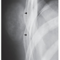
FIGURE 9.20 Supracondylar fracture. A 58-year-old man was injured in a motorcycle accident. Anteroposterior (A) and lateral (B) radiographs of the knee demonstrate a comminuted supracondylar fracture of the distal femur. The extension of the fracture lines and the position of the fragments can be assessed adequately on these standard studies.


FIGURE 9.21 Supracondylar fracture. A 22-year-old racing car driver was injured in an accident on the track. (A) Anteroposterior view of the right knee shows a comminuted fracture of the distal femur. Tomography was performed, and sections in the anteroposterior (B) and lateral (C) projections demonstrate intraarticular extension of the fracture lines, with split of the condyles and posterior displacement of the distal fragments. The multiple comminuted fragments can be localized.


FIGURE 9.22 CT and 3D CT of supracondylar fracture. A 54-year-old woman was injured in a motor vehicle accident. (A) Anteroposterior radiograph of the right knee shows markedly comminuted supracondylar fracture of the femur. (B,C) Coronal and sagittal reformatted CT images show displacement of various fracture fragments. Three-dimensional CT reconstructed images, (D) oblique and (E) viewed from the posterior aspect, depict the position and orientation of displaced fracture fragments in more comprehensive fasion.


FIGURE 9.23 The Hohl classification of fractures of the tibial plateau. (Modified from Hohl M, 1967, with permission.)


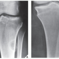
FIGURE 9.24 Fracture of the tibial plateau. A 30-year-old man was hit by a car while he was crossing the street. Anteroposterior radiograph (A) and tomogram (B) show a split fracture of the lateral tibial plateau (Hohl type I).


FIGURE 9.25 Fracture of the tibial plateau. Anteroposterior radiograph of the knee shows the appearance of a tibial plateau fracture, which is a combination of wedge and central depression fractures involving the lateral tibial condyle (Hohl type III).

Fractures of the tibial plateau may not be obvious on the routine radiographic examination of the knee, particularly if there is no depression (Fig. 9.28A,B). In such cases, however, the cross-table lateral projection often reveals the FBI sign, which indicates the presence of an intraarticular fracture (Fig. 9.28C). Demonstration of an obscure fracture line may require oblique projections.

Only gold members can continue reading. Log In or Register to continue

Stay updated, free articles. Join our Telegram channel

Jul 24, 2016 | Posted by in MUSCULOSKELETAL IMAGING | Comments Off on Lower Limb II: Knee

Full access? Get Clinical Tree

Get Clinical Tree app for offline access