Pelvis, Hips, and Thighs
Thomas H. Berquist
Protocols
Routine radiographs
Pelvis
Anteroposterior (AP) to include from iliac crest to below lesser trochanters
For trauma, use inlet (tube angled 45 degrees to the feet) and outlet (tube angled 45 degrees to the head) AP views
Hips
AP view, frog-leg oblique, or lateral for screening
AP plus Judet (45 degrees anterior and posterior obliques of involved side) views for acetabular trauma
Femurs
AP and lateral to include hip and knee joints
Computed tomography (CT) (bone and soft tissue windows should be studied)
Pelvis
Axial 5-mm or 1-cm sections iliac crest to below lesser trochanters for screening
Hips
Axial 1-mm sections at 0.5-mm intervals to be reformatted in coronal, sagittal, or three-dimensional, depending on indication (i.e., sagittal reformatting is useful to classify acetabular fractures).
MAGNETIC RESONANCE IMAGING
| Region | Pulse Sequence | Thickness/Skip | Matrix | FOV | Acquisitions |
|---|---|---|---|---|---|
| Pelvis/SI Joints | Coronal SE 410/17 | 6 mm | 512 × 512 | 34–40 | 2 |
| Axial 580/13 | 5 mm | 512 × 512 | 34–40 | 1 | |
| Axial FSE 4000/102 | 6 mm | 512 × 512 | 34–40 | 2 | |
| Coronal STIR 5600/109/165 | 5 mm | 256 × 256 | 34–40 | 2 | |
| Hips | Coronal SE 536/15 | 4 mm | 256 × 256 | 20–24 | 1 |
| Axial FSE 4000/102 | 6 mm | 512 × 512 | 20–24 | 2 | |
| Sagittal SE 536/15 | 4 mm | 256 × 256 | 20–24 | 1 | |
| Thighs | Axial FSE 4000/102 | 6 mm | 512 × 512 | 30–42 | 2 |
| Coronal or sagittal SE 536/15 | 4 mm | 256 × 256 | 30–42 | 1 | |
| Arthrography | Axial SE 568/15 | 4 mm | 256 × 256 | 18 | 1 |
| Sagittal SE 568/15 | 4 mm | 256 × 256 | 18 | 1 | |
| Coronal SE 450/15 | 4 mm | 256 × 256 | 18 | 1 | |
| Coronal FSE 4000/102 | 4 mm | 256 × 256 | 18 | 1 | |
| Oblique coronal SE 420/15 | 4 mm | 256 × 256 | 18 | 1 | |
| Oblique sagittal SE 420/15 | 4 mm | 256 × 256 | 18 | 1 | |
| SI, sacroiliac; FSE, fast-spin echo; SE, spin-echo; STIR, short TI inversion recovery; FOV, field of view. | |||||
Additional Options
Intravenous gadolinium
Neoplasms
Early synovial inflammation
Infection
Early avascular necrosis (AVN)
Intra-articular gadolinium (8 to 20 mL of 1 mmol solution)
Labral tears
Subtle cartilage lesions
Loose bodies, synovial chondromatosis
Trauma: Pelvic Fractures—Minor
Key Facts
Mechanism of injury—fall or minor trauma
Usually older age group
Fractures of individual bones or single break in pelvic ring
Minor fractures account for 25% of pelvic fractures
Common minor fractures
Avulsion fractures (Fig. 4-1)
Ischial fractures
Pubic rami fractures
Transverse sacral fractures (up to 70% missed on routine radiographs)
Complications—pain, rarely significant complications compared with complex fractures.
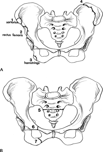 FIGURE 4-1 Common minor fractures of the pelvis. (A) Anterior superior iliac spine (1), anterior inferior iliac spine (2), ischial tuberosity (3), and iliac wing (4). One to three are avulsion injuries with muscles labeled. (B) Transverse sacral fracture (5), isolated pubic rami fractures (6 and 7). |
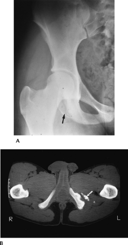 FIGURE 4-2 (A) AP radiograph of the hip demonstrating an ischial avulsion fracture. (B) CT image of an old ischial avulsion fracture. |
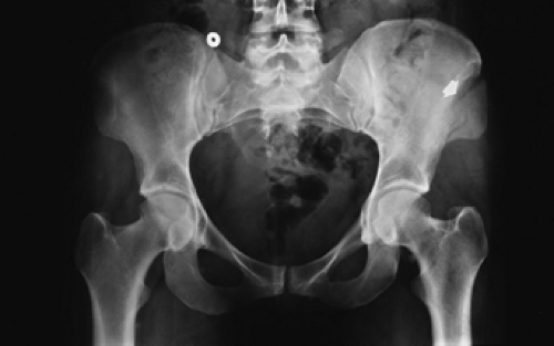 FIGURE 4-3 AP radiograph demonstrating an iliac wing fracture (arrow). |
Suggested Reading
Young JWR, Resnick C. Fractures of the pelvis: Current concepts in classification. AJR Am J Roentgenol 1990;155:1169–1175.
Trauma: Pelvic Fractures—Single Break In Pelvic Ring
Key Facts
Mechanism of injury—minor trauma
Usually undisplaced pubic rami fractures involving one side
Account for approximately one third of pelvic fractures
Complications—pain, local hematoma
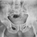
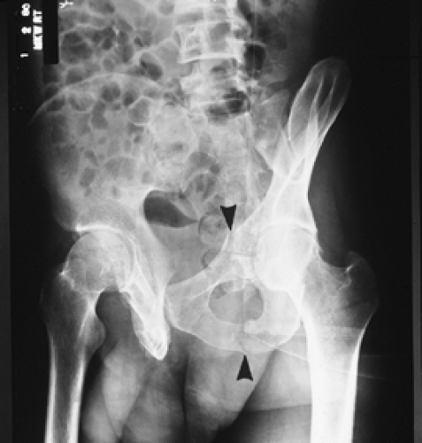 FIGURE 4-4 Anterior Judet view demonstrating pubic rami fractures (arrowheads) resulting in a single break in the pelvic ring. |
Suggested Reading
Berquist TH. Imaging of orthopedic trauma. 2nd ed. New York: Raven Press; 1992:207–310.
Mucha P, Farnell MB. Analysis of pelvic fracture management. J Trauma 1984;24:379–386.
Trauma: Pelvic Fractures—Complex
Key Facts
Mechanism of injury—high-velocity trauma, such as a motor vehicle accident
Lateral compression (41%–72% of cases)
AP compression (15%–25% of cases)
Vertical shearing injuries (6% of cases)
Combined mechanisms (14% of cases)
Two or more breaks in the pelvic ring
Occur in younger age group (52% are less than 30 years of age)
Complications may be severe100% result from multiple complications.” class=HASTIP>*
Hemorrhage
71%
Other associated fractures
65%
Genitourinary
22%
Neural injury
21%
Head injury
11%
Chest injury
11%
Abdomen injury
11%
Additional imaging, specifically CT, is usually required to define extent of injury.
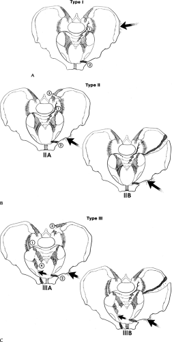 FIGURE 4-5 Lateral compression injuries. (A) Type I: force applied posterolaterally (arrow) resulting in a crush injury to the sacrum, ilium, and sacroiliac joint (1) and oblique or horizontal pubic rami fractures (2). (B) Type II: force directed anterolaterally (arrow) resulting in diastasis of the sacroiliac joint (1 and 3) (Type IIA) or iliac wing fracture (Type IIB) plus oblique or horizontal pubic rami fractures (2). (C) Type III: force applied anterolaterally (arrow) with oblique or horizontal pubic rami fractures (2) and involvement of both sacroiliac joints and ligaments (1, 3, and 4) (Type IIIA) or sacroiliac joints and ipsilateral iliac wing fracture (Type IIIB). |
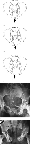 FIGURE 4-6 AP compression injuries. (A) Type I: force applied anteriorly (arrow) resulting in diastasis of the pubic symphysis or vertical pubic rami fractures. (B) Type II: wider diastasis of the pubic symphysis or vertical pubic rami fractures with disruption of the anterior sacroiliac ligaments. (C) Type III: wider diastasis of the pubic symphysis or displaced vertical pubic rami fractures with disruption of both the anterior and posterior sacroiliac ligaments. (D) AP compression injury with vertical pubic rami fractures. Sacroiliac joints are normal. Note the elevated bladder resulting from a large pelvic hematoma. Type I. (E) Type III AP compression injury with wide diastasis of the pubic symphysis, displaced iliac wing fracture (white arrow), widening of the right sacroiliac joint (black arrow), and multiple avulsion fractures (arrowheads). |
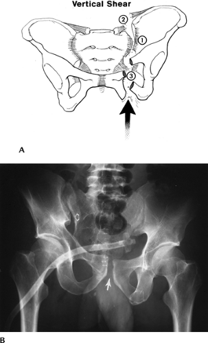 FIGURE 4-7 Vertical shearing injury. (A) Force is applied vertically (arrow) with vertical pubic rami fractures (3) or step-off at the pubic symphysis and disruption of the anterior and posterior sacroiliac ligaments (1 and 2). (B) Widening and step-off of the right sacroiliac joint (open arrow) and symphysis (arrow). Suprapubic tube in the bladder because of associated urethral injury. |
Suggested Reading
Failinger S, McGarrity PL. Unstable fractures of the pelvic ring. J Bone Joint Surg 1992;74A:781–791.
Young JWR, Resnick C. Fractures of the pelvis: current concepts and classification. AJR Am J Roentgenol 1990;155:1169–1175.
Trauma: Acetabular Fractures—Simple
Key Facts
Mechanism of injury—lower extremity trauma with force directed to the femoral head.
Fractures involve posterior acetabulum if hip flexed. Posterior dislocation may occur.
Transverse and anterior fractures occur with lateral blow to greater trochanter.
AP and Judet views may detect injury. CT with coronal and sagittal reformatting is useful to evaluate and characterize subtle fractures and the joint space involvement.
Complications—minor, or arthrosis in later years.
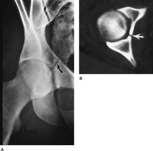 FIGURE 4-8 (A) Judet view of the hip demonstrating and undisplaced central acetabular fracture (curved arrow). (B) CT image demonstrating an uncomplicated central acetabular fracture (arrow). |
Suggested Reading
Letournel E. Acetabular fracture classification and management. Clin Orthop 1980;151:81–106.
Trauma: Acetabular Fractures—Complex
Key Facts
Multiple fracture classification systems have been proposed.
Two-column, transverse with posterior wall involvement, and posterior wall fractures account for 66% of acetabular fractures. “T” and transverse fractures are the next two most common injury patterns. These five patterns account for 90% of acetabular fractures.
Definition of extent of articular and anterior and posterior column involvement is critical for treatment planning.
CT with reformatting in sagittal and coronal planes or three-dimensional reconstruction is essential.
Complications are similar to complex pelvic fractures (see section on Pelvic Fractures—Complex).
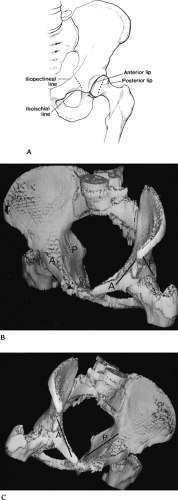 FIGURE 4-9 (A) Acetabular margins and the anterior (iliopectineal) and posterior (ilioischial) columns. Three-dimensional CT images (B,C) demonstrating the anterior and posterior columns. |
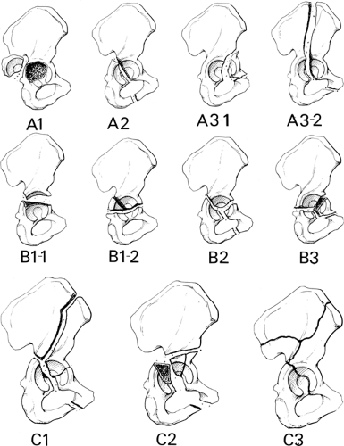 FIGURE 4-10 Fracture patterns (AO classification). (A) Type A: A1, posterior wall fracture; A2, posterior column fracture; A3-1, anterior wall fracture; A3-2, anterior column fracture. (B) Type B1-1, transverse fracture; Type B1-2, transverse with posterior wall fracture; Type B2-T, fracture; Type B3, anterior column with posterior transverse fracture. (C) Type C1, both columns with fracture extending to the iliac crest; Type C2, both columns extending to anterior inferior iliac spine; Type C3, both columns with extension to sacroiliac joint. Types A1, B1-1, B1-2, B-2, and C1 are the most common. |
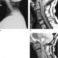
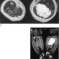
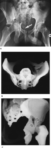 FIGURE 4-11 Complex acetabular fractures. (A) AP radiograph shows a displaced central acetabular fracture with the femoral head and fragments extending into the pelvis. Note the coccygeal dislocation (arrow). Three-dimensional reconstructions (B,C) of a complex acetabular fracture (arrows). |
Suggested Reading
Brandser E, Marsh JL. Acetabular fractures: Easier classification with a systematic approach. AJR Am J Roentgenol 1998;171:1217–1228.
Saks BJ. Normal acetabular anatomy for acetabular fracture assessment. CT and plain film correlation. Radiology 1986;159:139–145.
Trauma: Fracture/Dislocation—Dislocation of the Hip
Key Facts
Hip dislocations account for 5% of all skeletal dislocations.
Mechanism of injury—high-velocity trauma, usually in young adults
Posterior dislocations—10 times more common than anterior. Compressive force to foot or knee with hip flexed. Posterior acetabular fractures are common.
Anterior dislocations—forced abduction and external rotation. Femoral head and anterior acetabular fractures are common.
Up to 75% have multiple other injuries.
Most complete dislocations are obvious on the AP view of pelvis or involved hip.
CT is useful for complete evaluation of the joint space and associated fractures, especially after reduction.
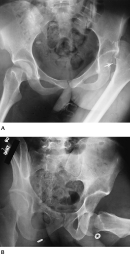 FIGURE 4-12 AP radiographs of posterior (A) and anterior (B) dislocations. Note the displaced femoral head fragment (arrow) in (A). |
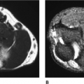
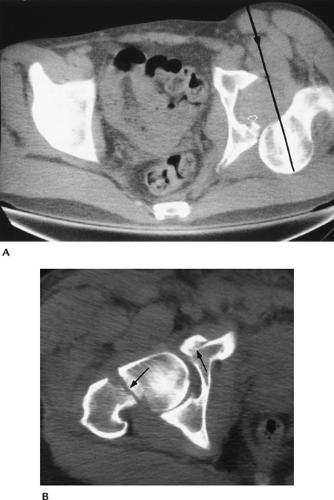 FIGURE 4-13 (A) CT image of a posterior dislocation. Direction of the force (line with arrowhead). Small posterior rim fracture (open arrow). (B) CT image after reduction of an anterior dislocation with fractures of the femoral neck and anterior acetabulum (arrows). |
Suggested Reading
Richardson P, Young JWR, Porter D. CT detection of cortical fracture of the femoral head associated with posterior dislocation of the hip. AJR Am J Roentgenol 1990;155:93–94.
Rosenthal RE, Coher WL. Fracture dislocations of the hip: An epidemiological review. J Trauma 1979;19:572–581.
Trauma: Femoral Neck Fractures
Key Facts
Occur in the elderly and in females more than males
Mechanism of injury—minimal trauma or fall
Garden classification
Type I: incomplete involving lateral cortex
Type II: complete, but undisplaced
Type III: partially displaced
Type IV: completely displaced
Some prefer undisplaced (Types I and II) and displaced (Types III and IV)
Imaging of subtle undisplaced fractures may require radionuclide scanning or magnetic resonance imaging (MRI) for detection. Displaced fractures usually are obvious on routine radiographs.
Complications
Mortality 10% to 20% in the first 30 days after injury and surgery
Mortality approximately 30% first year after injury
AVN common with displaced fractures
Treatment—pin undisplaced and endoprostheses used for displaced fractures because of high incidence of avascular necrosis (AVN).
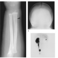
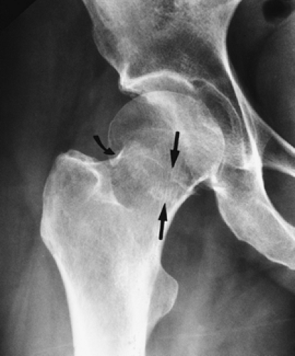 FIGURE 4-14 Impacted femoral neck fracture (arrows) with cortical disruption and trabecular compression laterally (curved arrow). The hip was pinned. |
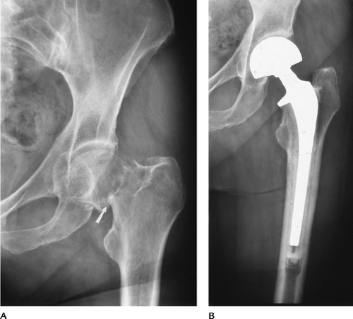 FIGURE 4-15 (A) Displaced femoral neck fracture (arrow). (B) Treated with bipolar endoprosthesis. |
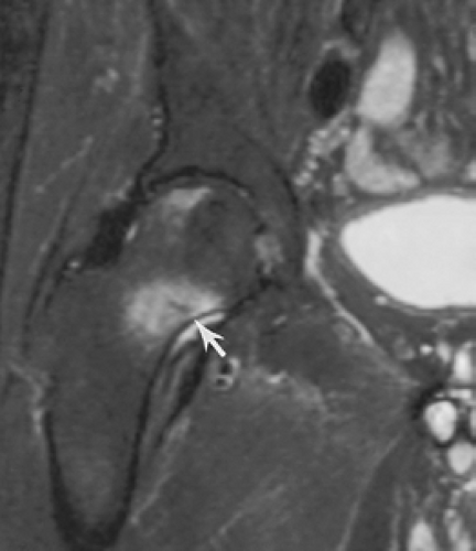 FIGURE 4-16 Coronal fast spin-echo T2-weighted image demonstrates edema with a central linear low-intensity line (arrow) caused by femoral neck stress fracture. |
Suggested Reading
Berquist TH. Imaging atlas of orthopedic appliances and prostheses. New York: Raven Press; 1995:217–352.
Garden RS. Stability and union of subcapital fractures of the femur. J Bone Joint Surg 1964;64B:630–712.
Morgan CG, Wenn RT, Sikand M, et al. Early mortality after hip fracture: Is delay before surgery important. J Bone Joint Surg 2005;87A:483–490.
Trauma: Trochanteric Fractures
Key Facts
Three types of fracture: avulsion, intertrochanteric, and subtrochanteric
Intertrochanteric fractures
Most common in elderly because of falls
Extracapsular; comminution of fracture with detachment of trochanters common
Significant mortality (18%–30%) in year of injury
Subtrochanteric fractures
More common in younger patients with high-velocity trauma
Reduction more difficult to maintain than intertrochanteric fractures
Avulsion fractures
Caused by abrupt muscle contraction (Fig. 4-17)
Occur in active athletes
Greater trochanteric avulsions also seen in elderly patients
Routine radiographs usually are diagnostic
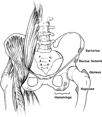 FIGURE 4-17 Sites for avulsion fractures in the pelvis and hips with muscle origins labeled. |
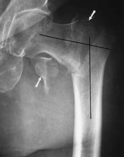 FIGURE 4-18 AP radiograph of a comminuted intertrochanteric fracture. Trochanters (arrows) and angular deformity (lines). |
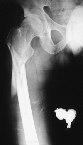 FIGURE 4-19 AP radiograph of a subtrochanteric fracture with overriding and slight angulation of the fragments. |
Suggested Reading
Jensen JS. Classification of trochanteric fractures. Acta Orthop Scand 1980;51:803–810.
Lorich DG, Geller DS, Nelson JH. Osteoporotic peritrochanteric hip fractures. J Bone Joint Surg 2004;86A:398–410.
Trauma: Insufficiency Fractures
Insufficiency fractures occur because of normal stress on bone with abnormal elastic resistance.
Insufficiency fractures most commonly involve the sacrum, pubic rami, and supra-acetabular regions and femoral necks.
Most insufficiency fractures occur in elderly osteopenic patients or patients on steroid therapy.
Patients present with back, hip, or groin pain.
Because of the patient’s age, metastatic disease often is included in the differential diagnosis.
Image features
Radiographs: bone sclerosis or condensation, typically linear.
Radionuclide scans: increased tracer in area of fracture. Bilateral sacral fractures give “H” appearance (Honda sign).
MRI: marrow edema pattern (increased signal on T2-weighted images, decreased signal on T1-weighted images) with or without visible fracture line.
CT: fracture lines clearly defined.
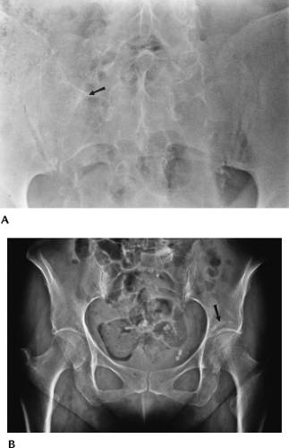 FIGURE 4-20 Radiographs of insufficiency fractures. (A) Radiograph demonstrates subtle bone condensation in the sacrum (arrow) caused by an insufficiency fracture. (B) AP radiograph of the pelvis with linear condensation in the left acetabulum (arrow) caused by an acetabular insufficiency fracture. |
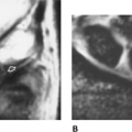
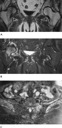 FIGURE 4-21 MRI of insufficiency fractures. Coronal T1- (A) and fast spin-echo T2- (B) weighted images show abnormal signal intensity in the acetabulum on the right caused by insufficiency fracture. There is also marrow edema in the femoral head and neck caused by early AVN. (C) Axial fast spin-echo T2-weighted image of the sacrum with and insufficiency fracture and fluid (arrow) in the fracture line. |
Suggested Reading
Pek WCG, Khong PL, Yur Y, et al. Imaging of pelvic insufficiency fractures. Radiographics 1996;16:335–348.
Trauma: Soft Tissue Trauma
Key Facts
Soft tissue injuries to the pelvis, hips, and thighs may include
Muscle/tendon injuries
Ligament injuries
Neurovascular injuries
Acetabular labral tears
Bursitis
Snapping tendon syndromes
Greater trochanteric pain syndrome
Imaging approaches vary with suspected clinical condition.
| Condition | Imaging Approach |
|---|---|
| Muscle/tendon injury | MRI |
| Ligament injury | MRI, arthrography, or magnetic resonance (MR) arthrography for hip |
| Neurovascular injury | MRI |
| Acetabular labral tears | MR arthrography |
| Bursitis | Ultrasound or MRI |
| Snapping tendon syndrome | Tendon injection with motion studies, ultrasound |
Suggested Reading
Related posts:
Stay updated, free articles. Join our Telegram channel

Full access? Get Clinical Tree


