, Carlos Capuñay1, Carlos E. Sueldo2 and Juan Mariano Baronio3
(1)
Diagnóstico Maipú, Buenos Aires, Argentina
(2)
University of California, San Francisco, CA, USA
(3)
CEGYR, Buenos Aires, Argentina
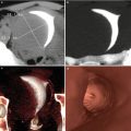
Computed tomography (CT) is the imaging diagnosis method of high complexity most used in clinical practice. It was born in the 70s by the hand of English engineer Sir Godfrey N. Hounsfield [1–3] and has been subject to, over the past four decades, numerous technological changes, transforming into, today, the pillar of all imaging methods utilized in the study of patients with tumors located outside of the central nervous system. The development of the helical (spiral) or volume CT in the early 90s, and the incorporation of the multislice technology at the end of this decade, generated a great impact on the diagnostic capability of the technique [4–10]. The medical community disposes of a variety of non-invasive CT studies that over time have modified the traditional prevention and treatment algorithms. Among them, the angiographies in diverse vascular territories, including the coronary arteries and the pulmonary venous mapping in patients with refractory atrial fibrillation who are candidates for a radiofrequency ablation, or the CT brain perfusion on patients with acute cerebral ischemia. A separate group of studies is one that includes those that utilize virtual imaging reprocessing, highlighting the virtual colonoscopy, a diagnosis procedure that, for the past 15 years, has managed to earn a place in screening for colorectal cancer, as well as the recently developed virtual hysterosalpingography technique.
It is important to make emphasis on the fact that the excellent performance and current role of CT in the decision-making of a diversity of different clinical entities is due to the arrival of the new multidetector row units, which supply an excellent space-time resolution, and in this way, optimize the use of intravenous contrast substances and, with the incorporation of innovative techniques in the processing of raw data, achieve a significant reduction in the radiation dose to which patients are exposed to on a daily basis [11–17].
Before delving into the concepts of this new generation of CT scanners, a brief description of its technique and evolution from its origins will take place.
Basic Concepts
The CT equipment is used to obtain axial (transversal) images on the axis of the human body, basing its operation on the measurement of attenuation that the X-rays beam undergoes in each voxel when crossing the different anatomical structures of the region subject to study. This absorption of the ionizing radiation is established by the lineal coefficient particular to each matter or substance that is pierced by the X-rays beam. The final product is a matrix of numbers, to each of which is assigned a shade of gray to produce the typical CT image. The Hounsfield units are universally used in the scale, in which water is assigned the value 0, and air −1,000.
Components of a CT Scanner
Gantry
Based on the introduction of slip ring technology, continuous rotation of the X-ray tube and the detector became possible. Larger volume coverage in shorter scan times and improved longitudinal resolution became feasible after the introduction of multislice CT systems in 1998. The gantry constitutes the frame on which the following are assembled (Fig. 1.1): the X-ray tube, the crown of detectors, the high voltage generator and the data measurement system. In these third-generation CT scanners, the X-ray tube and detector are built onto a rotation system that rotates around the patient, covering a scan field of view of 50 cm. The main challenge is the stability of both focal spot and detector position during rotation, in particular with regard to the high rotational speeds (0.20 s) and gravitational forces of latest CT systems. Also in the gantry are assembled the cooling system, the position and speed censors, the hydraulic apparatus for the inclination of the gantry, the system used for the ascent, descent, and braking of the CT table, and finally the microphones and loudspeakers used for intercommunication with the patient.
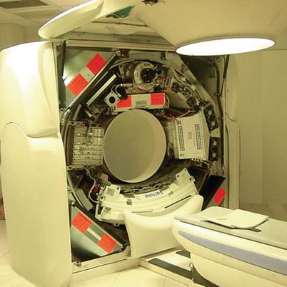
Fig. 1.1
Photo of gantry of a third generation MSCT scanner
X-Rays Generating System
Collimator and X-Rays Tube
The tube is the vacuum device that generates the X-rays beam. A state-of-the-art X-ray tube provides a peak power of 70 kW at various voltages (80 kV, 100 kV, 120 kV, 140 kV). It is formed, on one end, by the cathode (tungsten filament), which when circulating an electrical current, and turned incandescent, generates a flow of electrons towards the anode where they impact. When the electrons, which posses a great kinetic energy, hit the anode, they transfer all their energy, which converts mostly into heat (99 %), and 1 % into X-rays. The size of the anode plate determines the heat storage capacity and the performance level of the tube/generator unit. In the present, fast anode cooling (e.g. the rotating envelope tube design) and high power scans in rapid succession can be performed.
The surface on which said impact takes place is called the focal spot, and its characteristics will depend on the generated X-rays beam’s quality. An image with great detail is obtained with a small focal spot. The X-rays tube is encapsulated in a metal or glass structure, surrounded by a shield (dome) which offers protection against secondary radiation (Fig. 1.2).
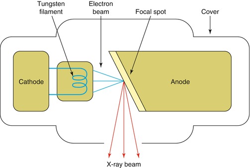
Fig. 1.2
Layout of an X-ray tube
Generator
The high-tension generator is the power circuit that supplies the X-rays tube with the correct voltage for its operation. In other words, it provides the necessary current to heat the cathode filament, as well as to accelerate the electrons. The sharpness and contrast of the CT image taken is highly influenced by the generator’s characteristics. They can be of high or low frequency, continuous or pulsating. Currently, the system most used is the continuous emission one that transforms the web tension into a continuous tension, and then transmits it to a converter that transforms it into a squared pulse beam with a frequency of 15 kHz, with a pulse width that will depend on the kilovoltage, on the miliamperage and on the exposure time chosen.
Detection System
Detectors
In general, CT systems use solid state detectors. Each detector element consists of a radiation-sensitive solid-state material, which converts the absorbed X-rays into visible light. This light is detected by a photodiode and the electrical current is amplified and converted into a digital signal, which then will be used in the imaging reconstruction process. These devices measure the quantity of photons that pass through the section of study, the signal received being proportional to the density of the elements that constitute the object of study. The structure of the detectors is alternating. Their composure, size and design shift constantly so as to find a fast response speed to the variations in radiation. They must be stable, with an ample dynamic range, little dependence on temperature, and low decay times. There are three classes of detectors: (i) with photomultipliers; (ii) with semiconducting photodiodes; (iii) and with pressurized Xenon gas chambers (Fig. 1.3).
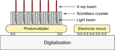
Fig. 1.3
Diagram of a CT detector
Data Measurement Unit
It constitutes the link between the detectors and the processing and storage of data system. This unit integrates the electrical signals received from the detectors, amplifies, and sends them in the form of numbers, using a binary code, to the computer. It generates a digital and analogical conversion. The stream of data generated by the current CT systems is a challenge for data transmission off the gantry and for real-time data processing in the subsequent image reconstruction systems.
Data Management Console
Imaging Processing and Reconstruction
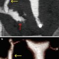
The traditional CT image formation process belongs to the first generation of imaging reconstruction methods and is called filtered back-projection. This algorithm is characterized for its speed in deteriorating the high noise in the image, which is accomplished with the use of filters (Kernels) and an exposure to a higher radiation dose. A diversity of image reconstruction algorithms have been created to obtain, today, images with a diagnostic quality that upholds three premises: prevention of artifact; preservation of natural appearance; improvement in the image quality. The result today is the fourth generation of imaging reconstruction methods, denominated advanced iterative reconstruction (Fig. 1.4). Taking into account these premises, this new technique in reconstruction prevents the generation of lineal artifacts before the creation of the image, maintaining an adequate texture. The artificial appearance the image used to have is overcome by utilizing the previous generations of iterative reconstruction. With this algorithm, it is possible to enhance the image’s quality and/or reduce the radiation dose levels beyond those used in conventional reconstructions of filtered back-projection by 80 %, maintaining an image with diagnostic quality [18].
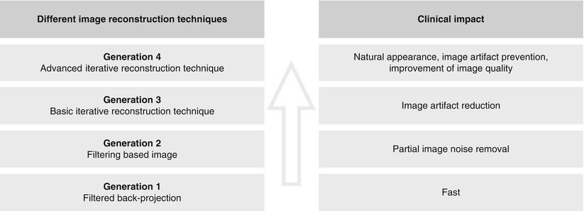
Fig. 1.4
Clinical impact of different image reconstruction techniques
Types of Computed Tomography
Conventional CT
In the early 70s, Electrical and Musical Industries Ltd. (EMI), a company based in London, built the first conventional CT scanner, designed to obtain images of the head. Its prototype was installed in the Atkinson Morley’s Hospital, also in London, where on October 1st 1971 the first tomographic image with clinical ends was taken on a patient with suspicions of a frontal tumor [1, 2]. The EMI Mk1 took between 4.5 and 20 min to take each image, with a matrix of 80 × 80 pixels and a 3 mm × 3 mm × 13 mm voxel size. The processing of the images obtained during the day was carried out in the same factory during the night. This stage took approximately 20 min per image, which were returned to the center in the morning. Modifications in the image’s reconstruction algorithms and a rise in the number of detectors per slice permitted its successor, the CT1010, achieve images with a matrix of 160 × 160 or 320 × 320 pixels, on a field of vision of 210 mm and with an acquisition time of 1 min. The first images of the abdomen obtained on a prototype machine dedicated to body tomography, the CT5000, were achieved only in December of 1974, and Hounsfield himself joined the research team. This CT scanner generated an image with a matrix of 320 × 320 pixels in barely 20 s, and a field of vision of 240, 320, and 400 mm [3].
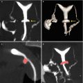
CT scanners from the first and second generations utilized a translation/rotation technology. In the first generation, a thick, collimated pencil X-ray beam faced a detector. Both were then moved covering the object of study, rotated 1°, and moved again and so on until covering a rotation of 180°. During the translation, X-rays are emitted and the data is collected. The resolution of the resulting image is low and the acquisition time very prolonged. In the second generation, the principle to achieve the image is similar; the difference lies in a wider X-rays beam, with a coverage angle of 5°, and a variable number of detectors. This modification permits the acquisition time of data to diminish to a couple of minutes. Another inconvenience with these devices was the instability of the detector, a sodium iodide crystal, and the need to calibrate at the end of each translation, which limited the scanning speed. The CT scanners of third and fourth generation appeared in 1976. The third generation systems are based on a rotation/rotation system, an X-rays beam with a wide coverage width of 30–60°, covering the entire region of study and an arch of detectors composed of multiple elements [3]. In these devices, the X-rays tube and the line of detectors assembled on the gantry turn 360° around the patient. The sweep times are reduced to less than 5 s, along with a better, and less wasteful, use of the radiation. The fourth generation consists of a rotation/stationary system, with a fixed crown of detectors inside of which turns the X-rays tube, reaching high speeds, and thus reducing the scanning time. Plus, the detectors yield a more homogenous result and greater stability (Fig. 1.5).
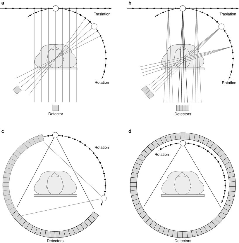
Fig. 1.5
CT systems. (a) First generation. (b) Second generation. (c) Third generation. (d) Fourth generation
Spiral CT
One of the most transcendent and important feats in CT history was the introduction of the spiral (helical) CT in the early 90s. This innovative system of volumetric image acquisition without a doubt constituted the fundamental base for future developments, and put the spotlight on a completely unknown spectrum of new diagnostic applications that generated a rebirth of the method, overshadowed slightly by the growth that magnetic resonance imaging began having around those years [19–24].
Taking into account the better temporal resolution, the image acquisition time lower than 1 s and the possibility of obtaining volumetric information of a certain region, allowed the spiral CT the chance of achieving, for the first time, a volume data without the danger of miss- or double-registration of anatomical details. These third generation CT scanners utilize a slip-ring technology to transmit electrical power for its functioning, disposing of the need for cables in the assembly of the gantry, and are able to achieve a volumetric acquisition of continuous images due to the constant spin of the X-rays tube and the detector system, mounted onto a rotating gantry. The temporal resolution is increased, with acquisition times below 1 s [25–27].
In parallel to the described technological development, an informatics advance of similar magnitude happened, with the appearance of workstations: specially created computers with programmes that offer diverse imaging post-processing techniques to visualize and analyze CT images, such as the multiplanar reformations, the maximum and minimum intensity projections, the three-dimensional surface shaded displays, the volume rendering techniques, and the virtual endoscopy images [28–30].
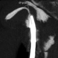
Nevertheless, there were still things to continue working on. The fundamental problem of the spiral CT is the inverse relationship which exists between the acquisition length and the space resolution on the longitudinal axis of the patient. The smallest unit that constitutes the CT image is the voxel. Isotropic images are those which are constituted by voxels, whose x, y and z axis are equal; this is a cubical or isotropic voxel [10]. In the spiral CT, images are constituted by voxels whose length in the x axis are longer in relation to the x and y axis (Fig. 1.6). Although this configuration yields a very good space resolution on the acquisition plane by generating axial images of high anatomical detail, it results insufficient in the creation of multiplanar or three-dimensional reconstructions with a high diagnostic impact. In the spiral CT era, the challenge of achieving isotropic images in a single apnea and large volume coverage were not yet possible. One way to increment the longitudinal resolution and obtain a cubic voxel at the same time is to acquire multiple images simultaneously, using a faster rotation speed of the gantry as well.
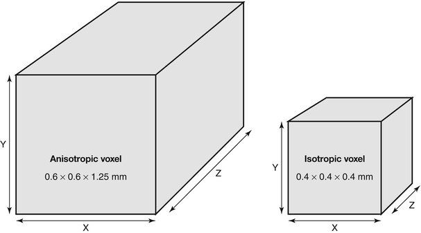
Fig. 1.6


CT voxel configuration
Related posts:
Stay updated, free articles. Join our Telegram channel
Full access? Get Clinical Tree
