Fig. 2.1
A Pro Focus UltraView scanner
Table 2.1
UltraView specifications
Imaging modes: B, M, color Doppler, power Doppler, pulsed wave Doppler, tissue harmonic, contrast imaging |
Features and options: vector flow imaging (VFI), 3D professional, 360° probe support, DICOM, HistoScanning™, remote control, 3 array connectors |
Display: 19″ LCD flat monitor |
Dimensions (approx): system height, 1,475–1,565 mm/58–62 in.; width, 525 mm/21 in.; depth, 765 mm/30 in. |
Weight: 70 kg/154 lb |
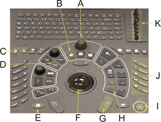
Fig. 2.2
The Pro Focus UltraView 2202 console. A: The general toggle control which amplifies or mutes the signal all across the screen. B: The most important button. Once your machine has your desired setting, the 3D button starts and stops scanning. C: For ID input and probe selection, D: for color Doppler, E: save button saves a video clip of specified duration or if the screen is frozen, an image is captured. F: Your mouse, G: the mouse click, H: for distance measurements, I: freeze button, J: buttons used for changing the depth of scanning, frequency, width, resolution, and range, K: the toggle buttons control selective amplification or muting of signals on the screen © SHOBEIRI 2013
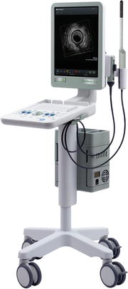
Fig. 2.3
A Flex Focus machine
Table 2.2
Flex Focus specifications
Imaging modes: B, M, color Doppler, PW Doppler, tissue harmonic |
Features and options: 3D 360° probe, DICOM, BK power pack |
Display: 19″ LCD flat monitor |
Dimensions (approx): system height, 1,350–1,602 mm/53–63 in.; keyboard height, 745–1,055 mm/29–41.5 in.; body width, 350 mm/14 in.; depth, 610 mm/24 in. |
Weight: 49 kg/108 lb (excluding probes and printer), 7 kg/15 lb (imaging unit only) |
2.2.1 The 2D Probes
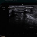
Although any available 2–8 MHz abdominal probe can be used for scanning of the pelvic floor, the images in this book are from a BK 8802 probe unless specified otherwise (Fig. 2.4, Table 2.3).
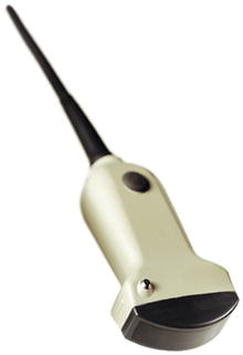
Fig. 2.4
8802 probe
Table 2.3
8802 probe specifications
8802 specifications | |
|---|---|
Frequency range | 4.3–6.0 MHz |
Focal range (typical) | 6–114 mm |
Contact surface | 52 × 8 mm |
Disinfection | Immersion, sterile covers are available |
Physical data (length × width) | 100 × 60 mm |
Weight (approx) | 150 g (approx) |
2.2.2 The 3D Endocavitary High-Resolution Probes
High-resolution 3D allows the automatic acquisition and construction of high-resolution data volumes by synthesis of a high number of parallel transaxial or radial 2D images, ensuring that true dimensions in all three x, y, and z planes are equivalent. The constructed data cube technique provides accurate distance, area, angle, and volume measurements. The volume rendering technique resulting from high-resolution 3D provides accurate visualization of the deeper structures. High-resolution endovaginal or endoanal anatomy can be obtained in 30–60 s. The scanned data set is also highly reproducible, with limited operator dependency. The probe can visualize all rectal wall layers; evaluate the radial, longitudinal extension of sphincter tears; and measure detailed pelvic floor architecture in all x, y, and z planes accurately (Fig. 2.5).
Fig. 2.5
x, y, z planes
2052 Endocavitary 360° Probe
The 2052 probe (Table 2.4, Fig. 2.6) has an internal automated motorized system that allows an acquisition of 300 aligned transaxial 2D images over a distance of 60 mm every 0.2 mm in 60 s, without any movement of the probe within the cavity (Fig. 2.7). The probe has buttons on the handle that allows manual control of the probe (Fig. 2.8). The set of 2D images is instantaneously reconstructed into a high-resolution 3D image for real-time manipulation and volume rendering. The 3D volume can also be archived for offline analysis on the ultrasonographic system or on PC with the help of dedicated 3D Viewer software. The main limitation of this probe is the total length of the probe of 54 cm. Although the probe is also used by colorectal surgeons for staging of rectal tumors which necessitates the length, in pelvic floor imaging, the length may create anxiety for the patients. For pelvic floor imaging, the length requires keeping the hand in a stable position to avoid image distortion. From the methodological point of view, mechanical character of the probe does not allow to obtain the same resolution in all sections, only the axial section (the section of acquisition) has the best quality, and all other sections coming from post-processing of the 3D volume data set have lower resolution.
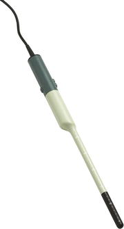
Table 2.4
2052 endocavitary 360° probe specifications
2052 specifications | |
|---|---|
Frequency range | 6–16 MHz |
Focal range (typical) | Up to 50 mm |
Sector angle | 360° |
Disinfection | Immersion |
Physical data | Length: 542 mm |
Shaft length: 270 mm | |
Handle width: 38.4 mm | |
Shaft width: 17 mm | |
Weight (approx) | 850 g (approx) |
Fig. 2.6
2052 probe
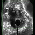
Fig. 2.7
2052 probe creates parallel axial images that are packaged to create a 3D volume
Fig. 2.8
The 2052 probe has two buttons on the handle anteriorly that allows manual pilot of the scanner elements within the probe. The button posteriorly activates the probe or freezes the image on the screen
8848 Endocavitary Biplane Probe
Broad views of anterior and posterior compartments for functional and anatomical studies may be obtained using the 8848 probe (Table 2.5, Fig. 2.9). To obtain quick views of the anterior and posterior compartments, this probe can be rotated manually, but to obtain reproducible 180° 3D measurements, the 8848 probe can be installed on an external mover (Fig. 2.10). The probe has two buttons on the handle that allows for selection of axial or sagittal scanning. It provides detailed high-resolution biplane with 6.5 cm linear and convex views. One can obtain 3D volumes by manually rotating hand 180° when in sagittal mode or withdrawing the hand 6.5 cm when scanning the urethra or the rectum vaginally. However, these 3D volumes are not accurate if measurement of structures is the desired endpoint. To obtain consistent 3D volumes, a 3D mover needs to be utilized.
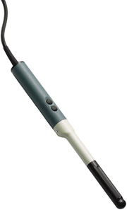
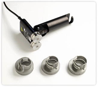
Table 2.5
8848 180° probe specification
8848 specifications | |
|---|---|
Frequency range | 5–12 MHz |
Focal range (typical) | 3–60 mm |
Frame rate/td> | >150 |
Disinfection | Immersion, STERIS SYSTEM 1*, STERIS SYSTEM 1E, STERRAD 50,100S and 200 |
Scanning modes | B,M, Doppler, BCFM, tissue harmonic imaging |
Contact surface (overall) | Transverse: 127 mm2, sagittal: 357 mm2 |
Image field (expanded) | 180°(transverse) |
Weight (approx) | 250 g |
Fig. 2.9
8848 probe
Fig. 2.10
The external mover elements for 8848 probe
8838 Endocavitary 360° Probe
8838 is similar to 8848 probe, but all the mechanisms are internalized (Table 2.6, Fig. 2.11). The probe is world’s first electronic probe for endovaginal and endoanal imaging with built-in high-resolution 3D capabilities. The probe has built-in linear array which rotates 360° inside the probe. The probe has no need for additional accessories or movers; no moving parts come in contact with the patient. The probe has capability for dynamic 2D (Fig. 2.12) and 3D scanning (Fig. 2.13). The probe has wide frequency range 12–6 MHz, with the same excellent imaging capabilities across all frequencies. Probe has a slim 16 mm (0.6) diameter for more comfortable patient imaging with an easy grip to hold and manipulate. Unlike 2052 probe’s long profile which was designed with staging of colorectal cancers in mind, the 8838 is short and less threatening to the patients.
Table 2.6
8838 endocavitary 360° probe specification
2D frequency (MHz) | 12–6 |
Doppler frequency (MHz) | 7.5–6.5 |
Tissue harmonic imaging frequency (MHz) | 10 |
Contrast imaging frequency (MHz) | 4 |
Image field | 65 mm wide acoustic surface able to rotate 360° |
2D penetration depth (mm) | 82–85 |
Footprint (mm) | 65 × 5.5 |
Fig. 2.11
8838 probe
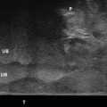
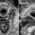
Fig. 2.12
8838 set at scanning at 12:00 o’clock position for dynamic imaging of the bladder
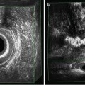
Fig. 2.13
The 8838 probe elements move within the shaft radially to create a 3D data volume
The 8838 probe allows an acquisition of radial 2D images without any movement of the probe within the cavity. The set of 2D images is instantaneously reconstructed into a high-resolution 3D image for real-time manipulation and volume rendering. The 3D volume can also be archived for offline analysis using BK PC software.
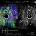
2.2.3 BK 3D Viewer Software
The 3D volume can be used on the scanner, but the ease of use and functionality is better when the free software is installed on any PC (Fig. 2.14). The available functions are lined to the right, bottom, and the left side of the screen. One can scan any patient and export their data files to a CD, DVD, USB, external hard drive, or a server and then view them at any time, on any PC. This is akin to the virtual examination of the patient. The work can be saved and reproduced with ease. On the left side there is an “eye” icon where you can create “memory points.” By clicking on the eye icon, you save the 3D view and find it easily for documentation or research purposes at a later time (Fig. 2.15). Below the “eye icon” is the annotation and arrow icon for writing and marking structures on the 3D volumes (Fig. 2.16). The third icon on the left is the measurement icon. You can obtain linear measurement, angle, area, and volume measurements. When in the measurement mode, additional icons appear on the upper right side that allows to undo or delete all your measurements (Fig. 2.17). The fourth icon on the upper left of the screen is the sculpting icon. One can cut the structures out (Fig. 2.18) or cut the inner structures (Fig. 2.19). Alternately, a structure could be isolated all together (Fig. 2.20). The next 4 icons on the middle left of the screen are for taking snapshots, including the wire frame, removing the personal data, and saving the volumes (Fig. 2.14). On the right side of the screen, there are two icons for adjusting the brightness and the hue. There is also an icon for changing the volume color to soft yellow, blue, or green (Fig. 2.21). On the bottom of the screen, there are icons for opening files, obtaining rendered views (Fig. 2.22). Volume render mode is a technique for the analysis of the information inside 3D volume by digital enhancing individual voxels. It is currently one of the most advanced and computer-intensive rendering algorithm available for computed tomography and can also be applied to high-resolution 3D US data volume. The typical ray-/beam-tracing algorithm sends a ray/beam from each point (pixel) of the viewing screen through the 3D space rendered. The beam passing through the volume data reaches the different elements (voxels) in the data set. Depending on the various render mode settings, the data from each voxel may be stored as a referral for the next voxel and further used in a filtering calculation, may be discarded, or may modify the existing value of the beam. The final displayed pixel color is computed from the color, transparency, and reflectivity of all the volumes and surfaces encountered by the beam. The weighted summation of these images produces the volume-rendered view. The render mode is useful for visualization of tapes and meshes that may seem isoechoic due to dense tissue ingrowth. The dark colors appear darker and the light colors appear lighter in rendered mode and anything in between has lesser intensity.

Fig. 2.14
The screen view of BK 3D software. The empty 3D wire frame is seen in the center with control icons all around it © SHOBEIRI 2013
Fig. 2.15
The “eye icon” saves your screen shot and creates a menu of images of interest for future reference © SHOBEIRI 2013
Fig. 2.16
The annotation and arrow icon allows for marking of the structures on the screen © SHOBEIRI 2013
Fig. 2.17
The measurement icon allows very useful functions such as angle, area, linear, or area/volume measurements © SHOBEIRI 2013
Fig. 2.18
 Endovaginal Imaging of Vaginal Implants
 Three-Dimensional Endoanal Ultrasonography of the Anorectal Region
 Endovaginal Urethra and Bladder Imaging
 Emerging Imaging Technologies and Techniques
 3D Endovaginal Imaging of the Anorectal Structures
 Instrumentation and Techniques for Translabial and Transperineal Pelvic Floor Ultrasound


Related posts:
Endovaginal Imaging of Vaginal Implants
Three-Dimensional Endoanal Ultrasonography of the Anorectal Region
Endovaginal Urethra and Bladder Imaging
Emerging Imaging Technologies and Techniques
3D Endovaginal Imaging of the Anorectal Structures
Instrumentation and Techniques for Translabial and Transperineal Pelvic Floor Ultrasound
Stay updated, free articles. Join our Telegram channel
Full access? Get Clinical Tree
