Fig. 6.1
GE RAB4-8-RS 4–8 MHz probe used for 3D transperineal imaging of the pelvic floor. © Shobeiri
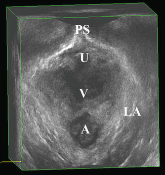
Fig. 6.2
Normal pelvic floor anatomy as seen on 3D transperineal imaging. PS pubic symphysis, U urethra, V vagina, A anus, LA levator ani. © Shobeiri
6.2.2 Endovaginal Imaging
3D EVUS can provide a detailed anatomic depiction of normal posterior compartment structures, and the comparison of these structures to those seen on cadaveric specimens established the basis for the reliable use of this technology in the evaluation of the critical anatomy in this compartment [11]. Additionally, the ARA, which is important in functional assessments, can be visualized and measured [5]. For the beginner sonographer, evaluation of the axial, sagittal, and coronal planes of the rendered 3D volume makes it possible to fully assess the structural and functional anatomy of the anorectum.
Axial Plane
The axial plane allows for visualization of the internal and external anal sphincters. The anal mucosa is visualized at the 6 o’clock position, with the internal anal sphincter creating a hypoechoic ring around the anus. The external anal sphincter can be seen as the more hyperechoic structure surrounding the internal anal sphincter (Fig. 6.3). In 360° imaging with a BK 2052 or 8838 probe, this plane also allows for the evaluation of the levator ani subdivisions, which is discussed in the levator ani imaging chapter. In posterior 3D imaging, important information about the levator plate anatomy can be obtained.
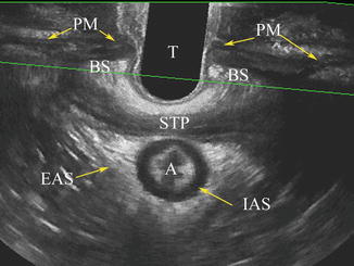
Fig. 6.3
Axial view of the anal sphincter complex as seen on 3D EVUS. T transducer, STP superficial transverse perinea, A anus, EAS external anal sphincter, IAS internal anal sphincter, PM perineal membrane, BS bulbospongiosus muscle. © Shobeiri
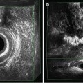
Sagittal Plane
The midsagittal plane gives a longitudinal view of the perineal body, external anal sphincter (main and subcutaneous sections), internal anal sphincter, and RVS (Figs. 6.4, 6.5, and 6.6). The levator plate can also be measured in this plane, allowing for dynamic imaging of this structure both at rest and with Valsalva or squeeze (Figs. 6.7, 6.8, and 6.9). The ARA can also be measured (Fig. 6.10), which may be important in the evaluation of pelvic floor dyssynergy [5, 12].
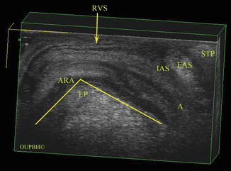
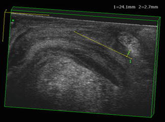
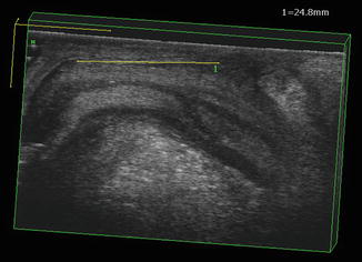
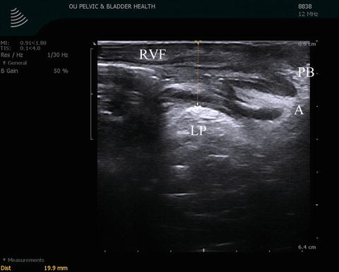
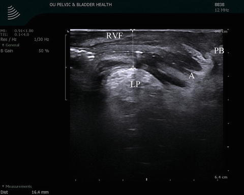
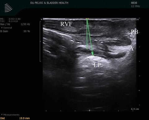
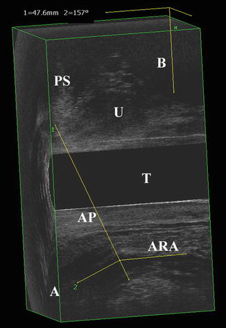
Fig. 6.4
3D EVUS image of the posterior compartment in the midsagittal plane in a patient with normal anatomy. A anus, RVS rectovaginal septum, LP levator plate, IAS internal anal sphincter, EAS external anal sphincter, STP superficial transverse perinea, ARA anorectal angle. © Shobeiri
Fig. 6.5
3D EVUS image of the posterior compartment in the midsagittal plane in a patient with normal anatomy. The internal anal sphincter measurements (length and width) are shown. © Shobeiri
Fig. 6.6
3D EVUS image of the posterior compartment in the midsagittal plane in a patient with normal anatomy. The rectovaginal septum length is shown. © Shobeiri
Fig. 6.7
Normal levator plate as visualized in the midsagittal plane in 3D EVUS imaging. In this image, the patient is at rest with the transducer in the vagina in a neutral position. LP levator plate, PB perineal body, A anus, RVF rectovaginal fascia. © Shobeiri
Fig. 6.8
Normal levator plate as visualized in the midsagittal plane in 3D EVUS imaging. Here, the patient has been asked to squeeze her pelvic floor. LP levator plate, PB perineal body, A anus, RVF rectovaginal fascia. © Shobeiri
Fig. 6.9
Normal levator plate as visualized in the midsagittal plane in 3D EVUS imaging. During imaging, the patient is performing a Valsalva maneuver. LP levator plate, PB perineal body, A anus, RVF rectovaginal fascia. © Shobeiri
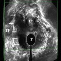
Fig. 6.10
3D EVUS image of the posterior compartment in the midsagittal plane in a patient with normal anatomy. The anorectal angle is measured as shown. PS pubic symphysis, U urethra, T transducer, A anus, ARA anorectal angle, AP anteroposterior line of minimal levator hiatus. © Shobeiri
Coronal Plane
The coronal plane allows the visualization and measurement of both internal and external anal sphincter thickness (Fig. 6.11a, b). This view also allows visualization of the intricate LAM anatomy which creates a collection funnel to allow for passage of bowel contents.
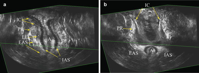
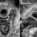
Fig. 6.11
(a) Midcoronal of view of the anal canal (b) demonstrating the role of the levator ani muscles in funneling of the anorectum. Iliococcygeus (IC) creates the collection area, pouborectalis (PR) the neck, longitudinal ligament (LL) the body, and the internal anal sphincter (IAS)/external anal sphincter (EAS) the outlet of the funnel. (2) a more anterior view of the funnel demonstrates overlapping relationship of PR to sheeth like structure of IC. © Shobeiri
6.3 Techniques and Literature Review
6.3.1 Translabial Ultrasound
The posterior compartment imaging always starts with translabial 2D imaging of the posterior compartment. Translabial ultrasound examinations should be performed with the patient in the dorsal lithotomy position, with hips flexed and abducted. A convex transducer is positioned on the perineum between the mons pubis and anal margin (Fig. 6.12). We use a BK 3D convex 8802 frequency 4.3–6 MHz probe with a focal range of 6–114 mm (Fig. 6.13) as further described in the instrumentations and techniques chapter. However, it is possible to use any curved-array transducer with frequencies of 3.5–8 MHz [13, 14]. These probes are readily available in any urologist’s or gynecologist’s office and offer a good introduction to dynamic pelvic floor imaging. Depending on the setting of the machine, the image may be upside down on the machine, and most machines have the capability to display the image as if the patient is standing with the left sagittal plane in view (Fig. 6.13). The transducer is covered with ultrasound gel and covered with a glove, a plastic wrap, or a cover. The pubic symphysis will be on the bottom right of the screen and the levator plate should be visualized on the lower left. During the examination, dynamic imaging is obtained by asking the patient to perform a Valsalva maneuver. It is important, when performing TLUS or TPUS, to avoid excessive pressure on the perineum or inappropriate angle of the transducer (and thus the ultrasound beam) to the anal canal. For more information on transperineal imaging, please refer to the chapter dedicated to this topic.
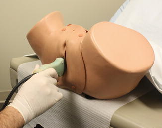
Fig. 6.12
Appropriate positioning of the BK 3D convex 8802 transducer in transperineal imaging. © Shobeiri
Fig. 6.13
BK 3D convex 8802 transducer. © Shobeiri
Clinical Applications
Rectocele. Although many clinicians use the term “rectocele” to refer to any prolapse of the posterior vaginal wall, regardless of underlying anatomic considerations, a true rectocele is defined as herniation of the anterior rectal wall into the vagina and is typically seen during defecation [14]. It is thought to result from a defect in the RVS, although this has not been consistently demonstrated in the literature [15]. Defecography is considered the gold standard imaging technique for evaluation of true rectocele [16], but TPUS has been demonstrated to be an acceptable alternative in the evaluation of true rectocele as well as enterocele and rectal intussusception [5, 6].
By obtaining transperineal images in the midsagittal plane and asking the patient to perform a Valsalva maneuver, one is capable of actively visualizing the downward displacement of the rectum. Its extent can be measured as the maximal depth of protrusion on Valsalva beyond the inferior symphyseal margin (Fig. 6.14). A descent of greater than 10 mm is considered diagnostic of rectocele on ultrasound imaging [5]. However, to date, no studies have demonstrated an association between extent of prolapse and clinical symptoms [17–19].
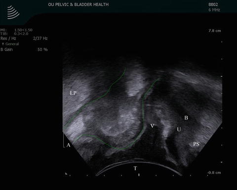
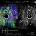
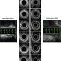
Fig. 6.14
3D TPUS image of a rectocele (outlined in green). On POP-Q examination, this rectocele was identified as a stage 2 rectocele. LP levator plate, A anus, V vagina, B bladder, U urethra, PS pubic symphysis. © Shobeiri
Enterocele. An enterocele is a hernia of the most inferior point of the abdominal cavity into the vagina or rectovaginal space (pouch of Douglas) and typically contains small bowel or sigmoid colon. It is often indistinguishable from rectocele on clinical examination [20]. However, it is important to distinguish between the two when planning surgical intervention. As with a true rectocele, defecography has classically been the imaging modality of choice. However, TPUS may be used as an alternative imaging technique [21].
On TPUS, it is possible to visualize the displacement of small bowel into the vagina with Valsalva (Fig. 6.15). Peristalsis is often seen in the enterocele, and hyperechoic stool which is typical of a rectocele or a sigmoidocele is not visualized. If there is stool present, we call the herniation a sigmoidocele. The differentiation between an enterocele and sigmoidocele is important as redundant sigmoid colon will continue to cause defecatory dysfunction even after repair of the prolapse. The role of levator ani muscles in pathogenesis of prolapse can be easily seen during functional 2D transperineal imaging. A patient with a stage 2 prolapse can easily reduce her prolapse by recruitment of her levator ani muscles (Fig. 6.16).
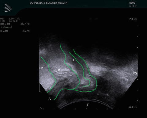
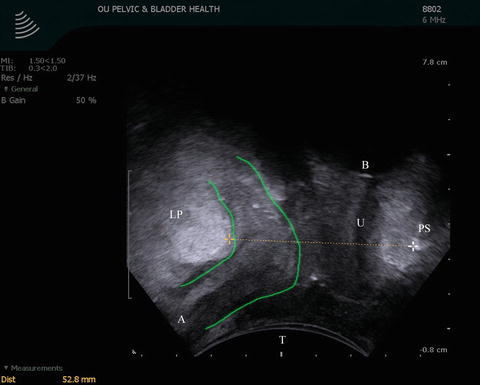
Fig. 6.15
3D TPUS image of a rectocele and enterocele (outlined in green). This image was captured while the patient was asked to perform a Valsalva maneuver. LP levator plate, E enterocele, R rectocele, A anus, T transducer, PS pubic symphysis. © Shobeiri
Fig. 6.16
 Endovaginal Imaging of Vaginal Implants
 Three-Dimensional Endoanal Ultrasonography of the Anorectal Region
 Endovaginal Urethra and Bladder Imaging
 Emerging Imaging Technologies and Techniques
 Instrumentation and Techniques for Translabial and Transperineal Pelvic Floor Ultrasound
 2D/3D Endovaginal and Endoanal Instrumentation and Techniques


Related posts:
Endovaginal Imaging of Vaginal Implants
Three-Dimensional Endoanal Ultrasonography of the Anorectal Region
Endovaginal Urethra and Bladder Imaging
Emerging Imaging Technologies and Techniques
Instrumentation and Techniques for Translabial and Transperineal Pelvic Floor Ultrasound
2D/3D Endovaginal and Endoanal Instrumentation and Techniques
Stay updated, free articles. Join our Telegram channel
Full access? Get Clinical Tree
