Fig. 3.1
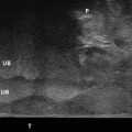
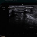
This view demonstrates CORRECT positioning as the starting 2D field of view includes the pubic symphysis (S) anteriorly and the levator plate (LP) posteriorly. Also noted are the bladder (B), uterus (U), vagina (V), anorectum (R) © SHOBEIRI 2013
Many patients may not know what you mean or what to do. So, you have to be specific finding phrases that are familiar to the patient such as please do a kegal or pretend you are holding your urine. This maneuver shows if the patient is discoordinated. Generally, a normal patient has a strong resting tone and the levator lifts slightly vs. a patient who has weak pelvic floor can move the levator plate to a longer distance but cannot reach normal woman’s resting position (Fig. 3.2). (2) The patient is asked to perform Valsalva. You can say “bear down as if you are trying to have a bowel movement.” It is important that this is the last thing you would ask the patient to do since if she has gas in the upper rectum, it may move down and obscure the 3D images you mean to obtain. If this happens you can ask the patient to perform Valsalva again and the gas and prolapse may move up cephalic. Much important information may be obtained with Valsalva. Rectocele (Fig. 3.3), enterocele or most commonly sigmoidocele (Fig. 3.4), cystocele (Fig. 3.5) or multicompartmental defects may come to view with Valsalva maneuver. Dynamic imaging with Valsalva shows the movement of slings and meshes and may show the point of defects above, below or lateral to the mesh (Figs. 3.6 and 3.7). More about this is discussed in chapter about imaging of meshes.
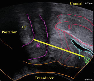
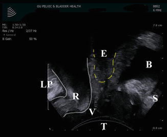
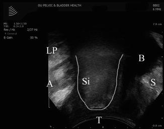
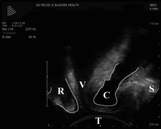
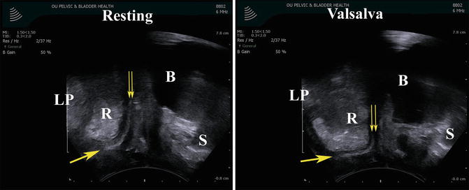
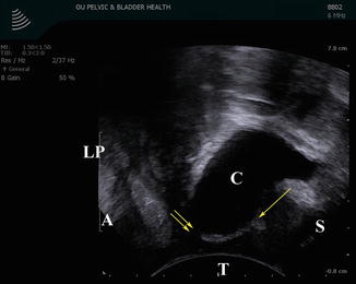
Fig. 3.2
The distance between the pubic symphysis and the levator plate (the yellow line) can be measured in resting, squeeze, and Valsalva position. In 2D images a pelvic floor muscle contraction can be quantified using displacement of the bladder neck, as well as a reduction of the midsagittal diameter (antero—posterior, AP) of the levator hiatus at the level of minimal hiatal dimensions © SHOBEIRI 2013
Fig. 3.3
Translabial imaging with Valsalva in this patient demonstrates a low rectocele (R). The bladder (B) does not demonstrate prolapse, however the shadow of an apical enterocele (E) is seen. Also noted are: the levator plate (LP), vagina (V), the transducer (T), and the pubic symphysis (S) © SHOBEIRI 2013
Fig. 3.4
Translabial imaging with Valsalva in this patient demonstrates a sigmoidocele (Si). Also noted are: the levator plate (LP), anus (A), bladder (B), vagina (V), the transducer (T), and the pubic symphysis (S) © SHOBEIRI 2013
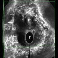
Fig. 3.5
Translabial imaging with Valsalva in this patient demonstrates a concomitant cystocele (C) and a rectocele (R). Also noted are: vagina (V), the transducer (T), and the pubic symphysis (S) © SHOBEIRI 2013
Fig. 3.6
Translabial imaging of a patient with anterior and posterior vaginal mesh. The anterior mesh cannot be seen as clearly. The image to the left is at rest. The double arrows point to the cephalad end of the mesh, and the single arrow points to the caudad end of the mesh. A resting rectocele (R) is seen behind the mesh. The image to the right is with Valsalva. With Valsalva the patient demonstrates worsening of the rectocele and detachment of the apical part of the mesh. Also noted are: the levator plate (LP), bladder (B), the transducer (T), and the pubic symphysis (S) © SHOBEIRI 2013
Fig. 3.7
Translabial imaging of a patient with anterior vaginal mesh. The image is with Valsalva. With Valsalva the patient demonstrates a cystocele (C) and detachment of the apical part of the mesh. The double arrows point to the cephalad end of the mesh, and the single arrow points to the caudad end of the mesh. Also noted are: the levator plate (LP), bladder (B), the transducer (T), and the pubic symphysis (S) © SHOBEIRI 2013
3.2.2 3D/4D Translabial Ultrasonography (TLUS)
Three- and four-dimensional ultrasound has increased public interest in pelvic floor tremendously. The superficial axial plane faces the puborectalis portion of the levator ani, and all the levator subdivisions are better imaged by endocavitary transducers such as BK 2052 or BK 8838. However, endocavitary transducers impede Valsalva maneuver. Although the quality of translabial 3D/4D US are reasonable, the endocavitary transducers used transperineally have much higher resolution and may give better images.
If you have a BK ultrasound machine, the 8802 transducer is capable of free hand acquisition of 3D volumes (Figs. 3.8 and 3.9). However, freehand acquisition with 8802 is only advisable if you do not possess a 2052 or 8838. Performing freehand acquisition of a Translabial 3D volume (1) takes considerable skill to move the transducer at a constant speed as it sweeps radially from the patient’s right to left. (2) The acquired 3D volume is not repeatable or reliable for measurement purposes and most importantly (3) if you have endocavitary 16 MHz transducers at your disposal which obtains automatic high-resolution views of the levator ani muscles, it obviates the need for freehand translabial acquisition.
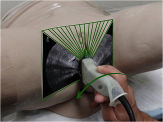
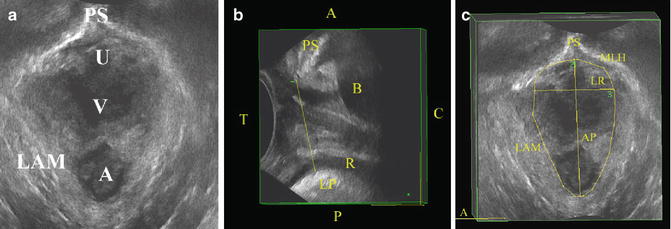
Fig. 3.8
The use of BK 8802 transducer for freehand acquisition of 3D volumes. The transducer is placed between the labia majora and swept at a constant rate from the patient’s left to right. The time during which imaging is obtained can be set. However slower acquisition will result in higher quality 3d volumes © SHOBEIRI 2013
Fig. 3.9
(a) A 3D volume obtained using BK 8802 transducer. The 3D volume can be rotated to look at different areas. (b) Demonstrated is the right sagittal view of the pelvic floor. The anterior-posterior (AP) distance defined as the shortest distance between the pubic symphysis and the levator plate is drawn in a yellow line. The AP line forms the AP line of the minimal levator hiatus (MLH) in (c). Also noted are: the levator plate (LP), bladder (B), the transducer (T), anorectum (R), anterior (A), posterior (P), caudad (C), the left-right line (LR) of the MLH, the levator ani muscle (LAM), and the pubic symphysis (PS or S) © SHOBEIRI 2013
The most commonly published data comes from GE machines. Phillips, Hitachi, and others make similar or superior machines. However, GE’s 4D View is available for offline analysis and use with 4D ultrasound volumes obtained using GE’s Voluson series systems. The cheapest and most easily available system is Voluson e or i (Fig. 3.10). Despite its compact size the system is very capable when used with a RAB4-8-RS transducer (Fig. 3.11). The systems where developed and designed to visualize fetus’ surface structures and adapted for pelvic floor imaging. GE Kretz 4D view allows manipulation of image characteristics and output of stills, cine loops and rotational volumes in bitmap and AVI format. Slightly higher resolutions can be obtained if the endocavitary RIC5-9W-RS is used on the perineum (Fig. 3.12). The characteristics of these transducers are shown in Table 3.1.
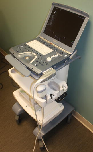
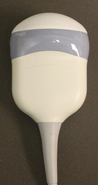
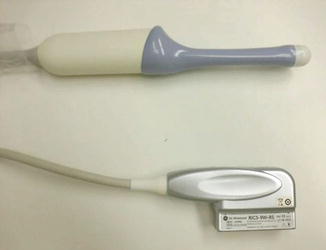
Table 3.1
Characteristics of GE RAB4-8-RS used for translabial ultrasound, and RIC5-9W-RS used for transperineal ultrasound
 ; RAB4-8-RS ; RAB4-8-RS | Real time 4D convex transducer | 63.6 × 37.8 mm | 2–8 MHz | 70°, V 85° × 70° | Voluson i |
Real time 4D endocavity | |||||
 ; RIC5-9W-RS ; RIC5-9W-RS | Next generation real time 4D micro-convex endocavitary transducer, with wide FOV | 22.4 × 22.6 mm | 4–9 MHz | 146°, V 146° × 120° | Voluson i |
Fig. 3.10
A GE Voluson e ultrasound machine © SHOBEIRI 2013
Fig. 3.11
A GE RAB4-8-RS transducer © SHOBEIRI 2013
Fig. 3.12
A GE RIC5-9W-RS transducer
The GE transducer is placed between labia majora and the 2D image as outlined above is displayed on the screen. Depending on the setting of your machine the image orientation may be different. We place the ultrasound machine to the patient’s left and operate the probe with the left hand (Fig. 3.13) which leaves the right hand available for running the console (Fig. 3.14). Once you have the appropriate 2D view, maximize the angle of acquisition to 75°–85° and proceed with 3D imaging (Fig. 3.15). During or after acquisition of volumes it is possible to process imaging information into slices of predetermined number and spacing, reminiscent of computer tomography. This technique has been termed Tomographic Ultrasound Imaging (TUI) by manufacturers. The combination of true 4D (volume cine loop) capability and TUI allows simultaneous observation of the effect of maneuvers. Using this methodology, the minimal levator hiatus (MLH), defined in the midsagittal plane as the shortest line between the posterior surface of the symphysis pubis and the levator plate as the plane of reference, with 2.5 mm steps recorded from 5 mm below this plane to 12.5 mm above.
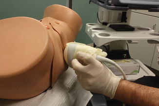
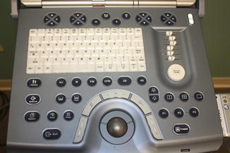
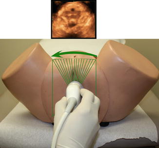
Fig. 3.13
Left-handed application of the transducer during Translabial ultrasonography © SHOBEIRI 2013
Fig. 3.14
The dominant hand generally operated the console. Unlike BK console, the GE Voluson e buttons on the console are multifunctional, and their function corresponds to the menu at the bottom of the screen © SHOBEIRI 2013
Fig. 3.15
3D pelvic floor volume acquisition with GE RAB4-8-RS transducer. The internalized mechanism in the probe moves the crystals obviating the need for hand movement. The hand and the elbow should be rested in a steady position for good quality imaging. The volume obtained is displayed on the screen © SHOBEIRI 2013
3.3 GE 4D View Software
The software is available on the GE machines and also through “Voluson club” for Voluson Ultrasound machine purchaser. Separate licenses for the software are expensive and not available to those who do not have a machine.
3.4 2D/3D/4D Transerineal Ultrasonography (TPUS)
3.4.1 Basic Procedure and Equipment
Ultrasonography has become a common place in Obstetrics, Gynecology, and Urology. Most ultrasound platforms are equipped with curved array and/or endovaginal transducers which are suitable for transperineal ultrasound imaging.
Positioning
As with gynecologic ultrasound most TPUS exams are performed with the woman in either lithotomy in a standard gynecologic examination table or in a modified lithotomy position with cushion placed under buttocks and lower extremities in frog-legged position. For 3-dimensional imaging the examiner may also need to prop their arm or elbow as the imaging capture time can be as long as 15–20 s and the absolute stillness is critical for the optimal image quality. It is certainly possible to do the TPUS with a patient standing, which could be especially useful in patients who are not as successful with dynamic maneuver in supine position.
Transducers and Probes
Transperineal ultrasound refers to ultrasound performed with the transducer position on the perineum. There are techniques described in literature that use translabial ultrasound, i.e., transducer is placed on the labia majora. Term introital ultrasound [10] is also used where transducer is placed at the vaginal introitus or posterior fourchette. The common denominator for all those techniques is placement of transducers externally on the patient’s vulva rather than introduction of the transducer into vagina or anal canal. For the purposes of this chapter we will focus on transperineal ultrasound and mention other types of ultrasound where appropriate for specific studies. TPUS imaging can be performed with use of either trans-abdominal curvilinear transducers or with endovaginal transducer that is typically used for endovaginal gynecologic ultrasound. Curved array transducer is typically 4–8 MHz, whereas endovaginal transducers have frequencies up to 9.0 MHz. It is important to keep in mind that higher frequency transducers provide superior resolution, but have less tissue penetration. This trade-off is important for achieving images of diagnostic quality. For the purposes of this chapter, ultrasound performed with curved array transducers will be referred to as translabial ultrasound (TLUS) as the transducer is placed over the labia majora to visualize anatomic structures. With use of endovaginal transducer the transducer is mostly placed on the perineum or at the posterior fourchette and thus we will refer to it as transperineal ultrasound (TPUS). There is no agreement in nomenclature for these techniques.
Preparation
For transperineal ultrasound as with any ultrasound imaging use of coupling gel is a critical step as ultrasound waves do not pass through air. Whether trans-abdominal or endovaginal transducers are used the gel should be placed between the transducer and covering. For endovaginal transducers a disposable cover (e.g., male condom) and for curved trans-abdominal transducer glove or plastic wrap can be used. Additionally gel should be applied to the perineum to allow for better coupling. Warming the gel in a commercial warming device improves patient comfort. After each use, transducers should be cleaned and disinfected according to manufacturer recommendations.
3.4.2 Transperineal Ultrasound Orientation and Optimization
2D: Technique—Orientation
Different techniques have been described for transperineal and translabial pelvic floor imaging. Some investigators use a curved array transducer (4–8 MHz abdominal probe) [11–13]. The transducer oriented vertically with a mark (i. e., a groove or ridge on one side of the ultrasound transducer) facing up and placed firmly against symphysis pubis. The transducer can be placed on the labia or with labia parted. With the transperineal technique an endovaginal transducer is placed on the perineum with a mark facing up. In this chapter all the TPUS images are captured with endovaginal transducer. The image optimization depends on the goal of desired visualization. With imaging of the pelvic floor muscles and levator hiatus the transducer is directed cranially (Fig. 3.16a, b) with imaging of the anorectum the transducer is usually oriented posteriorly towards the anal canal [14] (Fig. 3.17a, b). Care should be taken to avoid excessive pressure applied to the perineal structures. Most investigators advise to assure tissue contact enough to visualize anorectal structures avoiding any excessive pressure on the perineum. Compression of perineum may distort perineal anatomy and limit mobility of the pelvic floor during dynamic maneuvers.
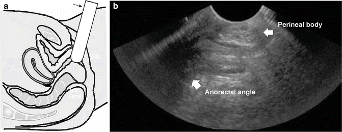
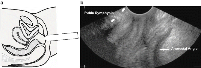
Fig. 3.16
Transperineal ultrasound of the anorectal structures: (a) schematic of endovaginal transducer positioned on the perineum and oriented caudally to visualize anorectum; (b) 2D transperineal sagittal image of the anorectum with perianal body easily visualized as an ovoid structure and anorectal angle marked
Fig. 3.17
Transperineal ultrasound of the pelvic floor hiatus: (a) schematic of endovaginal transducer positioned on the perineum and oriented cranially to visualize the pelvic floor hiatus; (b) 2D transperineal sagittal image of the pelvic floor hiatus with pubic symphysis and anorectal angle shown
In transperineal pelvic floor imaging the transducer is most commonly oriented with the mark facing up (12 o’clock position) with midsagittal orientation. The produced 2D image will represent anterior structures (pubic symphysis and urethra) at the left portion of the screen and the posterior structures (anorectum) at the right side of the screen (Fig. 3.17b). The 2D image produced by TPUS imaging allows for visualization of the urethrovesical junction (UVJ), anorectal angle, structures of the anal sphincter complex. This view can be used to observe pelvic floor mobility during pelvic floor maneuvers, like pelvic floor contraction (Kegel’s exercise) and during straining.
In the midsagittal view the structures seen from left to right: pubic symphysis, urethra and bladder, vagina and anorectum. On the midsagittal view the pubic symphysis cross-section is usually oblong and bony structures of the pubic rami are not visible. Next, anterior and posterior urethral walls are delineated against periurethral tissues. Usually urethral mucosa and submucosa are imaged as a universally hypoechoic structure that appears as an open lumen. Vagina is usually seen as a collapsed structure, where vaginal walls are not clearly separated by ultrasound. Anorectum is seen as outline of hypoechoic internal anal sphincter (IAS) against the midline anal mucosa, which is usually echogenic with variable echogenicity due to fold of anal mucosa. Hyperechoic external sphincter surrounds the hypoechoic internal sphincter. The anorectal angle is normally easily visualized and changes with dynamic maneuvers of the pelvic floor muscles. Cross-section of the puborectalis muscle (PRM) is seen posterior to the anorectal angle.
3D TPUS: Technique
Three-dimensional (3D) ultrasound refers to two-dimensional static display of three-dimensional data. For acquiring and rendering 3D ultrasound dataspecial transducers and software are needed. The 3D ultrasound dataset is referred to as “volume.” To obtain 3D ultrasound the transducer is held in the stationary position at the perineum during acquisition of the volume. The scanning angle is usually set to the widest available—depending on equipment this could be between 120° and 180°. The acquisition time depends on set image quality and varies between 2 and 15 s. The patients are usually instructed to hold her breath (or use shallow breathing) through the volume acquisition phase as any motion can introduce a motion artifact. For the static 3D volume acquisition the quality of acquisition (acquisition time) should be maximized for best quality images. The faster scanning modes usually compromise quality of image but can be useful during dynamic maneuvers. When 3D volumes of dynamic maneuvers are obtained the image quality could be sacrificed for faster acquisition since the subject has to sustain the dynamic state for the length of the acquisition. The dynamic conditions most commonly used for the imaging included pelvic floor contraction and the Valsalva maneuver. When acquiring volumes during the dynamic imaging the position of the transducer at rest may need to be adjusted to allow for the capturing of the dynamic state. The best imaging is achieved by assuring that patients maintain the dynamic state without movement. Any movement from operator or the subject can introduce motion artifact.
3D TPUS: Pelvic floor hiatus—Orientation, Optimization, and Rotation
To capture transperineal 3D US volume of the pelvic floor hiatus and the surround levator ani muscles the transducer placed on the perineum and the ultrasound beam is directed in the cranial direction (Fig. 3.17). The field of view is optimized by identifying the symphysis pubis on the left of the screen and the anal canal on the right side of the screen [15]. The operator should also maximize the midline alignment with assuring that the urethra is also visible in this view. After capturing the volume images can be stored on a compact disk or drive and assessed offline. The offline post possessing is done with equipment-specific software—this is usually proprietary software that allows rotation of the volume, thick and thin slicing of the volume, and multiple measurements. During the post-processing of volumes the 3D static images are rotated to be displayed in a symmetric orientation in the three orthogonal planes: coronal sagittal and transverse planes. A cursor dot is located in corresponding positions in all three orthogonal planes. A cursor dot allows for the exact position of an anatomical structure to be identified simultaneously in the three orthogonal planes (Fig. 3.18). One of the standardized rotation techniques described is demonstrated in the serial figures [15] (Fig. 3.19a–e).
Get Clinical Tree app for offline access
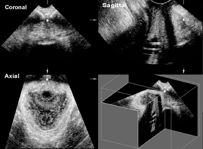
Fig. 3.18
Transperineal static 3D volume processed to demonstrate the relationship of the three orthogonal planes—coronal, sagittal, and axial. The cursor dot seen in each plane represents the exact same spot in each plane
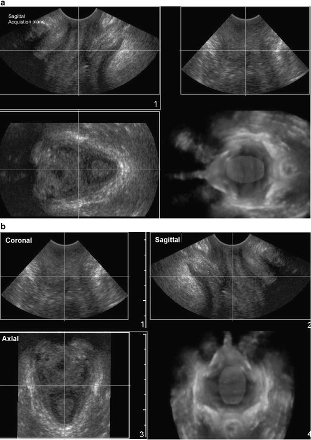
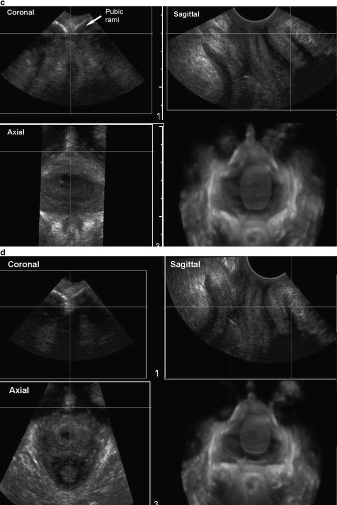
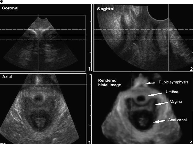
Fig. 3.19
3D TPUS—volume post-processing step-by-step: (a) transperineal ultrasound of the pelvic floor hiatus with the sagittal acquisition plane—sagittal plane optimized by visualizing the pubic symphysis and the anorectal angle; (b) volume is rotated to orient the axial plane upright. The multiplanar of the 3D transperineal volume shown with coronal, sagittal, and axial (transverse) planes identified; (c
 Endovaginal Imaging of Vaginal Implants
 Three-Dimensional Endoanal Ultrasonography of the Anorectal Region
 Endovaginal Urethra and Bladder Imaging
 Emerging Imaging Technologies and Techniques
 3D Endovaginal Imaging of the Anorectal Structures
 2D/3D Endovaginal and Endoanal Instrumentation and Techniques


Related posts:
Endovaginal Imaging of Vaginal Implants
Three-Dimensional Endoanal Ultrasonography of the Anorectal Region
Endovaginal Urethra and Bladder Imaging
Emerging Imaging Technologies and Techniques
3D Endovaginal Imaging of the Anorectal Structures
2D/3D Endovaginal and Endoanal Instrumentation and Techniques
Stay updated, free articles. Join our Telegram channel
Full access? Get Clinical Tree
