Fig. 10.1
Abdominal aorta anatomy
Table 10.1
Abdominal aorta anatomy
Supra-renal tract (yellow) | Celiac artery (1) Superior mesenteric artery (2) Lumbar arteries |
Juxta-renal tract (green) | Right renal arteries (3) Left renal arteries (4) Lumbar arteries |
Infra-renal tract (red) | Inferior mesenteric artery Lumbar arteries |
Table 10.2
Technical parameters using different scanners
4 MDCT | 16 MDCT | 64 MDCT | 128 MDCT | Dual source | |
|---|---|---|---|---|---|
kVp | 120 | 120 | 120 | 120 | 120-120 |
mAs | From 140 to 220 | From 140 to 220 | From 200 to 280 (Dose modulation) | From 200 to 280 (Dose modulation) | From 200 to 280 (Dose modulation) |
Collimation | 4 × 2.5 | 16 × 0.625-1.5 | 64 × 0.6 | 128 × 0.6 | 64 × 0.6 × 2 |
Slice width (mm) | 3-5 | 0.625-2 | 1.25-2 | 0.6-1.5 | 0.6-1.5 |
Recon increment (mm) | 1-2 | 0.625-2 | 0.8-2 | 0.4-1 | 0.4-1 |
Table 10.3
Contrast media administration with different scanners
Cm | 4 MDCT | 16 MDCT | 64 MDCT | 128 MDCT | Dual source |
|---|---|---|---|---|---|
Iodine concentration (mgl/mL) | 350-400 | 350-400 | 350-400 | 350-400 | 350-400 |
Cm volume (mL) | 100-120 | 90-100 | 90-100 | 90-100 | 90-100 |
Saline flush volume (mL) | 50 | 50 | 40 | 40 | 40 |
Delivery rate (mL/s) | 4.0 | 4.0 | 4.0-5.0 | 4.0-5.0 | 4.0-5.0 |
10.2 10.2 CTA Technique
Patient Preparation
Patients should be placed in a supine position on the CT scanner, with the arms behind the head (to reduce beam hardening artifacts).
Image Acquisition
Peripheral venous access should be made in one arm, preferably in the elbow, and must be not less than 20 G. No metal objects should be visible within the field of view.
1)
Topogram acquisition must be on the coronal plane, from the diaphragmatic dome to the proximal portion of the thigh.
2)
The region of interest (ROI) must be placed on the infra-renal abdominal aorta, avoiding intimal calcifications as much as possible (if using bolus tracking), which could alter the diagram of density variation and thus affect the examination.
3)
Image acquisition in the caudocranial direction.
Fundamental points for an optimal angiographic study of the abdominal aorta are:
High contrast media delivery rate (at least 4mL/sec);
High iodine concentration contrast media (350-400 mgl/mL);
Fast image acquisition time
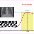
Image acquisition should start right after the threshold value is achieved (120-180 HU); distal vascular segments cannot be opacified by early acquisition. On the other hand, a delayed phase can cause venous and soft tissue contamination.
In older-generation scanners (8-16 detectors), the contrast injection length should be equivalent to the image acquisition time (Tables 10.2–10.3)
10.3 10.3 MRA Technique
This section will examine steady-state free precession sequences (SSFP), Gradientecho T1 3D sequences (GRE), and time–resolved sequences.
Patient Preparation
Patients should be placed in a supine position on the CT scanner, with the arms behind the head; peripheral venous access should be made in one arm, preferably in the elbow, and must be not less than 20 G. No metal objects should be visible within the field of view. Phased array coils for the abdomen and pelvis are necessary.
Table 10.4
Technical parameters
TR (msec) | 4 |
TE (msec) | 2 |
FoV (mm) | 315 × 315 |
Slice width (mm) | 3 |
Matrix | 256 × 256 |
Acquisition time (sec) | 20 |
Steady–State Free Precession sequences (SSFP) are non-contrast bright blood sequences (2D or 3D) (Table 10.4) used in MR imaging in patients with a contraindication or intolerance to paramagnetic contrast media. SSFP uses a low repetition time (RT) and a high flip angle and is used in vascular imaging and for MR enterography.
Arterial and venous systems have the same intensity in SSFP imaging; several applications are used to distinguish one from the other.
Acquisition of a localizer;
FOV placed on the axial or coronal sequence;
FAT and venous saturation.
All sequences are acquired in exhaled breath.
The main limitation is the difficulty in distinguishing between veins and arteries and the strong sensitivity to magnetic susceptible artifacts.
GRE T1 3D
GRE T1 3D are sequences that combine high spatial resolution (high matrix values), low slice thickness (1 mm) and short acquisition times (Fig. 10.2, Table 10.5). As for other bodily applications, it is also necessary for aortic imaging to acquire a pre-contrastographic mask for digital subtraction imaging:
Localizer acquisition;
Pre-contrastographic mask acquisition (GRE) on the coronal plane (Fig. 10.2a);
Real-time contrast media visualization with multiple low-resolution coronal images used as a visual trigger to synchronize image acquisition for optimal timing (Fig. 10.2b-d, Table 10.6);
Post-processing application with digital subtraction imaging (Fig. 10.2). All sequences are acquired in exhaled breath.
Time-Resolved Sequences
Time-resolved imaging is based on the examination of a vascular segment (in this case the abdominal aorta) repeated several times in single time lapse, with real-time visualization of the contrast media (Table 10.7).
Localizer acquisition;
Pre-contrastographic mask acquisition on the coronal plane;
Concurrent contrast media administration and imaging acquisition (Table 10.7);
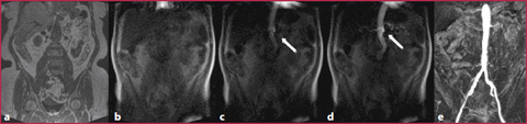
Fig. 10.2
a GRE T1 non-Contrast mask. b-d Real-time visualization of constract media (arrow). e GRE T1 post-contrastographic sequence with digital mask subtraction
Table 10.5
Technical parameters
TR (msec) | 3 |
TE (msec) | 1 |
FoV (mm) | 450 × 450 |
Slice width (mm) | 1.5 |
Matrix | 450 × 270 |
Acquisition time (sec) | 20 |
Table 10.6
Contrast media
CM concentration | 0.5 M |
CM volume (mL) | 15 (0.2 mL/kg) |
Saline flush volume (mL) | 20 |
Delivery rate (mL/s) | 1.5-2 |
Table 10.7
Technical parameters
TR (msec) | 2-5 |
TE (msec) | 1-2 |
Flip angle | 20-50 |
10.4 10.4 Abdominal Aortic Aneurysm
Clinical Picture and Diagnosis
The abdominal aorta is considered aneurysmatic if the transverse diameter is > 3-3.5 cm; its prevalence in the population aged > 50 years is between 1 and 4% (gradually increasing with age).
Imaging and Reporting
The pre-contrastographic phase can provide additional information, which is necessary for adequate pre-surgical planning, such as thrombus calcification or the crescent sign (a hyperdense crescent image in the aneurysmal sac, which is predictive of an upcoming rupture).
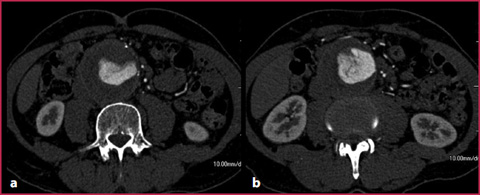
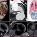
With a standard examination technique, the flow turbulence in the aneurysmatic sac can produce irregular opacification of the vascular lumen (Fig. 10.3); this problem can be resolved by applying a small delay in the acquisition threshold or positioning the ROI directly in the aneurysmatic sac.
Localization
Abdominal aortic aneurysms can be classified as (Fig. 10.4):


1)
Supra–renal: evaluating whether the dilatation involves the aortic thoracic tract;
2)
Juxta–renal: the aneurysm originates at the same level as the renal arteries; it is necessary to evaluate potential renal involvement, by analyzing vascular segments and parenchymal perfusion (pay attention to the supernumerary arteries);
3)
Infra–renal: these are the most common aneurysms, which originate > 1cm below the renal artery.
Fig. 10.3
Abdominal aortic aneurysm with internal blood flow turbulence
Related posts:
Stay updated, free articles. Join our Telegram channel
Full access? Get Clinical Tree
