Fig. 1
Mediastinal lymph node station atlas (taken from Chapet et al., 2005)
Table 1
Description of mediastinal lymph node levels based on anatomical boundaries (permission pending) (Chapet et al. 2005)
Station | Description |
|---|---|
1R: Highest mediastinal nodes | Nodes lying above horizontal line at upper rim of bracheocephalic (left innominate) vein where it ascends to left, crossing in front of trachea at its midline |
2R and 2L: Upper paratracheal nod | Nodes lying above horizontal line drawn tangential to upper margin of aortic arch and below inferior boundary of station 1 nodes |
3: Prevascular nodes and retrotracheal nod | Prevascular and retrotracheal nodes may be designed 3A and 3P; midline nodes are considered to be ipsilateral |
4R and 4L: Right and left lower paratracheal nodes | Lower paratracheal nodes on right lie to right of midline of trachea between horizontal line drawn tangential to upper margin of aortic arch and line extending across right main bronchus, and contained within mediastinal pleural envelope; lower paratracheal nodes on left lie to left of midline of trachea between horizontal line drawn tangential to upper margin of aortic arch and line extending across left main bronchus at level of upper margin of left upper lobe bronchus, medial to ligamentum arteriosum and contained within mediastinal pleural envelope |
5: Subaortic (aortic–pulmonary window) | Subaortic nodes are lateral to ligamentum arteriosum or aorta or left pulmonary artery and proximal to first branch of left pulmonary artery and lie within mediastinum pleural envelope |
6: Paraaortic nodes | Nodes lying anterior and lateral to ascending aorta and aortic arch or innominate artery beneath line tangential to upper margin of aortic arch |
7: Subcarinal nodes | Nodes lying caudal to carina of trachea but not associated with lower lobe bronchi or arteries within lung |
8: Paraeosphageal nodes | Nodes lying adjacent to wall of esophagus and to right or left of midline, excluding subcarinal nodes |
10: Hilar nodes | Proximal lobar nodes, distal to mediastinal pleural reflection and nodes adjacent to bronchus intermedius on right; radiographically, hilar shadow may be created by enlargement of both hilar and interlobar nodes |
11: Interlobar nodes | Nodes lying between lobar bronchi |
The pattern of spread for a primary lung malignancy is typically through the regional lymph nodes (levels N1–N3) and then distantly, with the most common distant sites being the brain, adrenal gland, bone, contralateral lung, liver, and pericardium. However, almost any organ can be potentially involved with disease, and many tumors spread distantly without first demonstrating evidence of regional involvement.
2 Diagnostic Workup Relevant for Target Volume Delineation
SABR
SABR is primarily utilized for stage T1–T2, node-negative tumors.
The goal of the workup for early-stage lesions treated with SABR is thus to rule out locally advanced or metastatic disease. This staging approach therefore includes computed tomography (CT) scan of the chest and positron emission tomography (PET)/CT study. Magnetic resonance imaging (MRI) of the brain is also recommended for patients with T2 disease or higher. Mediastinal evaluation should be considered in all patients, particularly those with stage T2 disease or higher or in centrally located lesions.
PORT
Postoperative radiation therapy is indicated in the following circumstances:
R1 and R2 resections.
N2 or N3 lymph node positivity, diagnosed prior to surgical resection or histologically from the surgical specimen.
Prior studies have also supported the use of PORT in the following circumstances: close margins, extracapsular extension, multiple N1 positivity, a high ratio of positive lymph nodes to resected lymph nodes, incomplete mediastinal evaluation, and operative assessment indicating a high risk for residual disease (Urban et al. 2013; Osarogiagbon and Yu 2012; Lopez Guerra et al. 2013).
Given these indications for PORT, the following studies should be utilized to aid in target utilization:
Preoperative CT scan of the chest with contrast and PET/CT scan.
Preoperative mediastinal evaluation.
Operative report, to include a) extent of lung resection and mediastinal lymph node dissection, b) description of tumor extent operatively, and c) concern for residual disease and potential placement of clips in those regions.
Pathology report, to include a) margin status and location of positive margins (e.g., bronchial stump, parenchymal margins), b) number and stations of lymph nodes sampled, and c) lymph node stations involved with malignancy.
Postoperative imaging (PET/CT scan or CT scan of the chest). In the immediate postoperative period (2–3 months), increased uptake on PET/CT scan often represents postoperative changes. However, particularly if there is an operative concern for residual disease, postoperative imaging can assist in identifying regions of concern for consideration of a boost dose.
3 Simulation and Daily Localization
SABR
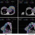
Immobilization – Various immobilization systems are available for SABR. Early SABR used body frame systems that were designed to allow the patient to be imaged in a different room than the treatment was taking place, analogous to the head frame used in SRS. These include the BodyFixTM and Body Pro-LockTM systems which also provided abdominal compression devices. With the advent of in-room CT, modified upper body cradles could be used as final volumetric imaging was now being done in the treatment room. SABR immobilization devices typically provide greater support than those utilized in standard fractionation regimens. Figure 2 demonstrates an example of an upper body cradle utilized for SABR (Fig. 2a) vs. that in conventional fractionation (Fig. 2b).

Fig. 2
Differences between an SABR and non-SABR bag. The SBRT holds an actual impression of the patient and provides more support, is generally longer, and provides an area for fiducial placement. A conventional bag is not adequate for setup or immobilization for SABR
Simulation – CT simulations are performed with a slice thickness of 2.5–3 mm. Four-dimensional (4D) CT scans are acquired, to account for internal motion. Intravenous contrast can be considered when necessary to differentiate tumor involvement from mediastinal structures such as the vasculature, and this should be done on a traditional fast helical CT immediately after the 4DCT without moving the patient. When the magnitude of respiratory motion is less than 1 cm and regular, patients are typically treated with a “free-breathing” approach, in which they breathe regularly during a treatment designed to cover the entire track of the tumor motion. If irregular or motion >1 cm, then respiratory management is considered, either breath hold at deep inspiration or at expiration or free-breathing respiratory gating in which radiation is delivered at specific periods of the breathing cycle. Any gating technique should include daily imaging that can verify the gating level each day. Both breath-hold and free-breathing gating techniques have been shown to be beneficial in reducing target volumes for tumors that have substantial motion (Muirhead et al. 2010; Underberg et al. 2005). Deep inspiration breath hold has been shown to reduce overall lung dose by expanding the healthy lung away from the tumor, but for patients to this, they need to be able to maintain the appropriate position in the respiratory cycle for at least 15 s, which is difficult for a significant percentage of patients with lung cancer. They also need to be able to reproduce the location of the tumor on successive breath holds as verified by repeated breath-hold CTs; this may be added by video feedback or an occlusion value system such as that found in the ABC device.
Daily Localization – Daily volumetric imaging is used during treatment (cone-beam CT scan, CT on rails). The daily imaging must be performed in a way consistent with the delivery method, e.g., free-breathing CBCT for free-breathing patients, breath-hold CT for breath-hold patients, or dynamically gated CT for free-breathing gated patients. If volumetric imaging is not available, then fiducial implants can be placed to provide more accurate localization, though this fiducial placement should be correlated with bony anatomy and with each other daily to assess for interfraction migration.
PORT
Immobilization – Conventional fractionation upper body cradles with arms over the head are utilized (Fig. 2b).
Simulation – CT simulations are performed with a slice thickness of 2.5–3 mm. 4D CT simulations are again recommended, with measurement of target motion and respiratory management if the target motion is >1 cm. The 4D CT scan range typically extends from at least the thoracic inlet to the inferior portion of the diaphragm. This scan should be inclusive of the involved lymph nodes on imaging and histologically.
Daily Localization – Daily kV imaging is typically utilized with consideration of weekly volumetric imaging in a subgroup of patients, to confirm that the bony alignment is concordant with the underlying anatomical target.
4 Target Volume Delineation and Treatment Planning
SABR
Image Fusion – Image fusion with PET/CT scans can be useful for SABR treatments, particularly if there is surrounding atelectasis.
Target Volumes – Gross tumor volume (GTV) with tumor motion taken into account for free-breathing treatments. The motion is taken from the 4DCT for gated treatments, and it is taken from the gated images with a margin for the patient-specific uncertainty in the gating. In this context, the GTV is equivalent to the internal target volume (ITV) (i.e., not enlarged for presumed microscopic extension). The ITV is then expanded to create the planning target volume (PTV). The GTV to PTV expansion is then 0.5 cm. These guidelines are consistent with those described in protocol RTOG 0915.
Stay updated, free articles. Join our Telegram channel

Full access? Get Clinical Tree


