Target volumes
Definition and description
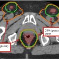
CTV
Breast tissue or chest wall as defined by RTOG Breast Cancer Atlas1, ipsilateral regional lymph nodes2, interconnecting lymphatic drainage routes, and chest wall musculature/skin determined to be at risk for microscopic disease
PTV
A margin of 3–5 mm medially, 5–10 mm laterally, 3–5 mm posteriorly, and 5–10 mm superiorly, inferiorly, and anteriorly (to include the skin surface) will be added to the CTV. The amount of lung can be trimmed per physician discretion

Fig. 1
Coronal view. Red PTV, light orange CTV, blue level I lymph nodes, light purple level II lymph nodes, dark orange level III lymph nodes, green supraclavicular lymph nodes, yellow green internal mammary nodes (IMN)

Fig. 2
Sagittal view. Red PTV, light orange CTV, blue level I lymph nodes, light purple level II lymph nodes, dark orange level III lymph nodes, green supraclavicular lymph nodes, yellow green internal mammary nodes (IMN)

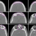
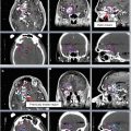
Fig. 3
Axial slices in the cranial to caudal direction

Fig. 4
Coronal view: red PTV, light orange CTV, blue level I lymph nodes, light purple level II lymph nodes, dark orange level III lymph nodes, green supraclavicular lymph nodes, yellow green internal mammary nodes (IMN), yellow heart, dark purple contralateral breast

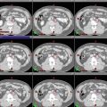
Fig. 5
Axial slices in the cranial to caudal direction


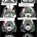
Fig. 6
Axial and coronal slices in the cranial to caudal direction: red PTV; light orange CTV; yellow level I, II, and III and supraclavicular lymph nodes; yellow green internal mammary nodes (IMN); pink contralateral implant; purple the superior border of daily bolus

Fig. 7
Axial view of three beams: a medial en face electron beam (red) matched to two lateral opposing tangent fields (blue and green)

Fig. 8
Coronal view of supraclavicular field and lymph node targets

Fig. 9
3D view of a boost to the tumor bed: An en face electron field with a custom cutout (blue) encompasses the tumor bed (maroon), clips (light green), and lumpectomy scar (gray)

Fig. 10
Daily setup tattoos in a patient receiving multi-beam breast IMRT. A diagram for right breast IMRT patient setup. The medial tattoo (MED TT) is the starting point for isocenter shift

Fig. 11
Align RT for daily setup verification. An example of a breast IMRT patient setup in a patient with left-sided breast cancer, using AlignRT surface images to align with the external contour of simulation CT image as the reference. The solid pink area is the region of interest (ROI) on the CT contour and the green surface is the setup surface image acquired at treatment. The arm, chin, and neck region are aligned well with the ROI surface

Fig. 12
Dose-volume histograms of a conventional RT versus an 8-field IMRT treatment plan

Fig. 13
Axial and sagittal views of isodose lines in a conventional RT versus an 8-field IMRT treatment plan
2 Simulation and Setup Verification
The radiotherapy treatment planning process starts at the time of simulation, where the patient position is set to the anticipated position for treatment planning. The rule of thumb for patient positioning includes (1) easy access by radiation beams without passing through unnecessary normal tissue or causing collision with the gantry, couch, or patient; (2) a comfortable position with an immobilization device that enables the patient to lie still in supine position during treatment; and (3) a reproducible approach with body tattoos, body-couch index, and image guidance to facilitate patient setup at treatments. A three-dimensional (3D) computed tomography (CT) image of a patient at the treatment position will be acquired, which is essential for 3D or intensity-modulated radiotherapy (IMRT) planning (Leibel et al. 2002; Aird and Conway 2002). Additional imaging modalities may be prescribed and acquired to enhance the visualization of a tumor and surrounding normal tissues and to facilitate tumor delineation and localization, including positron emission tomography (PET)/CT, magnetic resonance imaging (MRI), or respiratory-correlated 4DCT images.
At Memorial Sloan Kettering Cancer Center, a simulation for breast IMRT treatment requires that the patient lies in supine position on a breast board (CIVICO Medical Solutions, Kalona, Iowa) or a body mold, with the torso tilted upward with 5°–10° and both arms up. A clinician places wire markers around the breast or implant and on the surgical scar. Patient alignment is checked with scout radiograph images, followed by CT scanning with a field of view from the chin to about 5 cm inferior to the marked breast tissue. It is essential to ensure that the entirety of both lungs is included in the simulation scan, so that a lung DVH (dose-volume histogram) may be subsequently constructed at the treatment planning stage. Patients are scanned in free breathing on a helical CT scanner (BigBore Brilliance, Philips Healthcare, Andover, MA). After the treatment isocenter is localized on the reconstructed CT image, the room laser is used to mark the patient with bi-angulation tattoos at the medial and lateral sides on the supraclavicular line, inferior treatment boarder and midline in between, as shown in Fig. 10. Three tattoos on the supraclavicular match line, two on the midline, and two on inferior boarder. These seven tattoos are used to straighten out the patient body at daily treatment to reproduce the simulation position. An additional tattoo is marked to reflect the lateral shift to the isocenter from the medial tattoo (which is also used to define the superior-inferior (SI) and vertical shifts to the isocenter – the tattoo is indicating the lateral shift only). The source-skin distance (SSD) at the medial tattoo and the isocenter will be checked before and after isocenter shift from the medial tattoo. A simulation document is written and checked by two simulation therapists, including the board tilt, bottom stop position, arm rest indexing, knee support size, as well as the coordinates of the isocenter, which again will be checked by a planner. A detailed setup instruction is also checked by the simulation therapists before releasing to the physics team for IMRT planning.
Related posts:
Stay updated, free articles. Join our Telegram channel

Full access? Get Clinical Tree


