• State the purpose of automatic exposure control (AEC) in radiography. • Differentiate among the types of radiation detectors used in AEC systems. • Recognize how the detector size and configuration affect the response of the AEC device. • Explain how alignment and positioning affect the response of the AEC device. • Discuss patient and exposure technique factors and their effect on the response of the AEC device. • Define anatomically programmed radiography (APR). • Analyze unacceptable images produced using AEC and identify possible causes. • Recognize the effect of the type of image receptor on AEC calibration, its use, and image quality. • Describe patient protection issues associated with AEC. • State the importance of calibration of the AEC system to the type of image receptor used. The difference in AEC systems lies in the type of device used to convert radiation into electricity. Two types of AEC systems have been used: phototimers and ionization chambers. Phototimers represent the first generation of AEC systems used in radiography, and it is from this type of system that the term phototiming has evolved. Phototiming specifically refers to the use of an AEC device that uses photomultiplier tubes or photodiodes, and these systems are not common today. Therefore the use of the term phototiming is usually in error. The more common type of AEC system uses ionization chambers. Regardless of the specific type of AEC system used, almost all systems use a set of three radiation-measuring detectors, arranged in some specific manner (Figure 13-1). The radiographer selects the configuration of these devices, determining which of the three individually or in combination actually measures radiation exposure reaching the image receptor. These devices are variously referred to as sensors, chambers, cells, or detectors. These radiation-measuring devices are referred to here for the remainder of the discussion as detectors. Phototimers use a fluorescent (light-producing) screen and a device that converts the light to electricity. A photomultiplier (PM) tube is an electronic device that converts visible light energy into electrical energy. A photodiode is a solid-state device that performs the same function. Phototimer AEC devices are considered exit-type devices because the detectors are positioned behind the image receptor (Figure 13-2) so that radiation must exit the image receptor before it is measured by the detectors. Light paddles, coated with a fluorescent material, serve as the detectors, and the radiation interacts with the paddles, producing visible light. This light is transmitted to remote PM tubes or photodiodes that convert this light into electricity. The timer is tripped and the radiographic exposure is terminated when a sufficiently large charge has been received. This electrical charge is in proportion to the radiation to which the light paddles have been exposed. Phototimers have largely been replaced with ionization chamber systems. An ionization or ion chamber is a hollow cell that contains air and is connected to the timer circuit via an electrical wire. Ionization-chamber AEC devices are considered entrance-type devices because the detectors are positioned in front of the image receptor (Figure 13-3) so that radiation interacts with the detectors just before interacting with the image receptor. When the ionization chamber is exposed to radiation from a radiographic exposure, the air inside the chamber becomes ionized, creating an electrical charge. This charge travels along the wire to the timer circuit. The timer is tripped and the radiographic exposure is terminated when a sufficiently large charge has been received. This electrical charge is in proportion to the radiation to which the ionization chamber has been exposed. Compared with phototimers, ion chambers are less sophisticated and less accurate, but they are less prone to failure. Most of today’s AEC systems use ionization chambers.
Automatic Exposure Control
Radiation Detectors
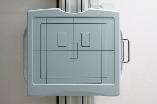
Arrangement of three automatic exposure control detectors on an upright Bucky unit.
Phototimers
Ionization Chamber Systems
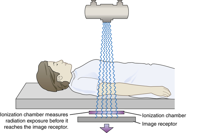
The ionization chamber automatic exposure control system has the detectors located directly in front of the image receptor. This is an entrance-type device because the x-ray exposure is measured just before entering the image receptor.
Radiology Key
Fastest Radiology Insight Engine
 Critical Concept 13-1
 Critical Concept 13-2
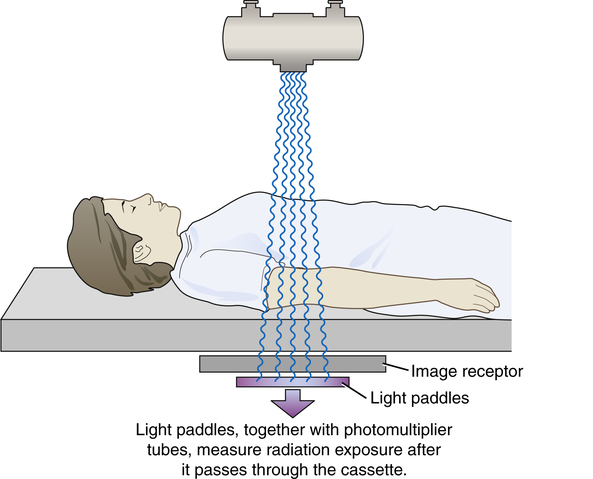
 Critical Concept 13-3
 Critical Concept 13-4
 Critical Concept 13-5
 Critical Concept 13-6