• Describe the principal parts of an image intensifier and their function. • Explain the operation of an automatic brightness control (ABC). • Explain the operation of an image intensifier in magnification mode. • Describe the options for viewing systems and the advantages and disadvantages of each. • Describe the options for recording systems and the advantages and disadvantages of each. • Discuss the fundamental principles of operation of the different approaches to digital fluoroscopy. • Identify the major areas of quality control pertaining to fluoroscopy. • Differentiate between those quality control processes that are the responsibility of the radiographer and those of the medical physicist. Shortly after Dr. Roentgen’s discovery of x-rays and subsequent announcement, many other scientists began experimenting with this new phenomenon. Among them was the famed American inventor Thomas Edison. Among Mr. Edison’s more notable inventions in this area was the first commercially available fluoroscope in 1896, although it was not in a form we would recognize today (Figure 14-1). His fluoroscope was a calcium tungstate screen that interacted with the remnant beam, producing a very faint image that one viewed while standing in the path of the x-ray beam as it exited the patient and screen. The practice of standing in the direct path of the x-ray beam meant that the dose to the fluoroscopist was extremely high. Additionally, because the image was very dim, the fluoroscopist had to “dark-adapt” by sitting in a darkened room for a period or by wearing adaptation goggles with red lenses before performing the fluoroscopic examination. However, fluoroscopy’s great advantage, which ensured its continued development, was that it allowed for dynamic radiographic examination. That is, the inner workings of the human body could be viewed in real time. Conventionally the fluoroscopic chain consists of an x-ray tube, an image intensifier, a recording system, and a viewing system (Figure 14-2). The integration of digital technology is changing parts of this system, as is discussed at the end of this chapter. Here the focus is on the design and function of the image intensifier, recording, and viewing systems. Figure 14-3 illustrates the image intensifier within the fluoroscopic tower. The image intensifier is an electronic vacuum tube that converts the remnant beam to light, then to electrons, then back to light, increasing the light intensity in the process. It consists of five basic parts: the input phosphor, photocathode, electrostatic focusing lenses, accelerating anode, and output phosphor. The input phosphor is made of cesium iodide and is bonded to the curved surface of the tube itself. Cesium iodide absorbs the remnant x-ray photon energy and emits light in response. The photocathode is made of cesium and antimony compounds. These metals emit electrons in response to light stimulus in a process called photoemission. The photocathode is bonded directly to the input phosphor using a very thin adhesive layer. These layers are curved so that all of the electrons emitted from the photocathode travel the same distance to the output phosphor (Figure 14-3). The electrostatic focusing lenses are not really lenses at all, but are negatively charged plates along the length of the image intensifier tube. These negatively charged plates repel the electron stream, focusing it on the small output phosphor. To set the electron stream in motion at a constant velocity, an accelerating anode is located at the neck of the image intensifier near the output phosphor. This accelerating anode maintains a constant potential of approximately 25 kV. The output phosphor is made of silver-activated zinc cadmium sulfide and is much smaller than the input phosphor. It is located at the opposite end of the image intensifier tube, just beyond the accelerating anode. This layer absorbs electrons and emits light in response. Generally, the input phosphors are 15 to 30 cm and the output phosphor is usually 2.5 cm. Another function of some image intensifiers is multifield mode or magnification mode. Most image intensifiers in use today have this capability. When operated in magnification mode, the voltage to the electrostatic focusing lenses is increased. This increase tightens the diameter of the electron stream and the focal point is shifted farther from the output phosphor (Figure 14-4). The effect is that only those electrons from the center area of the input phosphor interact with the output phosphor and contribute to the image, giving the appearance of magnification. For example, a 30/23/15–cm trifocus image intensifier can be operated in any of those three modes. When operated in the 23-cm mode, only the electrons from the center 23 cm of the input phosphor interact with the output phosphor; those about the periphery will miss and not contribute to the image. The same is true of the 15-cm mode. Selecting magnification mode automatically adjusts x-ray beam collimation to match the displayed tissue image and avoids irradiating tissue that does not appear in the image. The degree of magnification (magnification factor [MF]) may be found by dividing the full-size input diameter by the selected input diameter. For example:
Image Intensified Fluoroscopy
Introduction
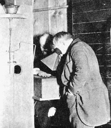
Thomas Edison experimenting with the fluoroscope he designed. The subject is his assistant, Clarence Dally. (From Eisenberg RL: Radiology: an illustrated history, St Louis, 1992, Mosby.)
Construction
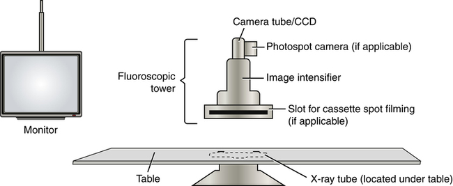
The general components of the fluoroscopic chain. Note that the x-ray tube for the system is typically located under the table.
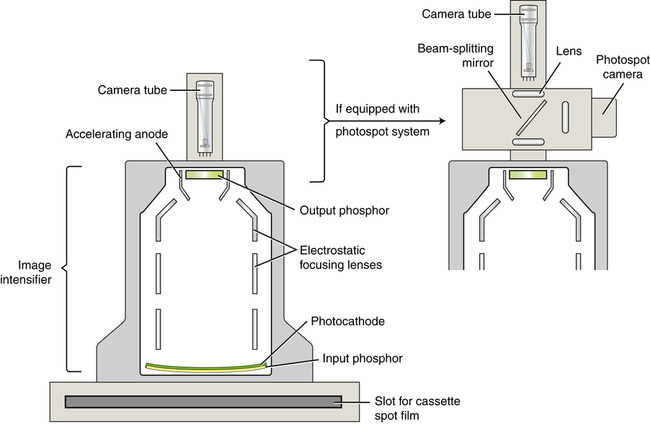
The image intensifier is situated within the fluoroscopic tower and is attached to a camera tube. The method of attachment depends on the image-capture features of the system.
Intensification Principles

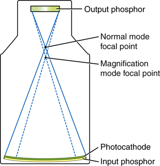
When the image intensifier is operated in magnification mode, the voltage on the electrostatic focusing lenses is increased, narrowing the diameter of the electron stream and shifting the focal point farther from the output phosphor, resulting in a magnified image.
![]()
Stay updated, free articles. Join our Telegram channel

Full access? Get Clinical Tree


Radiology Key
Fastest Radiology Insight Engine
 Critical Concept 14-1
 Critical Concept 14-2
 Critical Concept 14-3