Fig. 1
Automatic exposure control with MDCT. Lateral topogram (scout view) for thoracoabdominal CT in a 6-year-old child. The curve represents the automatically adapted milliampere-seconds value as a function of z-axis position during scanning with spiral CT. Although the standard adult protocol was used, the average milliampere-seconds value throughout the scan was adjusted to 38 mAs with automatic exposure control (Flohr et al. 2005, used with permission)
The benefit of the use of lower tube voltage for pediatric cardiac CT is a higher iodine contrast-to-noise ratio at a given radiation dose (Yu et al. 2011). When we use low tube voltage with tube current modulation, we should recognize that the tube current may be saturated to its maximum level resulting in excessive image noise and adversely affecting the image quality (Goo and Suh 2006b; Israel et al. 2008). The most practical solution to this problem is to use a lower pitch value. Other important measures to decrease radiation dose of pediatric cardiac CT include confining the study to the anatomical area of interest, avoiding multiphase examinations, and using iterative or other noise-reducing reconstruction algorithms (Goo 2012). In the contemporary MDCT era, a greater contribution of unnecessary overranging effect should be seriously considered particularly in CT examinations with a shorter scan range, such as pediatric cardiac CT, (Tzedakis et al. 2007) and volumetric axial scan modes with wide array detector configurations (Kroft et al. 2010) or adaptive section collimation should be used to reduce the overranging if applicable (Deak et al. 2009).
ECG-controlled tube current modulation is a technique available to reduce the radiation dose associated with retrospective gating (Jakobs et al. 2002). In those cardiac phases that are not needed for image reconstruction with high quality, the tube current is reduced to 4–20 % of the initial setting. Cardiac phases demanding the full tube current for high image quality should be appropriately selected according to a patient’s heart rate (Weustink et al. 2008).
By using available dose-reduction strategies simultaneously, the radiation dose of pediatric cardiac CT now can often be reduced to less than 1.0 mSv (Goo 2010a, 2011a).
2.4 Planning Scan Technique and Intravenous Contrast Injection
It is vital for the radiologist performing and interpreting pediatric cardiac CT to review any information pertaining to the child’s form of CHD and surgical repair or palliation prior to scanning. The knowledge helps the radiologist determine scan and intravenous (IV) injection protocols to best visualize anatomic substrates of the child. In addition, the ability of a child to follow breathing instructions is important to determine scan technique. The ultimate goal of IV contrast injection in pediatric cardiac CT is to obtain homogeneous enhancement of cardiovascular structures included in the scan range as much as possible because single-phase scanning should demonstrate all of them clearly to minimize radiation dose. However, homogeneous enhancement on pediatric cardiac CT is not always attainable, particularly in cases with complicated anatomy such as a Fontan pathway (Fig. 2). For optimal enhancement of a Fontan pathway, simultaneous IV injection of 50 % diluted or undiluted contrast agent via upper and lower extremities has shown good results (Greenberg and Bhutta 2008; Prabhu et al. 2009; Goo 2011b). Inhomogeneous cardiovascular enhancement may be contradictorily helpful to demonstrate hemodynamic findings, such as collateral vessels and contrast jet through a defect (Goo 2011c).
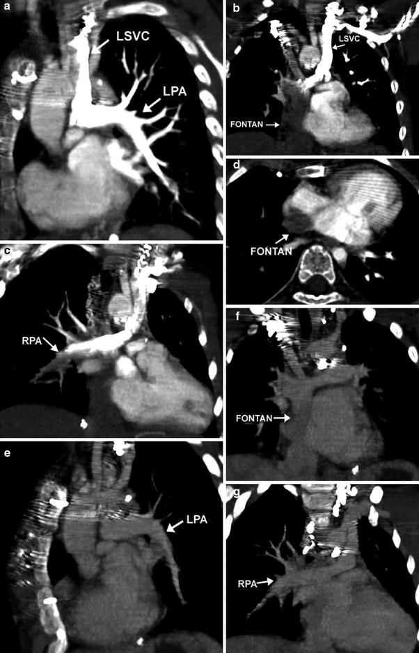
Fig. 2
Lack of opacification of the Fontan pathway during arterial phase of scanning. Coronal and axial oblique MIP images demonstrate dense contrast in the LPA via a left sided SVC after a left arm injection (a). The Fontan pathway from the IVC (b, d) and the distal RPA (c) are incompletely opacified. Coronal oblique images reconstructed from the venous phase demonstrate homogeneous opacification of the LPA (e) Fontan pathway (f), and RPA (g)
IV injection rates in children should necessarily be adjusted depending on the size of the IV catheter able to be placed and the amount of contrast to be injected (usually in the range of 1–2 ml/kg). Table 1 provides a guideline for contrast injection rates by size of the IV catheter. The optimal scan delay from the start of IV injection is usually determined by using bolus tracking. As compared with a biphasic IV injection protocol, a triphasic protocol, in which undiluted contrast agent is followed by 50–60 % diluted contrast agent and then by a saline chaser, can not only provide improved enhancement of the right heart, but also reduce perivenous contrast artifacts (Litmanovich et al. 2008).
Table 1
Maximal intravenous contrast injection rates
Catheter size (g) | Flow rate (cc/s) |
|---|---|
18 | 5–6 |
20 | 4–5 |
22 | 3–4 |
24 | 1–2 |
3 Complementary Role of MDCT and MRI for Cardiac Imaging
The complementary role of MDCT and MRI for noninvasive cardiac imaging in children with CHD should be clearly recognized. Relative merits and demerits of the two imaging modalities are summarized in Table 2. Recent technical developments in pediatric cardiac CT have changed the complementary role between MDCT and MRI to some extent. Although cardiac MRI techniques have also advanced, major limitations of cardiac MRI particularly in young children are still remained to be overcome: limited accessibility to MRI scanners for pediatric cardiovascular examinations in many hospitals and institutions, longer examination time, more requirement of sedation or anesthesia, and technical expertise to perform routine quality examinations. For the initial evaluation of CHD in infants and young children, echocardiography often provides a complete assessment of intracardiac morphology, flow, and ventricular function. However, echocardiography is limited in evaluating extracardiac structures and may not adequately show intracardiac and coronary artery anatomy. Cardiac CT may be helpful to compensate for these blind spots of echocardiography. Consequently, pediatric cardiac CT is increasingly used as a complementary imaging modality in many institutions before and after surgical correction in young children with CHD. On the other hand, cardiac MRI or invasive cardiac catheter angiography is seldom mandatory for surgical planning in these patients.
Table 2
Complementary role of MDCT and MRI for cardiac imaging
MDCT | MR | |
|---|---|---|
Need for sedation | Sedation required in many patients <4 years | Sedation or GA needed in most patients <7 years |
Duration of sedation | Very short | Long |
IV contrast | Risk of allergic reaction, renal dysfunction | Risk of nephrogenic systemic fibrosis |
Spatial resolution | Better. True isotropic resolution | Good. Near isotropic resolution |
Temporal resolution | Good | Better |
Dynamics on angiogram | Multiple dynamics possible, but not preferred in children due to radiation risk | Multiple dynamics routinely performed, with separation of right and left-sided and venous structures |
Flow quantification | Not currently possible | Many applications: stroke volume, Qp:Qs, regurgitant fraction, gradient measurement through stenosis |
Ventricular function | Adequate temporal resolution | Better temporal resolution |
Imaging time | Very short (<1 min) | Long (30–60 min) |
Contraindications | Acute renal failure | Pacemakers, AICD |
Compatibility with coils, stents, and metallic prosthesis | Metal causes artifact, worse with platinum. Best non-invasive means of evaluating stent patency | Unable to assess patency of stents and metallic prostheses due to artifact. Steel coils cause most artifact. Platinum coils cause minimal artifact |
Health risks | Radiation | Over-heating of the body |
Post processing techniques | 3D volume rendering, MIP, MPR | Similar |
Ideal indications | Coronary stenosis imaging, anomalous coronaries, emergent studies like aortic dissection or occluded BT shunt, pulmonary embolism, airway evaluation, need to avoid sedation | Conditions requiring serial studies, screening studies, or conditions requiring evaluation of flow, valvular and ventricular function, and chamber morphology |
As evaluation with echocardiography becomes increasingly more difficult in older and larger patients who have had multiple cardiothoracic surgeries, cardiac MRI is regarded as the noninvasive imaging method of choice for serial follow-up examinations in patients with repaired CHD. Examples include patients with repaired tetralogy of Fallot (TOF), patients with a systemic right ventricle following the Senning or Mustard operation, and functional single ventricle patients following the Fontan operation. Unfortunately, the image quality of cardiac MRI may be considerably compromised by susceptibility artifact from the previously placed embolization coils, stents, and occlusion devices. In addition, indwelling pacemakers and AICD devices remain contraindications for MRI. On these occasions, cardiac CT may be considered as an alternative imaging method. In fact, cardiac CT is the diagnostic imaging method of choice in assessing vascular stent patency (Eichhorn et al. 2006) (Fig. 3).
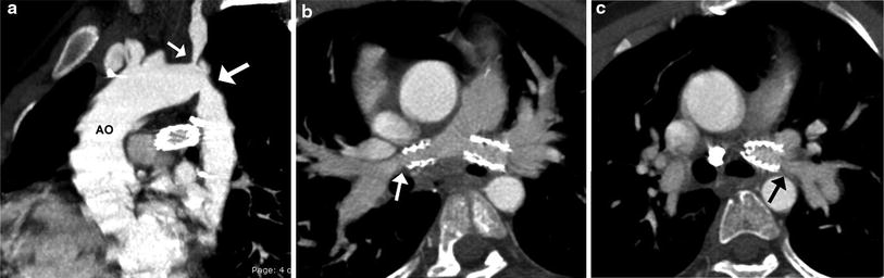
Fig. 3
TOF and coarctation status post repair. Sagittal oblique MIP image (a) shows recurrent stenosis at the aortic isthmus (large arrow) and proximal left subclavian artery (small arrow) following an end-to-end anastomosis for coarctation repair. Oblique axial MIP images show patent bilateral proximal branch PA stents with narrowing of the RPA (arrow in b) and LPA (arrow in c) distal to the stents
4 Clinical Applications
4.1 Pulmonary Vasculature
4.1.1 Pulmonary Arteries
In patients with TOF with pulmonary atresia, precise preoperative delineation of the presence, size and confluency of the pulmonary arteries, and major aortopulmonary collateral arteries (MAPCAs) is necessary for surgical planning. This diagnostic task can be readily accomplished with cardiac MDCT (Goo et al. 2005a; Greil et al. 2006) (Fig. 4). As a result, the procedure time of catheter angiography and possibility of overlooked MAPCAs can be substantially reduced. Nonetheless, conventional catheter angiography is necessary for identifying communications between pulmonary arterial feeders. Abnormalities of the branch pulmonary arteries that are well depicted on MDCT include an abnormal origin or course such as in truncus arteriosus or pulmonary artery sling (Fig. 5). The branch pulmonary arteries can be atretic, stenotic, or hypoplastic related to decreased blood flow during growth (Fig. 6), extrinsic compression, or as a result of a surgically altered course or anastomosis such as a palliative shunt between the systemic and pulmonary artery circulation (Fig. 7).
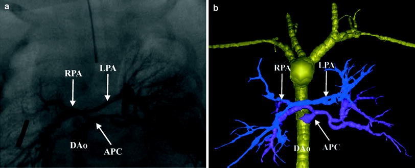
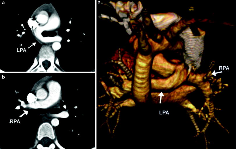
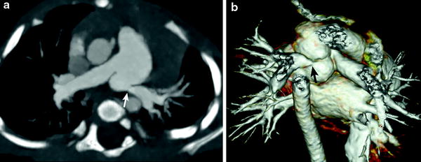
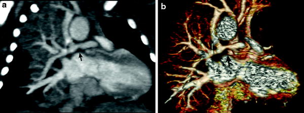
Fig. 4
Tetralogy with pulmonary atresia and MAPCAs. Segmented 3D surface model from MDCT angiography demonstrates a collateral (APC) from the descending aorta (Dao) to the left and right lung connecting to the hypoplastic left (LPA) and right (RPA) pulmonary arteries (a). Corresponding X-ray angiogram (b) (Greil et al. 2006, used with permission)
Fig. 5
Pulmonary artery sling. Axial MDCT images demonstrate the LPA (a) arising from the RPA (b) and passing posterior to the carina. A 3D volume rendered posterior image (c)
Fig. 6
Branch pulmonary artery stenosis. Axial oblique MIP image (a) and volume rendered image (b) demonstrate a juxta-ductal stenosis (arrow) and kinking of the LPA
Fig. 7
Functional single ventricle status post right modified BT shunt. Coronal oblique MIP image (a) and volume-rendered image (b) show a stenosis of the RPA (arrow) proximal to the shunt
4.1.2 Pulmonary Embolism
Pulmonary embolism (PE) is an uncommonly diagnosed condition in children. The clinical presentation is often subtle because symptoms are nonspecific and can be masked by the underlying clinical condition. Delays in diagnosis are frequent because definite signs of associated pulmonary or cardiac dysfunction appear to be less common in children than in adults. Specific risk factors for PE in the pediatric patient include associated deep venous thrombosis, indwelling central venous catheters, cardiac surgery, thrombotic disorders, vascular malformations, and malignancy and multiple factors are often present in the same patient (Babyn et al. 2005). PE may complicate CHD particularly after surgical treatments, such as cavopulmonary connections (Fig. 8). Diagnostic strategies for detection and treatment of PE in children are mostly extrapolated from evidence that has been compiled in the adult literature.

Fig. 8
Coronal reformatted (a) and axial (b) images of a Fontan patient demonstrate extensive thrombus (arrows) extending from the Fontan pathway into the main and segmental branches of the LPA
CT has become the first choice of imaging modalities for detection of PE in symptomatic patients. MDCT has led to improved visualization of peripheral pulmonary arteries for detection of small emboli (Lee et al. 2011), and conventional pulmonary angiography is now rarely performed. Once regarded as the best first noninvasive study for the diagnostic work-up of PE, nuclear medicine perfusion scintigraphy is also now infrequently requested because as many as 73 % of studies are interpreted as indeterminate (PIOPED 1990) and have poor interobserver correlation (Blachere et al. 2000), and there is limited ability to make alternative diagnoses. Despite excellent diagnostic accuracy of MDCT in detecting PE, thromboembolic risk factors should be used as a first-line triage tool to guide more appropriate use of CT pulmonary angiography in children, with associated reductions in radiation exposure and costs (Lee et al. 2012).
MDCT angiography findings of acute pulmonary embolism include intraluminal filling defects in the main and branch pulmonary arteries that can partially or completely fill the lumen (Fig. 9). When the embolus completely fills the lumen of a branch pulmonary artery, the artery can enlarge relative to similar-sized arteries in the hilum. Lung parenchymal findings with PE include peripheral wedge-shaped opacities, hyperlucency, and mosaic perfusion. Findings of acute right ventricular failure, such as right ventricular enlargement and septal flattening, may be present in severe cases.
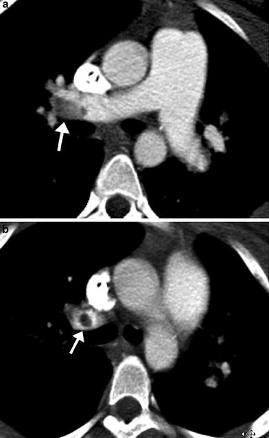
Fig. 9
Acute pulmonary embolism. Axial images from an MDCT angiogram in a pediatric patient with respiratory distress demonstrate a well-defined filling defect in the distal RPA (arrow in a) extending into the upper lobe pulmonary artery (arrow in b)
A classic finding of chronic PE is an intraluminal filling defect that makes an obtuse angle with the vessel wall and creates an appearance of asymmetric wall thickening (Fig. 10). Contrast-enhanced peripheral arteries can have irregular wall thickening related to recanalization and the residual thrombus may be calcified. Enlarged bronchiolar and systemic collateral arteries can also be seen in association with chronic PE.
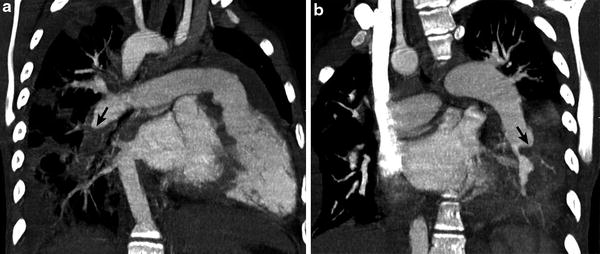
Fig. 10
Repaired tetralogy of Fallot status post pulmonary valve replacement with recurrent bacterial endocarditis. Oblique coronal CT images (a, b) demonstrate hypodense clot (arrow) making obtuse angle with the vessel wall in the descending branch of the RPA consistent with chronic pulmonary embolism
Recently, dual-energy CT scanning enables us to evaluate PE and lung perfusion defects at the same time (Fig. 11). In addition to the accurate diagnosis of PE, pulmonary blood volume assessment using dual-energy CT can predict right heart strain and clinical outcome (Bauer et al. 2011). This emerging CT imaging technique for evaluating PE may also be useful in pediatric patients (Goo 2010b; Zhang et al. 2012).
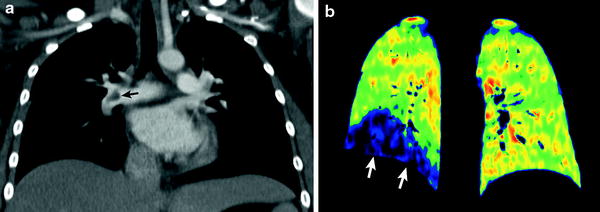
Fig. 11
Dual-energy lung perfusion CT in a child with leukemia and pulmonary embolism. Coronal weighted-average CT image (a) shows an acute embolus (arrow in a) in the RPA. Coronal iodine map (b) reveals a well-circumscribed perfusion defect (arrows in b) in the right lower lung
4.1.3 Pulmonary Veins
MDCT angiography is quite useful and accurate in evaluating anomalous pulmonary venous connections when echocardiography is limited in fully identifying types and obstructions of these total or partial anomalous pulmonary venous connections (Kim et al. 2000). When associated with CHD, pulmonary vein stenosis (PVS) is most often extrinsic due to compression by other vascular structures, or associated with the site of a prior surgical anastomosis (Fig. 12). PVS can rarely be intrinsic and rapidly progressive and refractory to all forms of treatments (Latson and Prieto 2007; Devaney et al. 2006). Progressive PVS can occur in children with or without CHD and MDCT can assess PVS noninvasively and accurately (Ou et al. 2009).
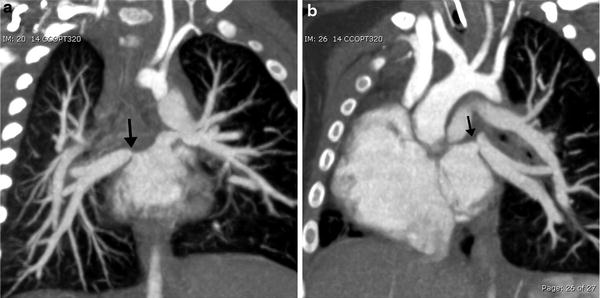
Fig. 12
Total anomalous pulmonary venous return status post repair with pulmonary venous stenosis. Coronal oblique MIP images demonstrate focal stenosis (arrows) of the right (a) and left (b) pulmonary veins. (Courtesy of Sjirk Westra)
Congenital pulmonary venolobar syndrome or scimitar syndrome is a heterogeneous group of congenital anomalies of the thorax that may occur singly or in combination. The main components of the congenital pulmonary venolobar syndrome are hypogenetic lung (lobar agenesis, aplasia, or hypoplasia), partial anomalous pulmonary venous return, absence of a pulmonary artery, pulmonary sequestration, systemic arterialization of the lung, absence of the inferior vena cava (IVC), and accessory diaphragm (Konen et al. 2003). Horseshoe lung may be rarely associated with this syndrome (Goo et al. 2002). MDCT provides a complete evaluation of all pulmonary and systemic vascular, tracheobronchial and pulmonary parenchymal anomalies, necessary in patients under consideration for surgical repair (Fig. 13).
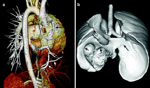
Fig. 13
Scimitar syndrome. Volume-rendered CT image (a) shows partial anomalous pulmonary venous return of the right upper pulmonary vein to the right atrium (long arrow in a). Systemic collateral arteries supplying the right lower lung (short arrows in a) is also depicted. Shaded surface display CT image (b) reveals right lung hypoplasia, horseshoe lung (long arrow in b), and right diaphragmatic hernia (short arrows in b)
4.2 Aorta
4.2.1 Coarctation of the Aorta
Coarctation of the aorta is a congenital obstructive aortic arch anomaly presenting with arch hypoplasia and focal narrowing of the aortic isthmus at the junction of the ductus arteriosus and the aorta. MDCT can demonstrate anatomic features of the anomaly and collateral arteries, if present (Fig. 14), that are helpful for optimal surgical planning. It should be noted that the anomaly is a dynamic process showing progressive obstruction in young infants when the patent ductus arteriosus (PDA) is present. Following surgical repair of coarctation, MDCT can be used to detect residual stenosis, recoarctation, or aneurysm formation at the repair site. In order to avoid radiation exposure in children, MRI may be favored for long-term follow-up after surgical repair. MDCT is the imaging method of choice for evaluating associated airway abnormalities and in-stent stenosis after stent placement. In addition, MDCT is also useful for assessing early post-procedural complications, such as pseudoaneurysm formation and dissection (Fig. 15).
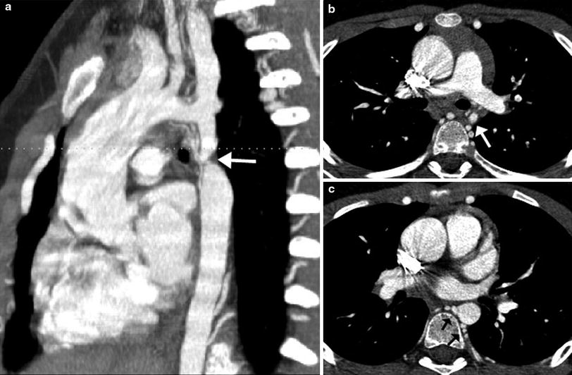
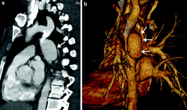
Fig. 14
Coarctation with transverse arch hypoplasia. Sagittal oblique MIP image (a) demonstrates a severe discrete narrowing (arrow) of the aortic isthmus. Axial reformatted images show the markedly small caliber of the isthmus (arrow in b) and numerous dilated intercostal collaterals joining to the proximal descending aorta (arrows in c) (Courtesy of Shi-Joon Yoo)
Fig. 15
Dissection and pseudoaneurysm of the thoracic aorta following balloon dilatation and stenting of coarctation. Oblique sagittal MIP (a) and volume rendered (b) images demonstrate a stent at the aortic isthmus with a dissection and large pseudoaneurysm (arrow) protruding from the aorta. The patient required an additional covered stent to be placed which closed the entrance of the pseudoaneurysm into the thoracic aorta. The pseudoaneurysm was shown to be thrombosed on subsequent imaging
4.2.2 Interrupted Aortic Arch
Interrupted aortic arch (IAA) is a rare aortic anomaly defined as a complete luminal and anatomic discontinuity of the aortic arch. The anomaly is classified as three types depending on the site of interruption, i.e., distal to the subclavian artery in type A, between the second carotid and ipsilateral subclavian arteries in type B, and between two carotid arteries in type C. Type B is most common in the Western population (Fig. 16), while type A is most common in the Asian population (Lee et al. 2006). Each type may be further divided into three subtypes depending on the origin of the subclavian artery, i.e., normal in subtype 1, aberrant in subtype 2, and isolated in subtype 3. In addition to the anatomic types of IAA, cardiac CT may be used to evaluate the distance between the proximal and distal segments of IAA, the sizes of a PDA, the aorta and the thymus, the presence of subaortic stenosis, and other cardiac defects (Yang et al. 2008). In IAA, a right aortic arch is almost always associated with DiGeorge syndrome and/or chromosome 22q11 deletion (McElhinney et al. 1999b). As in coarctation of the aorta, IAA may be associated with the bicuspid aortic valve and other components of Shone complex including supravalvular mitral membrane, parachute mitral valve, and subaortic stenosis.
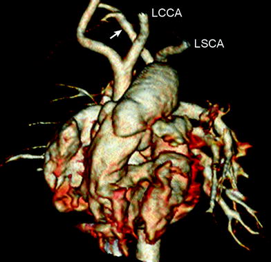
Fig. 16
Interrupted aortic arch type B2. Volume-rendered CT image shows interruption of aortic arch between the left common carotid artery (LCCA) and the left subclavian artery (LSCA). Aberrant right subclavian artery (arrow) is noted
4.2.3 Valvular and Supravalvular Aortic Stenosis
Valvular aortic stenosis occurs in approximately 3–6 % of patients with CHD and is often associated with a congenital bicuspid aortic valve. Although the effective valve area can be reduced at birth, the stenosis of a bicuspid valve is progressive and clinical symptoms do not usually develop until young adulthood. MDCT is seldom used for evaluating valvular aortic stenosis because anatomic details of the aortic valve in children are not well-seen on CT and high radiation dose is necessary for the complete assessment of the aortic valve. The surgical approach to aortic valve replacement for severe congenital aortic stenosis in young patients is difficult because placement of a mechanical valve is not a good option because of the risk of long-term anticoagulation. Other options include placement of homograft or xenograft valves. In the Ross procedure, the stenotic aortic valve is replaced with the patient’s pulmonary valve, and a right ventricle to pulmonary artery conduit is placed.
Supravalvular aortic stenosis (SVAS) may be non-syndromic or associated with Williams syndrome. ECG-synchronized cardiac CT can show not only SVAS, but also the bicuspid aortic valve, dilated coronary arteries, coronary ostial stenosis, and left ventricular hypertrophy (Liu et al. 2007). SVAS may be focal (the “hourglass” appearance) (Fig. 17) or diffuse (10–30 % of cases), starting at the sino-tubular junction. Aortoplasty is indicated in symptomatic patients or in those with a transaortic valve gradient greater than or equal to 50 mmHg (Scott et al. 2009).
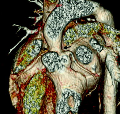
Fig. 17
Supravalvular aortic stenosis in Williams syndrome. Volume-rendered CT image shows a focal stenosis at the sinotubular junction (arrows). In addition, there is no evidence of coronary ostial stenosis
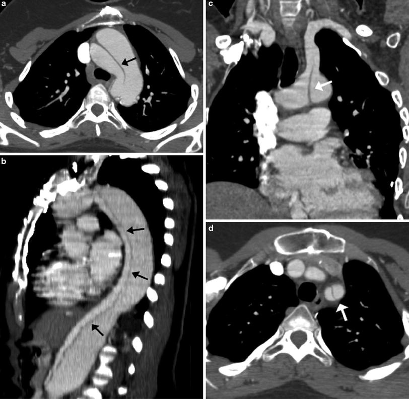
4.2.4 Connective Tissue Disorders
Marfan syndrome and type IV Ehlers-Danlos syndrome are connective tissue disorders that can have cardiovascular manifestations. Both are associated with cystic medial necrosis of the aortic wall, which adversely affects the ability of the aortic wall to withstand systemic pressures, leading to dilatation. The characteristic findings of the aorta include dilatation of the aortic root and proximal ascending aorta and effacement of the sino-tubular junction. The dilatation of the aortic root results in suboptimal coaptation of the aortic valve cusps, which can lead to aortic regurgitation that can further weaken the aortic wall as more throughput volume is needed to maintain cardiac output. Both echocardiography and MRI can be used for serial follow-up of ascending aorta size and aortic regurgitation in patients with Marfan syndrome. CT may be used in some patients with severe chest wall deformity limiting echocardiographic evaluation or who cannot tolerate lengthy MRI evaluation (Ha et al. 2007). In general, when the maximum diameter of the ascending aorta is 1.5 times that of the descending thoracic aorta at the level of the diaphragm, an aneurysm is considered to be present. In addition to the maximal diameter of the aortic root, its growth rate should be considered in determining the optimal timing for surgical replacement of the aortic root and/or ascending aorta. Serious complications of Marfan’s or type IV Ehlers-Danlos syndrome include dissection and rupture of the ascending aorta (Fig. 18). Although transesophageal echocardiography (TEE) or MRI could be performed urgently if dissection is suspected, MDCT angiography with multiplanar reconstruction is a highly sensitive and specific technique for the detection and characterization of the extent and orientation of the intimal flap, delineation of the true and false lumens, presence of intramural hematoma, and involvement of the major aortic branches and coronary arteries (McMahon and Squirrell 2010).