Fig. 10.1
Anatomy of the carpal tunnel: the proximal level of the carpal tunnel, delineated by the pisiform and the scaphoid carpal bones. The transverse carpal ligament forms the carpal tunnel roof. The median nerve and flexor tendons (surrounded by their tendon sheaths) pass through the tunnel, with the median nerve lying palmar and radial TLC Transverse carpal ligament
The principle contents of the CT include: (1) the median nerve, typically accompanied by the highly variable arteria mediana and (2) nine extrinsic flexor tendons (four tendons of flexor digitorum superficialis and four tendons of flexor digitorum profundus in common flexor sheath as well as one tendon and sheath of flexor pollicis longus). The muscles of the nine extrinsic flexor tendons which traverse the CT originate from the medial epicondyle of the humerus and the anterior aspect of the radius, ulna, and interosseous membrane. The musculotendinous junctions are found proximal to the proximal edge of the CT. In the tunnel flexor digitorum superficialis, tendons of middle and ring finger are superficial than that of index and little fingers, whereas the median nerve lies most superficially, just beneath the flexor retinaculum passing between the tendons of flexor digitorum superficialis ulnarly and flexor carpi radialis radially, dorsal or dorso-radial to the palmaris longus tendon. The tendons are surrounded by mesodermal tissue, which provides vincular blood supply to the tendons as well as extratendinous lubrication and nutrition. The mesodermal tissue is composed of a continuous layer of mesoderm, forming invaginated loops around the individual tendons. The source of the blood supply to the tendinous vincula is the anterior interosseous artery [5]. Just above this layer of mesodermal tissue is the fibrous layer of the anterior wrist joint capsule which is continuous with the periosteum of the carpal bones and the transverse carpal ligament.
Recently, lumbrical muscle incursion into the CT has also been implicated as a possible cause for CTS. Besides the margins and the anterior surface, the origin of the lumbricals also extends on the posterior surface of flexor digitorum profundus tendons. In a study carried out by Joshi et al. [6], they found that the proximal attachment of the second lumbrical was extending into the CT compared to the rest of the lumbrical muscles whereas in some cases the first lumbrical was found in continuation with the fleshy fibers of flexor digitorum profundus. Siegel et al. [7] have described the origin of lumbricals being significantly proximal in patients with CTS, whereas, Cobb et al. [8] have described that lumbrical muscle incursion into the CT during finger flexion is a normal occurrence. The incursion of the lubmrical muscles into the CT varies according to the hand position. All the lumbricals extend proximally into the CT when passive finger flexion was performed whereas they extend only up to the intermediate/distal parts of the CT in extended position of fingers. Siegel et al. [7] have stated that in those performing repetitive hand motions, lumbricals had significantly larger and proximal origins in the CT which can be a contributory factor in the causation of CTS. Cobb et al. [9] described “first test” to ascertain the CTS due to lumbricals muscle incursion in the CT. According to this test, if a person is asked to keep the hand in a sustained fist position for 45 s it would result in numbness in the area of distribution of median nerve.
Median Nerve
The median nerve is composed of branches from the C5 through T1 spinal cord nerve roots. It enters the anterior compartment of the forearm via the cubital fossa. It travels between the flexor digitorum superficialis and profundus muscle bellies, often within the deep epimysium of the flexor digitorum superficialis. Further distal in the forearm, the median nerve becomes more superficial, passing between the tendons of flexor digitorum superficialis ulnarly and flexor carpi radialis radially, dorsal or dorsoradial to the palmaris longus tendon. The palmar cutaneous branch of the median nerve arises proximal (approximately 5 cm proximal to the wrist crease) to, and does not pass through, the CT; thus, sensation in the central palm remains unaffected in CTS patients. It parallels the median nerve for 1.6–2.5 cm and then courses separately under the antebrachial fascia between the tendons of palmaris longus and flexor carpi radialis [10]. After exiting the CT, the median nerve divides into six terminal branches. The recurrent motor branch supplies innervation to the thenar muscles (flexor pollicis brevis, abductor pollicis brevis, and opponens pollicis, in addition to the first and second lumbrical muscles); three proper digital nerves, including the radial and ulnar proper digital nerves to the thumb and the radial proper digital nerve to the index finger; as well as two common digital nerves emerge from the median nerve. The point of departure of the recurrent motor branch from the median nerve may vary in its relation with the distal edge of the transverse carpal ligament. Frequently (46 %), the recurrent motor branch passes in a retrograde fashion into the thenar musculature, whereas in 31 %, the recurrent motor branch diverges from the median nerve deep to the transverse carpal ligament, within the confines of the CT, and passes around the distal edge of the transverse carpal ligament to enter the thenar musculature. Less frequently (23 %), the recurrent motor branch diverges from the median nerve within the limits of the CT and appears to perforate the ligament in its course to the thenar musculatures [11]. The fascicles ultimately destined for the recurrent motor branch have been found in 60 % of dissections to arise from the extreme radial aspect of the median nerve, in 22 % from the central–anterior aspect, and in the remaining 18 % between the extreme radial-anterior and the central aspect of the median nerve. The variation in the location of the motor branch of the median nerve with respect to the other fascicles may predispose to thenar muscle wasting in CTSs with unequal distribution of demyelination and degeneration between fascicles.
Vascular Anatomy
The vascular anatomy of the median nerve shows that the median artery of the forearm is an accessory artery arising from the ulnar artery at the proximal forearm, which courses alongside the median nerve to the CT. Along with the interosseous artery, the median artery is the main route of blood supply to the hand in embryos. After the eighth week of gestation, it regresses and is replaced by the ulnar and the radial arteries. Pecket et al. [12] described three different variations of median nerve vascularization. The first one (70 %) entails radial and ulnar arteries converging into the superficial and deep palmar arches, with the median nerve supplied by the superficial palmar arch and an anastomosis between the two arteries as well as by the forearm muscular branches. The second type (10 %) originates from the radial and ulnar arteries and a median artery that branches out directly from the brachial artery or from the bifurcation of the latter into radial and ulnar arteries. The median artery runs superficial to the median nerve, and at the palm it separates into the finger branches which supply the second, third, and fourth fingers; with no evidence of either the superficial or deep palmar arches. The third type (20 %) shows the median artery associated with the superficial palmar arch. In case the median artery persisted into adult life, it runs on its ulnar side in normal median nerve, whereas, when associated with a bifid median nerve, the artery courses between the two nerve trunks.
Studying the intrinsic vascular anatomical pattern of the median nerve [13] revealed that the rich surface epineurial capillary plexus is distinct from the peri-fascicular capillary plexus, and is fed and drained, both by the arteries and veins of the surface epineurium and by the underlying interfascicular vessels. This arrangement is not peculiar to the median nerve, for it has been demonstrated also in the antebrachial ulnar nerve. The deep venous drainage of the surface “epineurium” may serve to prevent the venous engorgement resulting from a relatively minor degree of external compression of a segment of the nerve trunk. The characteristic finding of relatively large arteries in the interfascicular connective tissue at the distal end of the median nerve appears of interest since Denny-Brown and Brenner [14] have shown that the “compartmented structure” of a peripheral nerve trunk may serve to protect intraneural vessels from the effects of external compression. The architecture of the median nerve in approximately its distal 3 in. is extremely fascicular, and expectedly these large interfascicular vessels would be highly resistant to the effects of external compression. This would explain the US power Doppler (PD) findings which are discussed later in this chapter.
High division of the median nerve proximal to the CT (known as a bifid median nerve) is a median nerve anomaly with an incidence rate of 2.8 % [15]. This rare anomaly is often associated with various clinically relevant abnormalities, such as vascular malformations (persistent median artery), [16] aberrant muscles [17], and CTS. The two parts of the nerve may be equal in size [18], or predominance may exist of either the radial or ulnar part [19]. Larger radial trunks approximately equal in size to a normal median nerve [16], however, and larger ulnar trunks were also reported [19]. When pathology of the median vessels exists, the bifidity may be missed if the small ulnar trunk is surrounded by the abnormal median vessels. Accessory lumbrical muscles passing through the bifid nerve, and bifid median nerves in which the radial part passes through a separate compartment of the CT [20, 21] were also reported.
Pathophysiology
In many cases, the onset of CTS is insidious and progressive . In these instances, the etiology is usually illusive and consequently labeled as “idiopathic.” A growing body of evidence indicates that the common pathway for the CTS development is increased pressure within the carpal canal. Experimental studies suggested that the changes in the CTS are linked to the amount and duration of the interstitial fluid pressure and may be reversible up to a point with management [22]. Therefore, understanding the pathophysiological changes in the CT and median nerve would have a positive impact not only on the diagnosis but also on the management of the condition (Fig. 10.2). Earlier reports revealed that CTS pathophysiology is multifactorial including anatomic, physiologic, biochemical, mechanical, histologic as well as pathological components which integrate to explain and characterize this syndrome .
Fig. 10.2
Pathophysiologic changes in carpal tunnel syndrome and their impact on the median nerve sonography
Anatomic (Mechanical Pressure)
While the CT cross-sectional area (CSA) diminishes with progressive wrist flexion or extension, its interstitial pressure increases. Normal pressure in the tunnel has been recorded in the range of 2–10 mm Hg [23]. Extension increases the pressure tenfold whereas wrist flexion increases it eightfold [24]. Therefore, repetitive hand movements have been implicated as one of the many risk factors for CTS. Experimental studies have suggested a dose-response curve—the greater the duration and amount of pressure, the more significant is the neural dysfunction [22].
Physiologic (Stasis-Ischemic Injury)
Earlier reports revealed that exposure of the nerve to repetitive mechanical forces leads to a consequent demyelination [25]. Nerve demyelination starts at the compression site, and can then spread to the entire internodal segment, leaving the axons intact. This leads to a block of the nervous transmission (neuroapraxia). Persistence of the nerve compression leads to interruption of the blood flow to the endoneural capillary system which in turn would lead to venous stasis followed by ischemia at the capillary level. This in turn leads to alterations in the blood–nerve barrier and development of endoneural edema. This starts a vicious cycle consisting of venous congestion, ischemia, and local metabolic alterations [25, 26], resulting in axonal degeneration, macrophage attraction and activation, release of inflammatory cytokines, nitric oxide, and development of “chemical neuritis” if it continues for a substantial amount of time. This ends in further decrease in the intraneural blood flow followed by fibroblastic activity and scar formation, resulting in destruction and replacement of the normal epineurium with scar tissue and later intraneural damage [26]. Morphological changes in the form of nerve deformity (flattening and hourglass deformity) may also occur at this stage.
Biochemical
Intermittent local ischemia and reperfusion during periods of recovery lead to local biochemical changes in the loose connective tissue in the CT. Under normal conditions, the tendency of loose connective tissue to expand is usually countered by collagen and microfibrillar networks. During periods of ischemia and reperfusion, there is a negative interstitial fluid pressure, suggesting that the tensile forces exerted on the tenosynovium are reduced due to altered gylocosamine and hyaluronan content, augmenting the diffusion of fluid into the tenosynovium. In a study carried out by Sud et al. [27], the authors reported that fluid diffusion occurs at a faster rate and in higher volume in tenosynovium harvested from CTS patients than those from normal tenosynovium. Progressive tenosynovial edema tends to compress the structures in the CT. Furthermore, the altered proteoglycan ratios may reduce the ability of the synovium to bear the compression forces, thus increasing the force incident on the median nerve inside the carpal canal [28]. In contrast with the tendons which are firm and resistant to ischemia, the median nerve is pliable and vulnerable to pressure.
Biomechanical
Nerve fibers have layers of connective tissue: the mesoneurium, epineurium, perineurium, and endoneurium; which is the most intimate layer. The extensibility of these layers is critical to nerve gliding, which is necessary to accommodate joint motion; otherwise nerves are stretched and become injured [29]. The median nerve is expected to move up to 9.6 mm with wrist flexion and slightly less with extension [30]. Chronic compression resulting in fibrosis would inhibit nerve gliding, leading to injury and therefore scarring of the epineurium as well as mesoneurium. This causes the nerve to adhere to the surrounding tissue, or at least cause variable degrees of excursion between the flexor tendons and the median nerve, resulting in traction of the nerve during movement as the nerve attempts to glide from this fixed position [31]. Consequently, this would cause strain and microdamage to the median nerve.
Histological
The inner cells of the perineurium and the endothelial cells of endoneurial capillaries form the blood–nerve barrier which accompanies the median nerve through the CT. These microvessels are formed from nutrient branches that arise from the radial and ulnar arteries, proximal to the flexor retinaculum. An increase in pressure within the tunnel can cause a breakdown of vasculature within this barrier, leading to accumulation of proteins and inflammatory cells [31]. This may induce a miniature closed compartment syndrome by increasing the permeability, contributing to increased endoneurial fluid pressure and development of an intrafascicular edema [32], hence the nerve appears swollen. Similarly, repetitive exposure of the tendons to compression or tensile strength can lead to micro-damage of the synovial tissue lining the tendons within the CT. This leads to thickening of the synovial tissue, and hypertrophy of the tendon, increasing its CSA which in turn increases the pressure within the CT [33].
Pathological
Tenosynovitis, inflammation of the synovial tissue of the flexor tendons, is one of the most common pathological predisposing factors to CTS [34]. This was supported by the presence of increased levels of prostaglandin E2 and vascular endothelial growth factor in synovial biopsy tissue from patients with symptomatic CTS [35]. This leads to an increase in fibroblast density, collagen fiber size, vascular proliferation, and type III collagen in the synovial connective tissue [36]. The outcome is constrictive scar tissue formation around the median nerve [37], which in turn can result in the nerve tethering.
Causes of Carpal Tunnel Syndrome
Though median nerve entrapment symptoms are the primary manifestation of CTS, the encroachment on the median nerve is usually secondary to another focal pathology . This can be either a decrease in the tunnel size (mainly osseous causes) or increase in the volume within the tunnel-confined space. Table 10.1 shows the most common causes in each category. However, the most recently found common cause of CTS is repetitive stress injury, such as in computer keyboard operators, tablets, or mobile phones .
Table 10.1
Causes of carpal tunnel syndrome
Osseous causes of tunnel narrowing | Increased volume causes of tunnel narrowing |
|---|---|
Malalignment of carpal bones | Tendon sheath enlargement (tenosynovitis) (Fig. 10.3) |
Displaced fractures | Synovial proliferation (rheumatoid arthritis) |
Callus formation | Hypertrophied muscles (occupational) |
Hypertrophic bone changes | Increased fat (obesity) |
Focal swelling, e.g., ganglion (Fig. 10.4) |
Fig. 10.3
a A diagram showing the compression of the median nerve by inflamed tendons’ sheath. b Gray scale US using Esaote Mylab 25 system: transverse. c longitudinal view showing tenosynovitis flexors of the hand. TLC transverse carpal ligament. Flex. Dig. Sup. flexor digitorum superficialis, Flex. Dig. Prof. flexor digitorum profundus
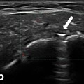
Fig. 10.4
Gray scale US using Esaote Mylab 25 system: palmar longitudinal view showing a space occupying lesion (ganglion) compressing the median nerve at the carpal tunnel proximal entrance
US Scanning of the Carpal Tunnel
Anatomic Landmarks and Imaging Technique
One of the most important factors which are essential for the routine median nerve US is patient positioning and identifying landmarks with high diagnostic accuracy and reliability for median nerve assessment . It is advisable that the patient sits with the forearm resting comfortably on a flat surface, with the elbow in mid-flexion and the wrist in supination while the fingers are semi-extended. In most studies, US assessment of median nerve was performed at the proximal CT (at the level of the pisiform bone or distal forearm crease) [38–40]. Furthermore, the US outcome measures recorded at this level demonstrated the highest sensitivity and specificity [41, 42]. In addition, the measurement at this level was found easier to perform and achieved high reproducibility factors.
Imaging should be carried out with the transducer in a plane perpendicular to the tendon surface to eliminate the anisotropic effect. The weight of the probe should be applied without additional pressure. The tunnel contains the flexor digitorum tendons which are hyperechoic as well as the median nerve (anterior to the tendons). The nerve appears as hypoechoic with multiple bright reflectors and a hyperechoic border (Fig. 10.5). At the proximal wrist, the normal median nerve appears elliptical (Fig. 10.6) and flattens progressively as it courses distally. However, while its shape may get quite variable, its size remains constant and within the tunnel, the nerve remains in intimate contact with the flexor retinaculum. In the longitudinal imaging plane, the nerve enters the tunnel parallel and superficial to the flexor digitorum tendons. Similar to the transverse view, the nerve in this plane demonstrates hyperechoic continuous anterior and posterior borders (the nerve sheath) and is easily distinguished from the distinctive fibrillar tendons sonographic pattern which lies posteriorly. To minimize errors due to differential loads, a gel pad (Sonar Aid) of thickness about 3 mm can be used. Images can be magnified also in order to reduce measurement error .
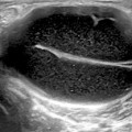
Fig. 10.5
Gray scale US using Esaote Mylab 25 system: Palmar longitudinal view at the proximal carpal tunnel inlet showing the normal sonographic median nerve fascicular pattern which appears as multiple bright reflectors with a hyperechoic border
Fig. 10.6
Gray scale US using Esaote Mylab 25 system: Palmar transverse view at the proximal inlet of the carpal tunnel showing normal elliptical median nerve
Scanning Tips
As the median nerve changes in both shape and size as the probe is moved along the nerve from the forearm to the hand, the nerve can be assessed at different levels. To ensure the reliability of the scanning, most studies have chosen to standardize their “level” by reference to anatomical landmarks such as the pisiform bone or the hook of the hamate bone, or the distal wrist crease (which closely approximates to the pisiform bone). This is important not only to a new ultrasonographer but is also confounded by the fact that the median nerve is not actually longitudinally fixed in place. With the movement of the wrist and fingers, the normal median nerve slides up and down through the CT and also across the tunnel. On transverse scanning of the median nerve, at the wrist crease, the nerve may change in appearance as the wrist and fingers move or the tendons may push the nerve around and deform its outline. Therefore, standardizing the hand and finger position is essential for accurate reproducible measures.
Another challenge that the sonographer may face appears when the median nerve starts to divide early. While in most subjects the median nerve at the CT appears as a single structure, in some patients, it starts to divide into branches above the CT and a transverse image may show two or even three nerves, providing yet a challenge regarding how to measure them. Options include: either to measure them all individually and add them together, draw a boundary which goes round them all (which may be what the nerve sheath does in some cases), or just conclude that these cannot be measured and compared with subjects who only have a single nerve trunk at the CT.
US Findings in Carpal Tunnel Syndrome
An early diagnosis based on clinical and electrodiagnostic findings has been the standard for assessment of CTS patients aiming at preventing permanent nerve damage and functional sequelae [43] . The development of high-resolution US transducers (7–15 MHz) has allowed noninvasive evaluation of normal and abnormal appearances of the median nerve as well as the other contents of the CT. Over the past years, several studies [44–48] were published showing the value of US as a tool for the diagnosis of the condition. US enables the treating physician to detect changes in nerve shape and exclude anatomic variants and space-occupying alterations such as ganglion cysts and tenosynovitis [49, 50]. It has several advantages over magnetic resonance imaging (MRI), including being relatively fast and inexpensive and allowing additional dynamic as well as blood flow imaging with relatively little additional time. Table 10.2 depicts US findings seen on assessment of the CT which can be stratified into subjective and objective outcomes. The next section focuses on the objective US outcomes and methods of their assessment/measurement .
Table 10.2
Sonographic carpal tunnel changes stratified into subjective and objective outcomes
Subjective criteria | Objective criteria |
|---|---|
Flattening of the nerve, especially at the level of the hamate bone | The mean cross-sectional area of the median nerve is greater than 10 mm2 at the pisiform bone level |
Volar bulging of the flexor retinaculum | The flattening ratio of the nerve (transverse diameter divided by Antero-posterior (AP) diameter) is greater than 4:1 at the level of the hamate bone |
Enlargement of the median nerve as it enters the carpal tunnel | Volar bulging of the flexor retinaculum is greater than 3.1 mm |
Large fluid or fat layer surrounding the tendons | Power doppler assessment of the median nerve vasculature |
Decreased mobility of the median nerve on flexion and extension of the fingers, hand, or wrist |
US Measures of the Median Nerve
Median nerve compression is revealed on US by the classic triad of nerve swelling, nerve flattening, and palmar bowing of the flexor retinaculum .
Cross-Sectional Area
Considering the underlying pathophysiological changes, compression of median nerve leads to congestion of epineural and endoneural veins, subsequently causing nerve edema which manifests as increase in the median nerve CSA (Fig. 10.7). Usually, the CSA of the median nerve (recorded in mm2) is measured at the proximal CT (at the level of the pisiform bone). Duncan et al. [46] endorsed a direct method for measurement, which is calculated automatically by tracing the inner margin of the median nerve epineurium.
Fig. 10.7
Gray scale US using Esaote Mylab 25 system: Palmar view at the proximal inlet of the carpal tunnel showing: a Transverse view of the median nerve swelling manifested by increased median nerve cross-section area in a subject with carpal tunnel syndrome. b Longitudinal view showing compression of the median nerve at the proximal inlet of the carpal tunnel whereas there is increased nerve width at both tunnel inlet and outlet. MN median nerve, Fl. Tendons flexor tendons, CT Carpal Tunnel
The diagnostic accuracy of this method has been reported high [51–57] although the concluded cutoff values vary because of differences in the gold standards or devices used for diagnosis, as well as the severity of the disease or other factors. The diagnostic sensitivity and specificity of this approach (CSA measurement at the tunnel inlet/the distal wrist crease) was found to be 67 and 97 %, respectively [56]. When this criterion was combined with the results of nerve conduction studies (NCSs), the sensitivity and specificity were 84 and 94 %, respectively [57]. CSAs larger than 9 mm2 [58, 59] and 10 mm2 [60, 61] recorded at the tunnel inlet in patients with CTS were reported the most appropriate median nerve cutoff values to identify abnormal median nerve CSA in comparison to control patients.
Median Nerve Flattening
Flattening of the median nerve (Fig. 10.8) reflects the morpho-pathologic changes in response to persistent pressure on the nerve. To calibrate the degree of flattening, flattening ratio (FR) was suggested to quantify the change of the median nerve shape by measuring the ratio of the major axis to the minor axis at the tunnel proximal inlet (at the level of pisiform bone) [62–64]. This is the ratio of the mediolateral diameter to the anteroposterior diameter on cross sections. A ratio of one would indicate a round structure. Earlier studies [36, 56–61] showed a trend of increase in the FR measure with increase in the severity of CTS (as evident from other US measures and electromyography findings). A recent study [65] discussed the value of median nerve flattening for the prediction of management outcome, which is discussed later in this chapter.
Fig. 10.8
Gray scale US using Esaote Mylab 25 system: Palmar transverse view at the proximal inlet of the carpal tunnel showing flattening of the median nerve (The flattening ratio (FR) is defined as the ratio of the nerve’s transverse axis to the anteroposterior axis)
Bowing of the Transverse Carpal Ligament
The palmar bowing of the flexor retinaculum is a measure used to quantify the internal pressure exerted on the retinaculum from the contents within the CT. Exaggerated palmar bowing of the flexor retinaculum has been reported to predict the CTS diagnosis [66]. The palmar bowing of the flexor retinaculum is displacement (measured in mm) of the retinaculum of a line connecting the pisiform bone with the scaphoid bone (Fig. 10.9). Earlier studies [67–70] showed that, in addition to CSA and FR, palmar bowing was significantly increased in the CTS group than the control group. Among these US outcome measures, CSA and palmar bowing were reported to have a relatively higher accuracy than FR according to the receiver operating characteristic (ROC) curve. Therefore, measurement of CSA and/or palmar bowing can be considered as an alternative modality to distinguish CTS patients from asymptomatic controls [70, 71]. Palmar bowing showed also significant correlation with both patients symptoms and nerve conduction testing [71] .
Fig. 10.9
Gray scale US using Esaote Mylab 25 system-Palmar transverse view at the proximal inlet of the carpal tunnel showing the palmar bowing of the transverse carpal ligament (displacement of the flexor retinaculum from its attachments to both pisiform and scaphoid bones). Volar bulging of the flexor retinaculum > 3.1 mm is suggestive of increase intra-tunnel pressure. Pisif. Pisiform bone, Scaph. Scaphoid bone, Flex. Retincaculum Flexor retinaculum
Other Less Common Measures
Multiple Median Nerve Measures
The median nerve CSA can be measured at variable sites in the forearm, CT, and hand. Studied sites include: (a) CSA at the proximal border of the pronator quadratus muscle, (b) area of the proximal third of the pronator quadratus muscle, (c) level of largest CSA of the median nerve observed between the area proximal to the CT inlet and the tunnel outlet, (d) CT inlet defined as the proximal margin of the flexor retinaculum, and (e) in the carpal canal, level of the scaphoid tubercle and pisiform bone [72]. One study has calculated that a 2 mm2 difference in nerve cross section between the level of the pronator quadratus and the CT has 99 % sensitivity and 100 % specificity for CTS [73]. Another challenge is when the median nerve is bifid or split into branches (Fig. 10.10) above the CT (transverse scanning may show two nerves). In such case, it is advisable to measure them all individually and add them together, or to draw a boundary round them all (which the nerve sheath may do in some cases).
Fig. 10.10
Gray scale US using Esaote Mylab 25 system: Palmar transverse view at the proximal inlet of the carpal tunnel showing bifid median nerve in two separate sheaths (a), and contained in one sheath (b). (MN median nerve)
Related posts:

Stay updated, free articles. Join our Telegram channel

Full access? Get Clinical Tree


