Vertebral fractures and dislocations have, over the course of human history, evoked the greatest degree of fear of any types of injuries. Spinal injuries can produce the most devastating of insults and result in a gamut of abnormalities ranging from mild pain and discomfort to severe paralysis and even death. Although technology has improved to allow more rapid and accurate diagnoses, the physician who is confronted with a spine-injured patient often feels incapable of interpreting the imaging studies that would delineate the full extent of injury.
This chapter presents the systematic approach to the diagnosis of vertebral trauma that we and our colleagues use for the interpretation of images (radiographs, computed tomography [CT] scans, and magnetic resonance [MR] images) of patients suspected of having vertebral injury. Furthermore, it will discuss, in depth, several concepts that we have developed—namely, that vertebral injuries occur in a predictable pattern, and that the imaging findings for injuries caused by the same mechanism are identical no matter where they are encountered within the vertebral column. We should state at the outset that although the principles and imaging findings described here are in the cervical region, the concepts apply throughout the vertebral column.
As recently as a decade ago, radiography was the mainstay for diagnosing vertebral injuries. Radiographs were supplemented by CT when an abnormality was found. Occasionally, if the patient had neurologic findings, magnetic resonance imaging (MRI) was also used. Advances in medical imaging have now given the referring physician and the radiologist many options evaluating patients with suspected vertebral injury. Among these advances is multiplanar CT that produces detailed images in a relatively short period. As a result, the protocols for studying these patients have been drastically altered. At the same time, however, the imaging of patients for suspected spine trauma has also become one of the most controversial topics across many specialty lines over the same period. This controversy has engendered several questions. Which patients need imaging? Are there certain clinical and historical factors that can identify those trauma patients who are at high risk or low risk for vertebral injury? Once imaging is indicated, which modality should be used? Should CT be the method of choice? Is there still a role for radiography? To answer these questions, several factors including ease of performance, efficacy of making a diagnosis, time required for the study, cost, and radiation exposure influence the selection of the appropriate imaging study and need to be considered.
Additionally, several disparate factors will influence the decision to image. These include the mechanism of injury (MOI), the age and physical condition of the patient, the ability of the medical staff and the diagnostic capability of the institution to provide initial definitive evaluation and management, and the ever-present specter of medicolegal concerns. The last factor is supported by several studies that showed that as many as onethird of all cervical spine imaging examinations were obtained because of potential “medicolegal consequences.”
INCIDENCE
The incidence of cervical injuries is extremely variable depending on the patient populations studied. The reported incidence of blunt traumatic cervical spine injury has been variously reported as low as 1.7% and as high as 5.9%. Of 292 pediatric patients ranging from 5 months to 17 years of age (mean age, 10 years), the incidence of acute cervical spine injury was 0.7%. Contrary to the incidence of cervical spine injury in the pediatric age group, there is around 24% incidence of cervical spine fractures in patients older than 65 years of age. Again, population studied influences the results.
Finally, we must emphasize the importance of “combined injuries” of the cervical spine. Combined refers to concomitant acute cervical spine injuries at more than one level. The second (or third) concomitant injury may be proximate (involving adjacent vertebrae to the primary injury) or remote (more than one segment removed either proximally or distally from the primary injury) and may be obvious on radiographs or so subtle as to be visible only by CT. In many instances, the noncontiguous injury may be in the thoracic or lumbar regions. In our experience, 25% of patients with one vertebral injury have another, often, noncontiguous level involved.
INDICATIONS
The cost of health care is in the spotlight daily and the public and third-party payers are attempting to cut those costs. This has necessitated reevaluating of the indications for performing various modalities of diagnostic imaging. To this end, the American College of Radiology (ACR) has attempted to address these issues in their ACR Appropriateness Criteria. It is not surprising, therefore, that one of the “hot button topics” in trauma care relates to the imaging of possible vertebral injuries. Trauma patients, consequently, are of great concern not only to the physicians who treat them but also to the hospital administrators seeking ways to maintain hospital income as well as to third-party health care providers whose goals are cost containment. The emergency physician and trauma surgeon are often caught between protocol-driven requirements to obtain (cervical) imaging, coupled with the fear of malpractice litigation of missing an injury, and the pressures of medical cost containment.
Most trauma centers follow a series of protocols that are aimed at efficiently identifying all the abnormalities in critically injured patients. Sometimes, these protocols are followed religiously, without any careful thought about the individual patient, the mechanism, and the risk of particular injuries. These protocols have been developed by trauma surgeons and, for the most part, have proven effective. A significant amount of cervical imaging is performed solely because the patient arrives at the hospital wearing a cervical collar, applied by paramedical personnel as standard operating procedure regardless of the history of the injury. We have seen many patients with no cervical injury who were imaged for this reason.
Conservative estimates in the literature that indicate that more than a million blunt trauma patients who have the potential for cervical spine injuries are seen in emergency departments (EDs) in the United States annually. Numbers such as these make it imperative that we have a reliable method of properly screening patients to ensure that those who need imaging have it, and to exclude those who do not.
Calls for cost containment by the federal government and health insurers began in the late 1980s. Several investigators looked for ways to decrease the number of imaging studies being performed, particularly on patients seen in the emergency setting. Two early studies by emergency physicians resulted in the so-called Ottawa Rules for reducing the number of ankle and knee radiographs following injury, respectively. Radiologists also began seeking ways to reduce the number of imaging examinations in trauma patients. One of the first studies was by Mirvis and colleagues in 1989, who found that protocol-driven imaging was not only time-consuming and expensive, but also resulted in the unnecessary expenditure of hundreds of thousands of dollars (in 1989). Their group found that 34% of the patients imaged were mentally alert and without symptoms referable to the cervical region. They recommended that radiologists work closely with trauma surgeons to develop more rational methods for determining risk of injury in an effort to improve efficacy and reduce costs. And thus began a series of investigations that continue to this day designed to assess risk factors and assure that only patients needing imaging are studied.
Vandemark published the first report on riskbased indications for cervical spine imaging in 1990. He listed 10 criteria that would identify patients at high risk for having a cervical injury: high-velocity blunt trauma, generally from a motor vehicle crash (MVC); presence of multiple fractures (large bones); presence of pain, spasm, or deformity of the cervical spine; altered mental status from alcohol and/or drugs or the injury itself (Glasgow Coma Scale [GCS] <15); drowning, immersion, or diving accident; fall greater than 10 ft (3 m); head or severe facial injury; known thoracic or lumbar fracture; rigid spine disease (diffuse idiopathic skeletal hyperostosis [DISH] or ankylosing spondylitis); and any conscious patient who complains of paresthesias or burning in the extremities. If a trauma patient had only one of these criteria present, that patient was deemed to be at high risk for a cervical injury and, thus, imaging (radiography at that time) was needed.
A decade later, because CT was being used more frequently for screening for cervical injury in trauma patients, Hanson and colleagues published a slightly different set of indications of high risk criteria (HRC) using mechanistic and clinical parameters. These included high speed, defined as 35 mph (50 kph) or greater, a death at the crash scene, and a fall of greater than 10 ft. Clinical criteria similar to Vandemark’s included closed head injury; neurologic symptoms referable to the cervical region, neck pain or tenderness, and pelvic or multiple extremity fractures.
Two additional large studies were designed to identify factors that would indicate low probability of cervical injury. The first of these was the National Emergency X-Radiography Utilization Study (NEXUS) that reviewed the data from 34,000 patients seen at multiple US trauma centers. The NEXUS investigators found that there were five clinical signs that would indicate low risk of cervical injury (NEXUS Low-Risk Criteria [NLC]): no rmal alertness, no intoxication, no midline tenderness, no focal neurologic deficits, and no painful distracting injuries. We refer to these as the 5 No’s.
The second study was performed by the same group of Canadian researchers who formulated the “Ottawa Rules” for ankle and knee injuries. They examined data from 8,924 patients in 10 large Canadian trauma centers. They applied their findings only to patients who were alert (GCS 15) and clinically stable, with no severe distracting injuries. Their study resulted in the Canadian C-spine rule (CCR), which relies on the answers to three questions relating to the traumatic incident and to the victim: (1) Are there any high-risk factors that mandate imaging? (2) Are there any low-risk factors that will allow the safe assessment of the cervical range of motion? (3) Can the patient actively rotate the head 45 degree to the left and right? They identified three high-risk factors: age older than 65 years, a factor not included in the other criteria; the presence of paresthesias in the extremities; and a “dangerous MOI,” defined as a fall of greater than 3 ft (1 m) or five stairs, axial loading to the head, diving accident, high-speed MVC (>60 mph [100 km/h]), MVC with rollover or ejection of the victims, crash of any form of motorized recreational vehicle (motorcycle, snowmobile, water craft), or any bicycle collision.
The CCR go further in defining low-risk factors. These include the history of a “simple” or rear-end MVC. This is a crash in which the victim’s vehicle was not hit by a large vehicle (truck or bus), was not struck by a high-speed vehicle, was not pushed into oncoming traffic, did not involve a rollover, and in which the impact was so slight that the air bags did not deploy. Additional low-risk factors included history of the victim being ambulatory at any time, sitting in the ED, delayed onset of neck pain, and absence of midline cervical tenderness.
The Canadian rules state that if high-risk factors are present, imaging is indicated; if absent, an assessment for a range of motion (flexion, extension, 45 degree rotation to each side) should be performed. If low-risk factors are absent, imaging need not be performed; if present, there should be an assessment for motion. If motion is normal, imaging is not indicated; if abnormal, imaging should be performed.
How effective is the CCR? Stiell and colleagues found that if their criteria were applied to the 8,924 patients in their study, only four fractures would have been missed. A closer assessment showed that each of these injuries were considered to be of a “minor” nature, meaning they produced no neurologic deficits and were mechanically stable. Furthermore, when they compared the CCR with the NEXUS low-risk criteria in alert and stable patients, they found that the CCR was superior in both sensitivity and specificity for ruling out cervical injury. They concluded that by using the CCR, they could eliminate up to 25% of the imaging that was performed for suspected cervical injury.
The ACR began developing Appropriateness Criteria in 1993 as a guide for clinicians and radiologists to provide “the right examination, for the right reasons, performed the right way.” Each panel consisted of radiologists considered expert in their particular discipline as well as several non-radiologists. The musculoskeletal panel includes an orthopedic surgeon and an emergency medicine physician. Each panel conducts a literature review on the topic of study and produces a document that is based on the evidence in the peer review literature as well as on their own personal experience. The Expert Panel on Musculoskeletal Imaging formulated the latest document on appropriate imaging for patients with suspected vertebral trauma in conjunction with their counterparts in neuroradiology. Their findings are published on the ACR website (http://www.acr.org) as well as in the Journal of the American College of Radiology (JACR). The document concurs that adult patients who satisfy any of the low-risk criteria (as outlined previously) need no imaging.
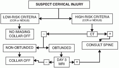
Finally, in recent years, Goergen and colleagues in Australia have integrated the conclusions from the studies mentioned earlier and have proposed a pre-imaging cervical spine injury risk stratification algorithm. Their algorithm begins with the five NEXUS criteria. If all are negative, no imaging is required. If any of the NCL criteria are present, they determine whether or not the patient needs a cranial CT examination. If not, they recommend cervical radiography. If, however, the patient requires cranial CT, they apply Hanson’s HRC. Again, if none of these are present, they recommend cervical radiography; if any of the criteria are present, they recommend cervical CT. We take issue with the use of radiography instead of CT as the first modality of imaging for reasons that will be discussed subsequently. Figure 5.1 shows our modification of Goergen’s algorithm.
Table 5.1 lists the various high- and low-risk criteria used to determine if cervical imaging is indicated for trauma.
In summary, the following are the specific circumstances under which cervical imaging should be performed following blunt trauma in the presence of any one or more of the following clinical conditions:
Hemodynamic instability
Unconsciousness
Altered mental status of whatever etiology, including the inebriated patient who falls from standing
Major craniofacial trauma
Myelopathy, radiculopathy
Major blunt trauma to the neck
Focal cervical pain and tenderness, particularly posterior and midline
Painful limitation of cervical spine motion
Proximate “distracting” injury, for example, concomitant upper rib fracture, sternal fracture, shoulder girdle dislocation, fracture, or fracture-dislocation
Major remote “distracting” injuries, for example, multiple rib fractures, major blunt abdominal trauma, and pelvic ring disruption
Figure 5.1. Algorithm for imaging evaluation of patients with suspected cervical spine injuries. CCR, Canadian C-spine rule; NEXUS, National Emergency X-Radiography Utilization Study; CT, computed tomography; MRI, magnetic resonance imaging.
TABLE 5.1 Risk Criteria For Spine Injury
High Risk
▪
Altered mental status
▪
Multiple fractures
▪
Drowning or diving accident
▪
Significant head or facial injury
▪
Age >65 years
▪
“Dangerous mechanism”
▪
Axial load to head
▪
Fall from >1 m
▪
High-speed MVC (>60 mph)
▪
MVC with large vehicle
▪
MVC with rollover, ejection
▪
Pedestrian or bicyclist struck by vehicle
▪
Crash from motorized recreation vehicle
▪
Paresthesias in extremities
▪
Rigid spine disease
▪
Ankylosing spondylitis
▪
DISH
Low Risk
▪
Canadian C-spine rule (no imaging)
▪
Absence of high-risk factors
▪
Low-risk factors that allow safe assessment of range of motion
▪
Simple rear-end MVC
▪
Sitting in ED
▪
Ambulatory at any time
▪
Delayed onset of neck pain
▪
Absent midline cervical tenderness
▪
Able to rotate neck 45 degrees left and right
▪
NEXUS criteria
▪
No midline tenderness
▪
No focal neurologic deficits
▪
No intoxication or indication of brain injury
▪
No painful distracting injuries
▪
Normal alertness
DISH, diffuse idiopathic skeletal hyperostosis; ED,emergency department; MVC, motor vehicle crash; NEXUS, National Emergency X-Radiography Utilization Study.
Isolated remote major injuries—for example, acetabular fracture, dislocated hip, fracture-dislocation of the ankle, Lisfranc fracture-dislocation — sustained in a fall or MVC capable of also producing cervical spine injuries should not be considered “distracting” injuries requiring automatic cervical spine imaging in an alert, communicative patient without cervical spine signs and symptoms.
If the patient has not sustained one of the injuries listed earlier or does not meet other high-risk criteria, imaging should not be performed.
Two other exceptions need to be mentioned. Cervical spine imaging is not indicated in patients with gunshot wounds to the cranium. In this context, it is essential to note that this distinction is restricted to gunshot (but not shotgun) wounds to the cranium (not to the face or the face and head). Patients with isolated mandibular fractures are reported to have virtually no concomitant cervical spine fractures need not be examined. Patients with other severe midface fractures should be studied.
IMAGING
Radiography
Radiography was used extensively and relied upon in the past to screen patients and to make an initial diagnosis. Multiplanar imaging was then used to confirm the initial impression and to outline the extent of damage. However, as CT and MR technology improved, radiography now has a “backseat.” However, despite the many advantages of CT, it is often necessary, in many instances, to refer to radiographs for guidance, especially for operative planning. In addition, there are still many places in the world where CT is not readily available and trauma physicians still must use radiography. For this reason, we feel there is still a role for radiography and include it in this discussion.
Techniques
Is there a “routine” series of radiographs for examining a patient with a suspected acute vertebral injury? This question is frequently asked of radiologists by our surgical colleagues. There are differing opinions of which views should be routine. The following discussion reflects our practices at large urban trauma centers that deal in significant numbers of spine injuries.
Once it has been determined that a patient needs cervical radiography, what is the least number of views required to ensure that a significant injury is not present? Most investigators agree that the absolute minimal radiographic views are the supine lateral, the anteroposterior (AP), and, where possible, the atlantoaxial (odontoid). To a great extent, the ACR Appropriateness Criteria also agrees with this premise. However, our collective experience has shown that the average trauma patient is quite large (in excess of 100 kg [220 lb]). These patients are extremely difficult to completely evaluate the cervicothoracic junction on lateral radiographs. In most instances, the supine (“trauma”) oblique views can adequately demonstrate this region. We agree with advocates of the three-view cervical series that the supine oblique views generally do not provide significant additional information about injuries. However, the ability of the supine oblique views to adequately demonstrate the cervicothoracic junction in most patients justifies its use. Our collective experience has shown that the combination of a normal AP and normal bilateral supine oblique radiographs is sufficient to adequately evaluate the cervicothoracic junction. Of course, if the patient is able to undergo cervical CT, this issue is moot.
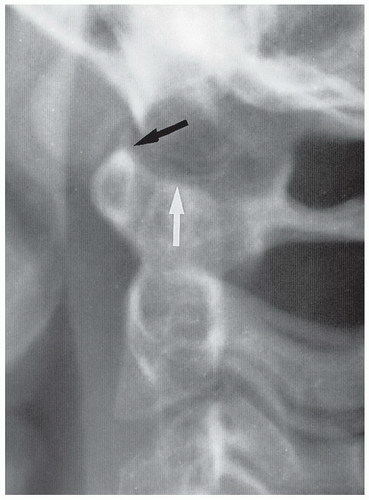
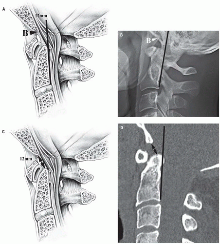
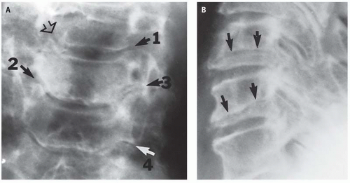
The most important cervical projection is the lateral. Gehweiler and colleagues observed at least two-thirds of significant pathology can be detected on this view. However, the surgeon and the radiologist should not rely solely on the lateral view to clear the cervical region in a trauma patient. The hazards of this practice are illustrated in Figure 5.2. From a practical standpoint, however, the presence of life-threatening injury often dictates that the patient be taken immediately to surgery before a complete cervical series can be obtained. The treatment of life-threateninginjuries always precludes obtaining a completeseries of radiographs. Once again, the speed of modern multiplanar CT renders this point moot in most instances.
In our institutions, all radiographs of the spine are obtained with the patient in a supine position. We do not turn the patient for lateral views or oblique views. A portable x-ray unit usually is adequate. Ambulatory patients may be studied in the upright position. All images are processed and displayed on our digital imaging system, where it is often possible to electronically compensate for over-exposure or underexposure.
The lateral view is obtained by means of a horizontal beam with a grid cassette. Forty-inch focal film distance is used and the cassette is placed adjacent to the patient’s head as close to the shoulders as possible. Gentle traction may be placed on the shoulders to facilitate imaging of C7. Underno circumstances should traction be applied to thehead. It may be impossible to place traction on the upper limbs in patients with upper limb fractures. Additional views with the “swimmer’s” technique may be necessary for complete imaging of the lower cervical region. If, despite all these efforts it is still impossible to see C7 and T1 in muscular or obese patients, CT with sagittal reconstruction will be necessary to clear this area. In most instances, however, the supine oblique views will be sufficient to demonstrate this region.
Once an adequate lateral radiograph has been obtained, the x-ray tube is placed in an upright position with 20 degrees of cranial angulation. The central beam is directed at the cricoid cartilage (C6). The cassette is placed under the backboard on which the patient is lying. Again, a 40-inch focal film distance is used.
The atlantoaxial region is obtained with the patient’s mouth open when possible. This projection, along with the swimmer view, is the most frequently repeated view. This view can be delayed until the patient is able to fully cooperate. It may be necessary on occasion to remove the anterior portion of the cervical collar in which the patient has arrived. To prevent motion, sandbags should be placed at either side of the patient’s head and secured with a generous amount of tape; alternatively, an assistant can hold the head. Angled views for demonstrating the arches of C1 may also be necessary.
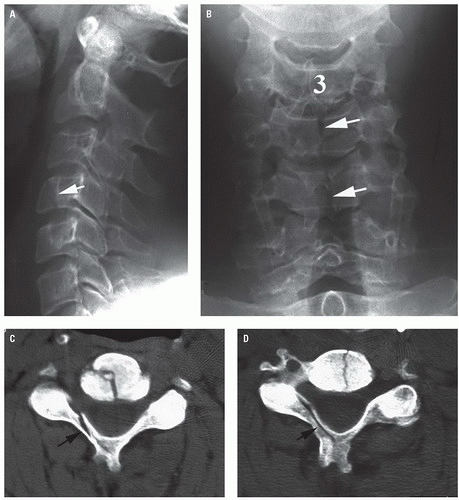
Figure 5.2. Hazards of relying on a single lateral radiograph. A: Lateral radiograph shows a fracture in the body of C4 (arrow). B: Frontal radiograph shows fractures in C4 and C5 (arrows). C and D: Axial CT images show the vertebral body fractures seen in B. However, there are also fractures in the lamina on the right (arrows).
The supine or “trauma” oblique view was developed independently at approximately the same time by Gehweiler and colleagues and Abel. For this projection, the cassette is placed flat on the table adjacent to the patient’s head and neck. The patient remains supine on the table. The x-ray tube is angled 30 to 40 degrees off the horizontal with a 15-degree cranial tilt of the tube. This cranial tilt throws the shoulders off the spine and assures that the cervicothoracic junction is demonstrable in most patients, even those with heavy shoulders. The resulting images from this technique show distortion because of the angulation. Nevertheless, the vertebral bodies, pedicles, articular pillars, and laminae are adequately demonstrated. In addition, the posterior arch of the atlas is usually visible. A pair of these oblique radiographs essentially represents two views of the same region at approximately 90 degrees to each other, preserving the cardinal principle of radiographic diagnosis— to examine an injured part with two views at 90 degrees. As mentioned earlier, a diagnosis in the lower cervical region can be made with confidence by means of a combination of the AP view and both supine oblique views.
Advocates of lateral flexion and extension radiography have recommended these studies be performed to determine whether a cervical spine injury demonstrated by radiography or by CT is “stable.” Knowledge of the pathophysiology of the cervical spine injury as reflected by the radiologic appearance of the injury, coupled by the neurologic status of the patient, should provide reasonable evidence of mechanical and/or neurologic stability. Further, mechanical instability is readily established or confirmed by CT and neurologic instability by MRI. Neither of these modalities requires motion of the cervical spine that could, in the presence of a mechanically or neurologically unstable injury, cause or aggravate spinal cord injury. We will address the issue of stability later in this chapter.
In addition, these same advocates feel that lateral flexion and extension radiographs should be reserved for patients in whom anterior subluxation (hyperflexion sprain) is suggested by the MOI (rear-end MVC) by focal posterior cervical midline pain and tenderness, by equivocal neutral lateral cervical spine radiograph, or by the concerns of the attending physician. Although some hospitals use these views routinely, we use active flexion and extension views on a limited basis. Our experience has shown these views to be of limited value in the evaluation of patients with acute trauma, usually because of muscle spasm or the inability of the patient to cooperate for an adequate study. Flexion and extension views should be reserved for patients who have minor degrees of anterolisthesis or retrolisthesis. In most cases, the cause of the listhesis is degenerative disk disease at the same level.
Flexion and extension radiography is a hands-off examination for the radiologist and the technologist. Under no circumstances should thepatient’s head be passively moved for this study. A mentally alert patient is instructed to flex and extend to the point of discomfort only. A physician should be present to supervise, primarily to tell the patient to stop moving if he or she experiences pain. In all our years of experience in ED radiology at Level I trauma centers, we know of no alert patient who has injured himself or herself performing these movements. Furthermore, there is no report in the literature of the development of significant injury when these studies are performed as described earlier. Finally, if it is absolutely necessary to determine the integrity of the cervical ligaments, MRI is the procedure of choice.
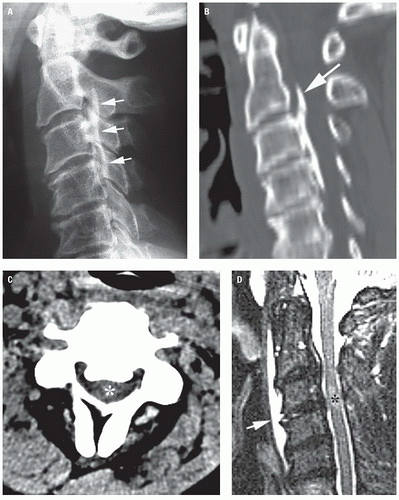
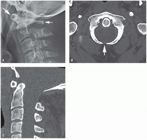
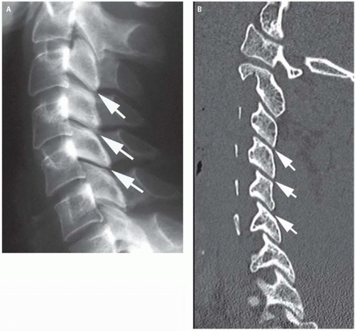
There are certain pitfalls and limitations to cervical radiography, not the least of which are the cumbersome nature of the procedure and the time needed to obtain a satisfactory examination. If it is necessary to repeat views that occurred in 79% of patients in one study, this adds to the time. Furthermore, we concur with numerous authors who have found that cervical radiographs cannot always be relied on solely to make a diagnosis. For these reasons, in our institution’s CT has replaced radiographs because of the ability of the CT examination to find more fractures in a fraction of the time a radiographic study requires. Adequate radiographic visualization of the cervicothoracic junction is frequently difficult. Muscular or obese patients present special diagnostic problems. Failing to adequately demonstrate the cervicothoracic junction presents the hazard of missing an occult fracture or dislocation (Fig. 5.3).
What about children? Radiographic examination of the cervical spine in children need not be as extensive as in adults because children do not suffer the same types of injuries that adults do. Cervical radiographs in children with suspected vertebral injury tend to fall into two categories— normal or grossly abnormal. The subtle radiographic changes found in adults are rarely present in children. Injuries commonly found in children include occipitoatlantal disruptions, atlantoaxial rotary subluxation or fixation, and occasional physeal injuries. Therefore, our institutions limit the pediatric cervical radiographic examination to lateral, AP, and open-mouth views. We do not obtain flexion or extension views on these patients. Children younger than the age of 16 years do not needCT; radiography is adequate. Those older than theage of 16 years should be studied the same way asadults, primarily with CT.
In infants and very young children, it is usually impossible to obtain a diagnostically useful open-mouth projection and, in that circumstance, the radiographic assessment of the cervicocranium must be made on the basis of the lateral (including contact lateral) examination alone. As in the adult population, the lateral radiograph of the pediatric cervical spine must include from the base of the skull through the cervicothoracic junction. Similarly, as with adults, the contour of the prevertebral soft tissues is invaluable in assessing the cervicocranium. However, unique to infants and young children are the physiologic pseudomass and physiologic pseudosubluxation of C2 and of C3. These two phenomena will be described in detail later in the chapter.
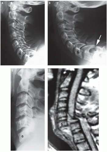
Figure 5.3. Incomplete visualization hazard. A: Lateral radiograph shows no fractures in the first 7 vertebrae. The bottom of C7 is not shown. B: Lateral radiograph repeated with traction on the arms shows dislocation of C7 on T1 with perching of the facets (arrow). C: Lateral radiograph in another patient shows no abnormalities in the six cervical vertebrae shown. D: T2-weighted sagittal MR image shows complete dislocation of C6 on C7 with severing of the spinal cord.
Clearing the cervical spine in infants and very young children, particularly those who arrive in the emergency center in cervical immobilization, is a common problem because although the vertebrae may be normally aligned and intact on the lateral radiograph, the retropharyngeal soft tissue shadow frequently appears abnormal. This soft tissue observation assumes greater significance because the child is usually screaming and it is impossible to time the lateral radiographic exposure to coincide with inspiration because of patient tachypnea. Furthermore, attending physicians are usually loath to remove the cervical immobilization to do a physical examination of the cervical spine for fear of causing damage to the cervical cord in the presence of a “radiographically unrecognized, unstable cervical spine injury.”
In this scenario, the cervical spine can be successfully assessed by remembering three salient facts. First, the incidence of cervical spine injury in pediatric patients is reported as being less than 1%; second, the likelihood of a radiographically unrecognized mechanically unstable cervical spine injury is exceedingly rare; and third, it is common knowledge that infants and very young patients demonstrate, for example, pyarthrosis or osteomyelitis of the lower extremity by failing to use that extremity. Under the clinical and radiographic circumstances described earlier, Swischuk advocates having a physician or nurse gently hold the patient’s head in neutral position while the cervical spine immobilization is removed. Simultaneously, the infant’s head is released by the nurse or physician. In the absence of a cervical spine injury, the infant, happy to be free of the immobilization, will voluntarily look around the room by moving the head and cervical spine, thereby clinically clearing the cervical spine. Conversely, in the rare instance of radiographically unrecognized cervical spine injury, the infant will not move the head or neck because of pain and muscle spasm. In that instance, immobilization should be reestablished and the patient sent for MR examination of the cervical spine.
Computed Tomography
CT is now the imaging modality of choice for examination of the cervical spine. Although the technology was developed in the 1970s, cervical CT was initially reserved for the following situations: equivocal conventional radiographic examination, inability to clear the cervicocranium and/or the cervicothoracic junction clinically or by conventional radiography, all fractures involving the spinal canal, and all fracture-dislocations. In the 1990s, however, investigators began recognizing the value of using CT as a primary tool for identifying cervical fractures. Borock and colleagues, in 1991, using CT as an adjunct to the three-radiograph cervical spine series for indications similar to those cited earlier found that CT demonstrated 98% of injuries. Furthermore, the combination of the radiographic study and CT detected 100% of cervical spine injuries.
Shortly thereafter, Blacksin and Lee recommend CT for evaluation of the cervicocranium in patients in whom the open-mouth projection is not possible. Another study found that CT of the cervicocranium as a caudal extension of head CT in pediatric patients less than 6 years of age to be diagnostic in 91% of examinations compared with only 9% of openmouth projections of the same patient population, and they recommend CT of the cervicocranium as part of the initial radiographic evaluation of the upper cervical spine in young pediatric patients. Throughout the remainder of the 1990s and early years of the new millennium, there were increasing numbers of papers recommending CT be performed instead of radiography.
CT was shown to not only be effective in demonstrating fractures, it could do so in as much as half the time as that required for a conventional radiographic study. And time to a trauma surgeon is golden. During the same period, the technology changed, first with helical CT and then with multidetector scanning. Both of those technology advances reduced the time necessary to perform a CT examination of the cervical spine.
Today, multidetector CT (MDCT) using 16-, 64-, and sometimes 256-detectors reduces the time of scan to mere seconds, significantly reducing motion artifacts. In addition to the rapid scan time, MDCT allows for excellent multiplanar and three-dimensional (3D) reconstruction has resulted in improved diagnoses of vertebral injuries.
Vertebral CT is easy to perform. In our trauma centers, we routinely obtain the cervical scan at the same time the patient undergoes a cranial scan. The cervical images are reconstructed from the data set at a thinner slice thickness than that for the brain. Summers and Galli have shown, using the Visible Human database (Visible Human Project, National Library of Medicine), that conventional CT with 5-mm cut intervals missed as many as 75% of cervical spine fractures and that 3-mm cut intervals demonstrated 100% of all but the smallest fractures. Other authors recommend cut intervals of 1.5 to 2.0 mm through the cervicocranium and 3-mm intervals through the lower cervical and cervicothoracic spine.
Our standard procedure on our 64-slice MDCT for a cervical scan is to obtain contiguous 2 mm slices from the skull base to the bottom of T1 or T2. Two-millimeter axial images are reconstructed from the data in both bone and soft tissue windows (Fig. 5.4). In addition, sagittal and coronal multiplanar images are also reconstructed from the data set. We find the sagittal reconstructed image is most useful for a macroscopic evaluation of all levels of the spine. If necessary, the data set can be revisited to reconstruct 1 mm slices for small fractures. However, we rarely find this necessary. We do not routinely use intravenous contrast enhancement unless a CT angiogram is ordered.
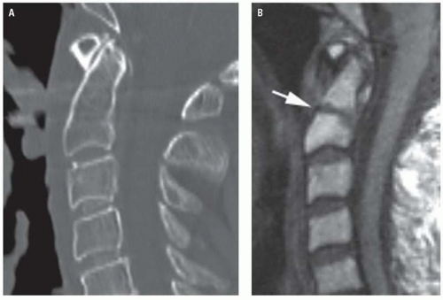
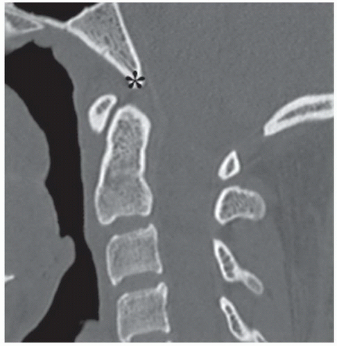
Figure 5.4. Value of viewing CT images at bone and soft tissue windows. A: Saggital reconstructed CT image shows a dens fracture (arrow) with slight retrolisthesis. B: Axial image at bone window shows the fracture (arrows). C and D: Axial images at soft tissue window shows an associated epidural hematoma (arrows).
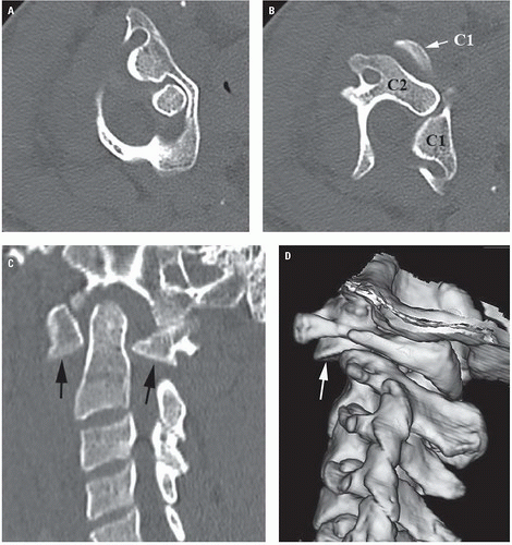
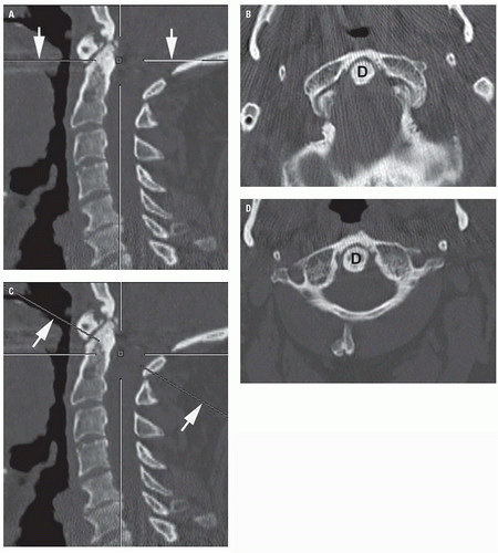
The 3D volumetric CT reformation is infrequently used in the initial evaluation of acute blunt spinal trauma. The value of 3D CT is derived largely from the display of spatial relationships of the vertebra and of fragment alignment for treatment planning and teaching purposes. We have found it most useful for demonstrating atlantoaxial dislocations (Fig. 5.5).
Figure 5.5. Rotary dislocation of C1 on C2 showing value of 3D reconstruction. A: Axial CT image shows C1 rotated to the left. B: Axial image slightly lower shows the degree of rotation of C1 on C2. C: Sagittal reconstructed image shows the dislocated inferior facets of the lateral masses of C1 (arrows). D: 3D reconstructed image adds perspective to the dislocated facet (arrow).
Figure 5.6. Ossification of the posterior longitudinal ligament (OPLL) with cord injury. A: Lateral radiograph shows the dense ossification of the posterior longitudinal ligament (arrows). B: Sagittal reconstructed CT image shows the extent of canal compromise (arrow). C: Axial image at soft tissue window shows compression of the thecal sac (asterisk). D: Sagittal Short Tau Inversion Recovery (STIR) image shows central cord edema (asterisk). Note the fluid collection anteriorly (arrow).
Scout views are obtained to determine the level of the scan. In the cervical region, they are performed in the lateral position. Enlarged scout images are displayed with and without level annotations.
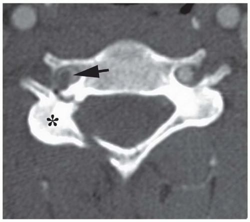
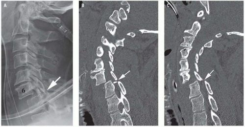
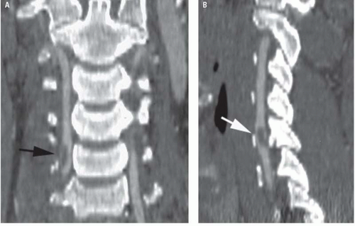
CT provides detailed information about the extent of injury. In addition to being the best method for demonstrating canal (Fig. 5.6) or intervertebral foramen encroachment (Fig. 5.7), it is also useful for identifying fractures of the laminae, pedicles, and articular pillars. It is especially useful for showing fractures that accompany perched or locked facets (Fig. 5.8).
Figure 5.7. Transverse foramen involvement in a patient with fractures of the pedicle and lamina. Axial image shows rotation of the right articular pillar (asterisk). Note the hematoma in the right vertebral artery (arrow) compared with the normal left artery.
Most imaging in the United States is performed by digital means using picture archiving and computer storage (PACS). This sophisticated computer technology allows us to manipulate data to improve images, giving us the ability to darken or lighten images or to shift data to improve demonstration of certain areas. This has become particularly useful when reviewing images on patients who are not lying perfectly straight in the CT gantry (Fig. 5.9).
CT has enabled us to evaluate two regions that posed significantly difficult diagnostic problems in the past— the craniovertebral and the cervico-thoracic junctions. The reasons for this difficulty related to the inability of the open-mouth and the lateral radiographs to adequately demonstrate the craniocervical junction. The cervicothoracic junction posed additional difficulties because of patient size and the frequent overlap of shoulders over the area. Craniocervical junction fractures, specifically of the occipital condyles were once considered rare. Cervicothoracic junction fractures are notoriously difficult to see on radiographs. However, CT demonstrates these areas not only on axial views but also on the sagittal and coronal multiplanar reconstructed images.
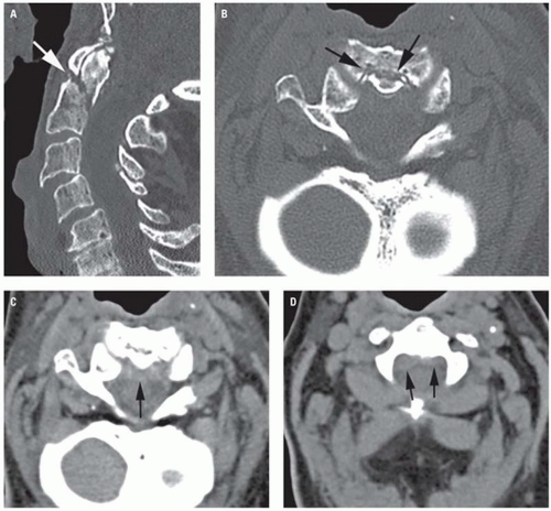
CT angiography (CTA) is a useful adjunct to cervical CT, used primarily for patients with fractures that involve the transverse foramina and who are suspected of having injury or occlusion to the vertebral artery. It is also useful for patients with penetrating injuries to the neck to determine the integrity of the carotid arteries. These studies are obtained separately from the routine cervical scan. Typically, the study is performed from the level of the orbits to the aortic arch (as determined from an AP scout view). A 100 mL of nonionic contrast is injected intravenously at a rate of 3.5 to 4 mL/sec. Scanning at 2 mm intervals starts 12 to 18 seconds after the injection begins and the images are reconstructed at 1 mm. In addition, sagittal and coronal, as well as 3D volumetric reconstruction, is performed for interpretation (Fig. 5.10).
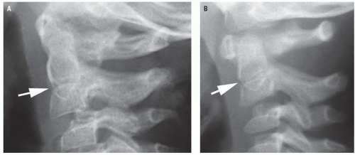
Figure 5.8. Bilateral facet lock C6-C7. A: Lateral radiograph shows anterolisthesis of C6 with malalignment of the facets (arrow). B and C: Sagittal reconstructed images show the point of locking (arrows).
Figure 5.9. Image manipulation feature of digital imaging system. A: Sagittal reconstructed CT image shows orientation of the original scan (arrows). B: Axial image through C1 and the tip of the dens (D) at the level shown in A. C: Sagittal image shows a shift of the orientation line (arrows) following manipulation. D: Axial image now shows the entirety of C1. (From Daffner RH. Imaging of Vertebral Trauma. 3rd ed. Cambridge, United Kingdom: Cambridge University Press; 2011, with permission.)
In many institutions, CT may be combined with myelography to evaluate traumatic encroachment of the subarachnoid space and spinal cord by bone fragments or herniated intervertebral disk fragments (Fig. 5.11). CT myelography is also useful for studying cervical nerve root avulsions (Fig. 5.12) and, on occasion, posttraumatic cystic myelopathy. As a rule, MRI is preferred for those indications; however, CT myelography is performed because MRI is either unavailable, the patient is too unstable, or the patient has a contraindication such as a cardiac pacemaker.
Figure 5.10. CT angiogram showing a clot in the vertebral artery on the right (arrows). A: Coronal, (B) sagittal reconstructed images. Same patient as in Figure 5.7.
Figure 5.11. CT myelogram in a patient with a burst fracture. A: Sagittal reconstructed image shows a displaced bone fragment (asterisk) in the vertebral canal. B: Axial image shows effacement of the column of contrast (arrows) by the fragment. (From Daffner RH. Imaging of Vertebral Trauma. 3rd ed. Cambridge, United Kingdom: Cambridge University Press; 2011, with permission.)
Figure 5.12. CT myelogram snowing nerve root avulsion. A: Coronal reconstructed image shows contrast filling the sheath of the avulsed nerve root on the left (asterisk). Note the appearance of the normal roots (arrows). B: Axial image shows filling of the nerve sheath on the left (largearrow) and extravasation of contrast into the epidural space (small arrow). (From Daffner RH. Imaging ofVertebral Trauma. 3rd ed. Cambridge, United Kingdom: Cambridge University Press; 2011, with permission.)
CT has several pitfalls and limitations. Patient-related problems result primarily from motion, patient size, and artifacts caused by dental fillings and metallic implants. Motion produces blurred images and engenders the possibility of a missed diagnosis. Motion can also disrupt multiplanar reconstructions, in many instances, simulating a fracture. Fortunately, motion artifacts are easily identified on the axial images. On sagittal and coronal reconstructed images, the artifact frequently produces a linear shift in data in the surrounding tissues. When in doubt, repeating scan, referral to the scout view, or to radiographs may solve the dilemma.
The patient’s weight and size are also sources of arti facts. Most modern CT machines have a patient weight limit of 400 to 450 lb because the table must project into the gantry for the examination. Large patients frequently contact the ring of the scanner and this produces streak artifacts that can hide underlying pathology. Dental fillings or other metallic implants (e.g., joint replacements, rods, hooks, screws, plates, vascular clips, bullet fragments) produce streak artifacts that severely compromise the CT image. Many of the new scanners have metal-supression software that can reduce these artifacts. Furthermore, changing the window setting on the viewing monitor may alleviate some of these problems.
There are three technical pitfalls that can compromise the information being obtained from the CT examination. These are the partial volume averaging effect, poor level calibration, and fractures in the plane of the scan. The partial volume-averaging effect is a well-known CT phenomenon. Normally, CT results in an image that represents an average of the radiographic densities of all structures contained within that section of tissue. Any normal structure that is not completely located within that plane may be distorted or totally discarded from the final image.
Fractures are usually seen on more than one cross- section. It is possible, however, particularly when imaging thin structures such as the laminae or posterior arch of C1, that a fracture is demonstrated on one view only. Furthermore, normal overlap of structures from adjacent vertebrae occurs, lines of interruption will be apparent in the bony shadow, which could be misinterpreted as fractures. This is most often a problem in the cervical region because of the small size of adjacent vertebrae.
On some older CT machines, an annotation discrepancy on the scout view can result in erroneous information being obtained about the level of injury. This, generally, does not present a significant problem when knowledge of anatomy (dens, ribs, sacrum) is used to determine the levels of fracture.
Fractures that are oriented in the horizontal plane, particularly of the dens or body of C2, may not always be demonstrated by CT. We can overcome this pitfall by tilting the gantry to place the fracture out of the plane of the scan. In some cases, however, it will be necessary to resort to reviewing the scout view or to radiography to identify the fracture.
Magnetic Resonance Imaging
MRI is an indispensable tool for diagnosing of a broad spectrum of vertebral and spinal cord pathology as well as the sequelae of trauma. Although radiography and CT reveal important details about fractures and abnormal alignment, MRI is unique in its depiction of all aspects of intrinsic spinal cord injury, fractures (overt and occult), and ligament injuries. Spinal cord compression by bone fragments, disk herniation, and epidural or subdural hematomas can also be diagnosed. Serial examinations can also reveal the onset of posttraumatic progressive myelopathy secondary to hemorrhagic cord contusion. Furthermore, refinement of MR angiography (MRA) has provided adjunctive information about vertebral artery dissection or occlusion. Finally, we are using MRI to “clear” the spine in patients who remain comatose for 48 hours.
MRI is also recommended in patients with acute traumatic radiculopathy such as occurs in scapulothoracic dissociation. Although the root avulsion may not always be demonstrated, secondary signs of avulsion such as pseudomeningocele or contralateral displacement of the cervical cord may be found.
Another benefit of MRI, when supplementing spinal CT, is significantly reducing the need for myelography. The risks associated with myelography are increased in the setting of acute trauma. We now reserve (CT) myelography for cases in which MRI is contraindicated, where the patient is hemodynamically unstable, where the technical challenges of the MR examination result in suboptimal image quality, or for parts of the world where MRI is unavailable.
A discussion of MR technique requires both an understanding of the logistics involved in the scanning of acutely injured patients in a safe manner and knowledge of the appropriate pulse sequences to achieve diagnostic efficacy.
Patient safety during MRI is a major concern. The MRI suite should have the capacity for video and audio observation of the patient. Verbal interaction is desirable for patients able to speak. For those who cannot communicate because of anesthesia, sedation, or the nature of their injury, physiologic monitoring is imperative to assure that hemodynamic stability is maintained. Nursing personnel should be allowed to stay in the MR suite close to the patient.
The Safety Committee of the International Society of Magnetic Resonance as well as the ACR and the American Society of Neuroradiology have made recommendations regarding patient safety during MR studies. MRI facilities that have been accredited by the ACR follow these guidelines. Monitoring is strongly recommended for sedated as well as alert patients. Electrocardiographic, blood pressure, and blood oxygenation by pulse oximeter monitoring should also be performed, and the readings should be displayed within the control room. Care must be taken to prevent thermal injury on monitored patients by avoiding coiled or looped wires in which electrical current can be induced. This is particularly important in patients with sensory deficits who cannot feel the heat.
Patients with a known history of metalworking, surgical prosthesis implantation, or shrapnel/bullet wound should be carefully screened with radiographs before undergoing an MR examination. Any potentially retained or implanted metallic object must be either proved MR compatible using available resources (http://www.imrser. org) or visualized using radiography, and should be remote from vital structures. Ferromagnetic metallic objects in close association to sensitive structures can have disastrous complications when exposed to the strong magnetic fields of the MRI magnet because of local motion or thermal effects.
One of the advantages of MRI is the availability of an almost limitless menu of scanning parameters. A discussion of the specific scanning sequences is beyond the scope of this chapter. However, a few words on them is appropriate. Short TR spin echo sequences have remained essential components of the examination to show the alignment of the vertebral axis in the midsagittal plane and to assess and the external morphology of the spinal cord. These sequences are also useful for demonstrating alteration of vertebral body marrow signal because of compression fractures and can reveal signal abnormalities that indicate hemorrhage, particularly in the subacute time frame. This is also particularly useful for finding additional “occult” injuries (Fig. 5.13). Acute hemorrhage is best demonstrated on either T2-weighted gradient echo sequences or fast or turbo spin echo T2-weighted sequences. In general, these sequences achieve a 50% to 70% decrease in time of study, with a consequent reduction of motion artifacts. Although fast spin echo sequences are slightly less sensitive to the magnetic susceptibility effects of acute hemorrhage, they help to minimize artifact that can occur when metallic fixation devices are present. A gradient echo sequence in a complementary (usually axial) plane is a practical option to improve sensitivity to hemorrhage.
Short Tau Inversion Recovery (STIR) is a fat suppression technique where the signal of fat is zero. In comparison to conventional spin echo, fat signal is darkened. Body fluids have both a long T1 and a long T2. Consequently, STIR is extremely sensitive for detection of edema.
We use the following scanning parameters for cervical spine injury:
Sagittal T1-weighted spin echo
Sagittal turbo T2-weighted spin echo
Sagittal STIR
Axial T1-weighted spin echo
Axial gradient echo (GRE)
As with any diagnostic study, there are pitfalls for MRI. First and foremost is the patient who is too hemodynamically unstable to allow scanning. Second are patients with implanted devices such as pacemakers, defibrillators, cochlear implants, as well as patients with ferromagnetic foreign bodies.
Patient Condition and Cervical Spine Imaging
The applications of the various imaging modalities to the evaluation of patients suspected of having sustained blunt cervical spine trauma is governed by the condition of the patient. Patients with suspected cervical spine injury may be assigned to one of four classes based on clinical status as follows: (1) clinically stable without cervical neurologic deficit, (2) clinically stable with cervical neurologic deficit, (3) clinically unstable but neurologically intact (multiple trauma, polytrauma), and (4) clinically unstable with neurologic deficit. Patients in the first category should be screened using the Canadian rules. If the patient is alert and there are no high-risk parameters, no imaging needs to be performed if the patient can actively flex and extend and rotate his or her neck. Patients in all other categories should undergo cervical CT. Those with neurologic deficits should also undergo cervical MRI as soon as practicable.
Figure 5.13. Radiographically occult dens fracture demonstrated by MRI. A: Sagittal reconstructed CT image is normal. B: T1-weighted sagittal MR image shows a horizontal fracture through the dens. This fracture was in the plane of the CT scan and could not be demonstrated.
RADIOGRAPHIC ANATOMY
No discussion of this type would be complete without a brief review of the anatomic structures contributing to the overall physiology and stability of the cervical spine. The mechanical stability of the entire spine with the exception of the cervicocranium is maintained by both ligamentous and osseous structures.
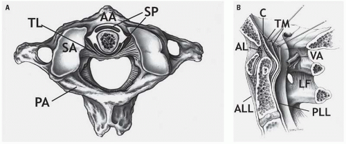
The ligamentous structures of the cervicocranium include, in addition to the occipitoatlantal and atlantoaxial articular joint capsules, from anterior to posterior, the upward extension of the anterior longitudinal ligament (ALL), which is the atlantoaxial ligament (from C2 to C1) and its further upward extension, the anterior atlantooccipital membrane (from the anterior arch of C1 to the anterior margin of the foramen magnum), the dentate ligament (apical ligament of the dens), the cruciform ligament and the upward extension of the posterior longitudinal ligament, the tectorial membrane (Fig. 5.14A), the alar “check” ligaments that extend from the tip of the dens to the occipital condyles, and the transverse atlantal ligament (the horizontal fibers of the cruciform ligament) (Fig. 5.14B). The transverse atlantal ligament extends between the lateral masses of C1 and, passing posterior to the dens, articulates with the dens by a true synovial joint. The transverse atlantal ligament maintains the normal relationship between the dens and the anterior tubercle of C1, that is, the anterior atlantodental interval (AADI). Within the cervicocranium, mechanical stability is maintained by the very dense ligaments identified earlier. The cervicocranial skeleton contributes very little to structural stability, there being no skeletal structures comparable to the articular masses of the lower segments.
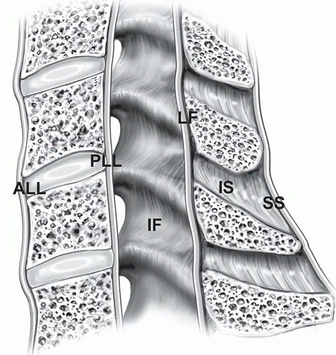
The ligaments of the lower cervical spine include the ALL, the posterior longitudinal ligament (PLL), and the posterior ligament complex (PLC), which includes the capsule of the apophyseal joints, the ligamentum flavum (the yellow ligament), and the interspinous and supraspinous ligaments (Fig. 5.15), as well as the intervertebral disks. The skeletal contribution to mechanical stability derives from the normal anatomic relationship of the articular masses as they form the apophyseal (interfacetal) joints.
Figure 5.14. Occipitoatlantoaxial ligaments. A: Atlantoaxial joint from above. AA, anterior arch of atlas; PA, posterior arch of atlas; SA, superior articular facet of atlas; SP, synovial pads; TL, transverse ligament. B: Sagittal section of craniovertebral junction. AL, apical ligament of dens; ALL, anterior longitudinal ligament; C, cruciform ligament; LF, ligamentum flavum; PLL, posterior longitudinal ligament; TM, tectorial membrane; VA, vertebral artery. (From Daffner RH. Imaging of Vertebral Trauma. 3rd ed. Cambridge, United Kingdom: Cambridge University Press; 2011, with permission.)
Figure 5.15. Schematic view of vertebral ligaments. ALL, anterior longitudinal ligament; IF, interfacetal ligament; IS, interspinous ligament; LF, ligamentum flavum; PLL, posterior longitudinal ligament; SS, supraspinous ligament.
The cervicocranium differs greatly anatomically, morphologically, and physiologically from the lower cervical spine. Thus, the radiographic anatomy of each is presented separately.
Cervicocranium
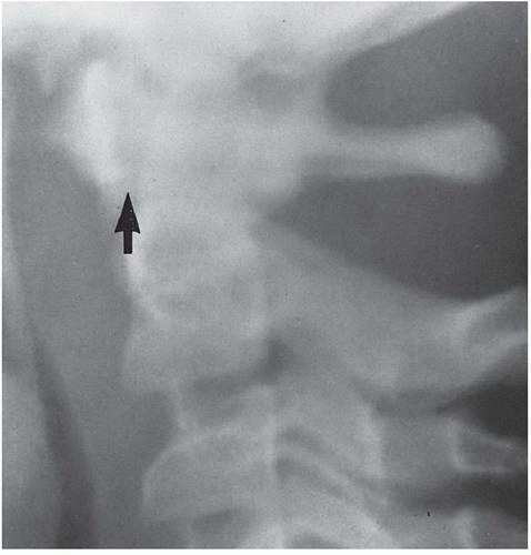
The skeletal components of the cervicocranium include the margins of the foramen magnum, the occipital condyles, and the atlas and axis vertebrae. The clivus is formed by fusion of the posterior portion of the body of the sphenoid with the basilar portion of the occipital bone at the sphenoccipital synchondrosis (Fig. 5.16). The synchondrosis may normally remain visible on radiographs and sagittal CT images until early adulthood and should not be misinterpreted as a fracture. The tip of the clivus, the basion, is a very important radiologic landmark visible on virtually all lateral radiographs, and, of course, on sagittal reconstructed cervical images of adults and children (Fig. 5.17). The relevance of the basion is its role in the recognition of occipitoatlantal dissociation, which is discussed subsequently.
Figure 5.16. Normal spheno-occipital synchondrosis (arrows).
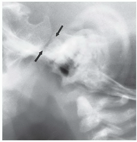
The convex occipital condyles articulate with the medially oriented, biconcave superior articular surfaces of the lateral masses of C1 (Fig. 5.18). Whereas the occipitoatlantal articulation is occasionally not visible on the open-mouth radiograph of the atlantoaxial articulation, it is clearly demonstrated by panoramic zonography (Fig. 5.19) and by multiplanar CT (see Fig. 5.18). In infants and young children, the occipital condyles may normally be visible on the lateral cervical spine radiograph (Fig. 5.20) because the condyles are not yet obscured by the physiologically underdeveloped mastoid processes and lateral masses of C1. However, it is very important to realize that the occipitoatlantal articulation is not normally visible on the lateral radiograph of adolescents or adults because of the overlap of the mastoids. This is one reason occipital condyle fractures (as well as lateral mass fractures of C1) were considered rare in the days before CT began being used as the main screening tool.
Figure 5.17. Sagittal reconstructed CT image showing the normal basion (asterisk) at the tip of the clivus. This structure is much easier to see on CT than on lateral radiographs.
Figure 5.18. Normal occipitoatlantal junction as shown on coronal reconstructed CT image.
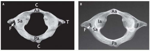
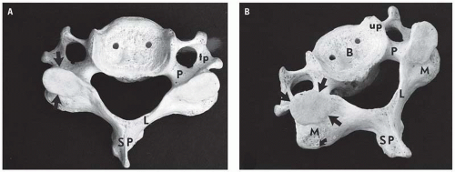
The atlas vertebra (C1) (Fig. 5.21) is a ring-like bone with an anterior arch (and tubercle), bilaterally large lateral masses from which arise the short transverse processes, and a posterior arch (and tubercle). C1 differs from all other vertebrae in that it does not have a body. C1 articulates with the dens through the interposed true synovial joint. From a purely semantic standpoint, C1 is the only vertebra withlateral masses. The analogs in the other cervical vertebrae are the articular pillars (see the following texts). Anomalies, such as failure of fusion of the posterior or anterior arches, or partial or complete agenesis of the posterior arch of the atlas occur. Of these, failure of fusion of the posterior arch is the most common. It can be recognized on a lateral radiograph as absence of the spinolaminar line (see below) at C1, and as a cleft in the arch on an axial CT image (Fig. 5.22). This anomaly has smooth, rounded borders that do not fit together like pieces of a jigsaw puzzle, the way fractures would. When encountered, the finding should be mentioned in the report on the study as a normal variant. Anomalies of the ring of C1 usually result in hypertrophy of the anterior arch, a response to increased stress placed on that structure.
Figure 5.19. Normal occipitoatlantal articulation (arrows) as shown by panoramic zonography.
Figure 5.20. Normal craniocervical junction of a 5- year-old child. Note the physiologic pseudosubluxation of C2 with respect to C3.
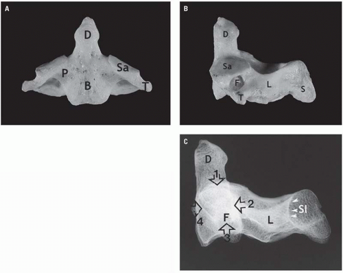
Like the atlas (C1), the axis (C2) is morphologically distinct from all other vertebrae in the upward extension of its body into the dens and by the absence of clearly defined pedicles (Fig. 5.23).
In approximately 20% of patients younger than the age of 8 years, the anterior arch of the atlas appears to lie above the tip of the dens (Figs. 5.24 and 5.25). This is partly because of the physiologic laxity of the cervicocranial soft tissues and partly because the tip of the dens is not ossified in infants and young children. This normal relationship should not be misinterpreted as atlantoaxial dislocation or subluxation.
Figure 5.21. Atlas vertebra as viewed from above. A: Anatomic specimen. B: Radiograph. Aa, anterior arch; C, central tubercles; F, transverse foramen; IA, inferior articular facet; Pa, posterior arch; Sa, superior articular facet; T, transverse process. (From Daffner RH. Imaging of Vertebral Trauma. 3rd ed. Cambridge, United Kingdom: Cambridge University Press; 2011, with permission.)
Figure 5.22. Failure of fusion of posterior arch of atlas. A: Lateral radiograph shows absence of the spinolaminar line of the atlas (small arrow) and hypertrophy of the anterior arch (large arrow). B: Axial CT image shows the cleft in the posterior arch (arrow). C: Sagittal midline CT image shows no posterior arch.
Figure 5.23. Axis vertebra. A: Frontal view of specimen. B: Lateral view. B, body; D, dens; F, transverse foramen; L, lamina; P, pedicle, Sa, superior articular facet; T, transverse process. C: Lateral radiograph showing Harris’ ring. (1) Superior articular facet; (2) posterior body line; (3) transverse foramen (T); (4) anterior body line. D, dens; Sl, spinolaminar line (arrowheads). (From Daffner RH. Imaging of VertebralTrauma. 3rd ed. Cambridge, United Kingdom: Cambridge University Press; 2011, with permission.)
Figure 5.24. Lateral radiograph of the craniovertebral junction in an infant showing the superior margin of the anterior tubercle of C1 (arrow) rostral to the tip of the dens (arrow head) and the occipital condyles (open arrow). The lobulated mass (asterisk) is adenoidal tissue.
Figure 5.25. Nine-year-old child in whom the superior portion of the anterior tubercle of C1 (black arrow) is normal rostral to the tip of the dens (white arrow).
Figure 5.26. Axis ossification centers and synchondroses. (From Daffner RH. Imaging of Vertebral Trauma. 3rd ed. Cambridge, United Kingdom: Cambridge University Press; 2011, with permission.)
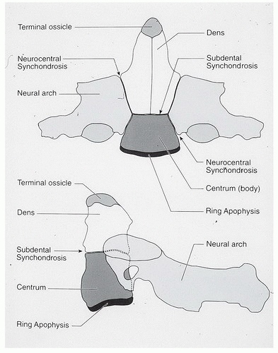
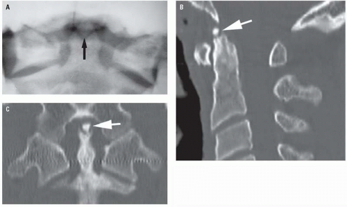
The axis vertebra (C2) arises from several separate ossification centers (Fig. 5.26), some of which have radiographic relevance. During infancy and before the apophysis of the tip of the dens ossifies, the rostral-most portion of the dens has a V-shaped configuration on the AP radiograph (Fig. 5.27A). Should the terminal apophysis fail to unite, the resultant separate ossicle is called the os terminale (Figs. 5.27B and C).
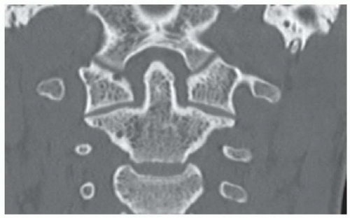
The subchondral (subdental) synchondrosis lies between the base of the dens and the axis body and appears as a normal horizontal lucent defect in the axis body on the lateral radiograph of the cervicocranium of infants and young children (Fig. 5.28). This synchondrosis, like others of the axis, fuses between the 3rd and 6th years of life. The subchondral synchondrosis may persist as a pair of thin, sclerotic parallel densities that are the “scar” of the synchondrosis that should not be misinterpreted as an incomplete or impacted fracture.
The neurocentral synchondrosis (see Fig. 5.26) is usually seen only on oblique projections of the pediatric cervical spine. This synchondrosis, clearly depicted by CT (Fig. 5.29), should be distinguished from acute fractures by its location and imaging characteristics. Further, acute fractures of the axisbody are extremely rare in infants and young children. To reiterate, neither the subchondral nor the neurocentral synchondroses should be mistaken for a fracture.
Figure 5.27. V-shaped dens tip with accessory ossicle. A: Open-mouth radiograph shows the V-shaped dens containing the accessory ossicle (arrow). B: Sagittal and (C) coronal reconstructed CT images show t erminal ossicle (arrows).
Figure 5.28. Subdental synchondrosis (arrows) in two infants. This is a normal finding.
Figure 5.29. Normal neurocentral synchondroses of C1 (large arrows) and C2 (small arrows).
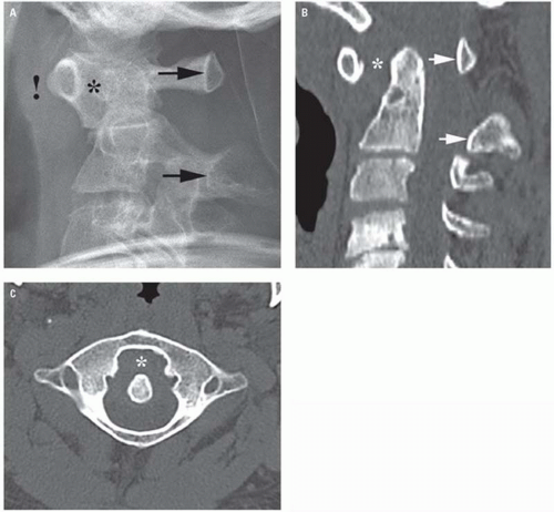
The distance between the anterior surface of the dens and the posterior surface of the atlas tubercle is the AADI, also called the predental space. In infants and children, until the age of approximately 8 years, the AADI varies in width with flexion and extension but it usually does not exceed 5 mm. Additionally, in infants and young children, it is common for the AADI to have a V-configuration in neutral and flexion lateral projections (Fig. 5.30). In extension, the contiguous surfaces of the AADI become congruous. This change in configuration of the AADI is caused by the physiologic laxity of the transverse atlantal ligament normal in patients of this age. In adults, because of the maturity of the transverse atlantal ligament, the AADI remains constant during flexion and extension (Fig. 5.31) and does not normally exceed 3 mm with a 40-cm target-radiograph distance. The most common cause of widening of this interval in adults is rheumatoid arthritis (Fig. 5.32).
Figure 5.30. Normal AADI (arrow) in a child. This space should never exceed 5 mm. The V-shaped predental space is a normal variant, found in approximately 15% of individuals.
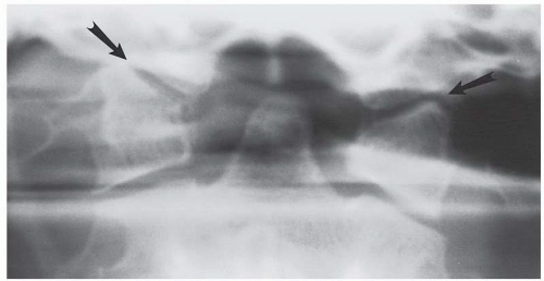
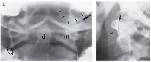
The frontal and lateral projections of the atlantoaxial articulation provide different but equally useful information. The frontal (open-mouth) projection (Fig. 5.33A) shows the normal atlantoaxial relationship in the coronal plane, where, traditionally, the important findings are the lateral atlantodental interval, the configuration of the lateral masses of C1, the relationship of the lateral margins of the contiguous facets of C1 and C2, and the position of the bifid spinous process of C2. However, if the open-mouth projection does not include the occipital condyles and the occipitoatlantal articulation, it is an inadequate study and therefore precludes clearing of the cervicocranium radiographically. This issue is moot when CT is used as the prime screening imaging modality.
Figure 5.31. Normal AADI (asterisk) in an adult. This space should never exceed 3 mm.
Figure 5.32. Wide AADI (asterisk) in a patient with rheumatoid arthritis. A: Lateral radiograph shows, in addition to the wide predental space, a shift in the alignment of the spinolaminar line (arrows). Note the prevertebral soft tissue swelling (!) caused by pannus proliferation. B: Sagittal reconstructed and (C) axial CT images show the same findings.
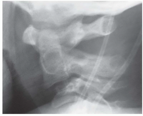
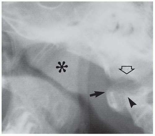
Figure 5.33. Normal craniocervical junction in an adult. A: A properly positioned open-mouth view must include the occipital condyles (small arrows), the occipitoatlantal articulation (largesolid arrow), the lateral masses of C1 (m), the dens (d), the atlantoaxial joint spaces (open arrow), and the superior portion of the axis body. The space between the dens and the lateral mass of C1 is the lateral atlantodental interval, which may vary in width. Normally, the corners of the contiguous facets of C1 and C2 should be on the same vertical plane plus or minus 2 mm (whitelines). B: Lateral radiograph shows a normal AADI (arrow). The prevertebral soft tissue shadow (asterisk) is normal.
The lateral projection (Fig. 5.34) shows the normal relationship of the basion to the posterior axialline (PAL), the upward extension of the posterior cortex of the axis body. This line allows is critical for identifying disruptions of the occipitoatlantal joint, using two simple measurements. The basion-axial interval (BAI) is the distance between the PAL and the basion (Figs. 5.34A and B), and should not be less than 6 mm or not more than 12 mm in adults or children. The measurement is the same on radiographs as well as on saggital reconstructed CT images. The BAI is reliable, even in the presence of anomalies of the posterior elements of the atlas and axis, inclination of the dens, and variations in the slope of the clivus. It is not affected by flexion or extension.
A second measurement, the basion-dens interval, is the distance between the basion and the tip of the dens (Figs. 5.34C and D). Conveniently, the maximum distance in adults and children older than the age of 13 years is also 12 mm. Unfortunately, the basion-dens interval measurement is not accurate in children younger than 13 years of age because of incomplete ossification and fusion of the dens. This measurement is also valid on both radiographs as well as on sagittal reconstructed CT images.
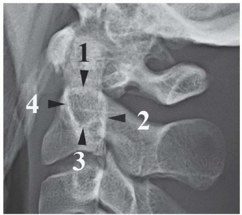
There is another important landmark on the lateral radiograph referred to as Harris’ ring. This “ring” appearance is not from an actual structure. It results from the overlap of the images of several portions of the body of the axis. The ring is the result of the phenomenon of subjective contours and each of its four arcs derives from four different parts of C2. The upper arc represents the superior articular facets, the anterior arc represents the anterior body cortex and the pedicle, the inferior arc represents the lower margin of the transverse foramen, and the posterior arc represents the posterior vertebral body line (PVL) (Fig. 5.35). Harris’ ring can only be seen on radiographs and not on CT images because the contours are perceived (hence subjective) rather than based on a real structure.
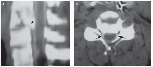
There is a final relationship regarding the axis to its mates that had greater importance in the diagnosis of occult cervical fractures in the days before CT was the main screening modality. This was originally described by Smoker, who noted that the AP width of the body of C2 should be the same as C3. She observed that subtle fractures of the body of C2 frequently widened the vertebra and she called the sign the “fat C2” sign. The use of CT to routinely screen for cervical injuries has relegated this sign to a historic curiosity.
Figure 5.34. Dens-basion line. Normally, the basion (B) should be not less than 6 mm nor more than 12 mm in front of a line along the posterior body of C2. A: Drawing. B: Lateral radiograph. C and D: Dens-basion interval. The tip of the dens should be no further than 12 mm from the basion. C: Drawing. D: Sagittal CT image. These measurements are valid on radiographs as well as on CT images.
Figure 5.35. Harris’ ring. Lateral radiograph showing the four components of the “ring”: (1) superior articular facet; (2) posterior body line; (3) inferior margin of transverse foramen; (4) anterior body line. (From Daffner RH. Imagingof Vertebral Trauma. 3rd ed. Cambridge, United Kingdom: Cambridge University Press; 2011, with permission.)
The atlantoaxial joint permits flexion, extension, rotation, vertical approximation, and lateral bending (gliding). The maximum allowable motion in flexion and extension at that level is about 20 degrees, the maximum allowable rotation is 45 degrees, and the maximum allowable lateral flexion is 5 degrees. Interestingly, the fact that motion occurs along all three (X, Y, and Z) axes accounts for the predominance of cervical injuries at this level in the elderly. The reason for this is the fact that the C0-C2 region remains the most mobile portion of the cervical spine as aging produces arthritis at lower levels.
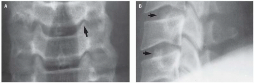
Both rotation and lateral bending (lateral tilt of the head with respect to the cervical spine) physiologically produce asymmetry of the lateral masses of C1 with respect to the dens as well as asymmetry between articulating surfaces of the lateral masses of C1 and C2. Additionally, extreme rotation of C1 on C2 results in narrowing or loss of the C1-C2 joint space (vertical approximation). These changes may be observed on radiographs as well as on coronal reconstructed CT images. Thus, asymmetry of the lateral masses of C1 may be normal and, in the absence of an appropriate history or physical finding, must be recognized as physiologic and not be misinterpreted as either torticollis or atlantoaxial rotary dissociation. The lower cervical vertebrae (Fig. 5.36) are all morphologically similar, differing only slightly in size or configuration. All of the lower cervical vertebrae have a body as their principal and largest component. The uncinate process, an upward extension of the lateral aspect of the superior end plate, develops after puberty and articulates with the contiguous suprajacent vertebral body to form the joint of Luschka (Fig. 5.37). Osteophytes along these joints result in horizontal lucencies along the vertebral bodies on radiographs, suggesting fractures (Fig. 5.38). Fortunately, cervical fractures do not occur along this plane (unlike Chance-type fractures in the thoracolumbar region). This phenomenon is not found on CT images. The pedicles, which extend posterolaterally from each side of the vertebral body, connect the body to the dense articular masses more commonly called the articular pillars. This latter term is preferred to distinguish these structures from the lateral masses of C1. Transverse processes arise from the lateral aspect of the vertebral body and the junction of the pedicle and articular mass. The transverse process contains the transverse foramen for transmission of the vertebral artery from C6 cephalad.
Figure 5.36. Normal adult cervical vertebra seen from above (A) and from a slightly oblique superior position (B). The articular masses (pillars) (M) are posterior and lateral to the body (B); the pedicles (P) connect the body to the articular masses; the laminae (L) arise from the articular masses and pass posteromedially to fuse, forming the spinous process (SP). Both the pedicles and laminae have a 45 degree relationship to the body and a 90 degree relationship to each other. The uncinate process (up) is an upward extension of the lateral aspect of the superior end plate. The transverse process (tp) arises from both the body and the pedicle and contains the transverse foramen, through which the vertebral artery passes from C6 upward. The smooth surface (straight arrows) atop the articular mass is the superior articular facet. The curved arrow indicates the posterior margin of the inferior articular facet.
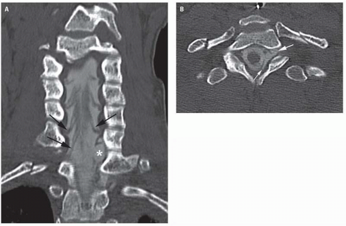
Figure 5.37. Normal uncinate processes (arrows) forming the joints of Luschka. A: Frontal radiograph. B: Lateral radiograph.
Figure 5.38. Degenerative changes along the Luschka joints. A: Frontal radiograph shows a relatively normal Luschka joint (open arrow). There are progressively severe changes of spondylosis at the other joints (1, 2, 3, 4). These changes include narrowing of the joint spaces, spur formation, and reactive sclerosis. B: Lateral radiograph shows the sclerotic margins of the uncinate processes (arrows) producing a lucency (Mach band) suggesting fractures. Horizontal Chance-type fractures do not occur in the cervical region.
Figure 5.39. Normal facet joints (arrows) overlap one another like shingles on a roof (imbrication). A: Lateral radiograph. B: Sagittal reconstructed CT image.
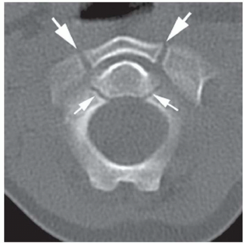
Each articular pillar has a superior and inferior articulating facet. The inferior and superior facets of contiguous vertebrae constitute an interfacetal (facetal or apophyseal) joint (Fig. 5.39). The inferior facet of the segment above anatomically lies above and posterior to the superior facet of the segment below. The plane of inclination of the interfacetal joints varies throughout the spine but the cervical spine is angled approximately 35 degrees caudally. The arrangement of these joints resembles the shingles on a roof, a term called imbrication. This appearance is identical on radiographs or on sagittal CT images. On axial CT and MR images, however, the interfacetal joints resemble a hamburger bun, with the flat portions articulating (Fig. 5.40). Facet dislocations and locking disturb this relationship and produce the “ reverse hamburger bunsign ” (Fig. 5.41). The laminae extend obliquely medially and posteriorly from the articular masses to fuse in the midline to form the spinolaminar line and spinous process. Together, the pedicles, articular pillars, and laminae form the posterior (neural) arch. The vertebrae are separated by the intervertebral disk.
Only gold members can continue reading. Log In or Register to continue