Chest: Trauma
John H. Harris Jr
Stuart E. Mirvis
GENERAL CONSIDERATIONS
For the purposes of this discussion, the chest shall include the thoracic cage and its soft tissues, portions of the shoulder girdles, the intrathoracic contents, and the diaphragm.
Whenever possible, the radiographic examination of the chest should be made with the patient erect because physiologic alterations of intrathoracic structures inherent in recumbency may simulate organic disease on the supine radiograph. However, in the practice of emergency radiology, it is required and expected that the physician interpreting emergency chest radiographs (CXRs) be solidly experienced in the evaluation of anteroposterior (AP) CXRs obtained in supine, semierect, and erect positions.
The technical factors employed in the production of a CXR are probably more critical than in the radiographic examination of any other body part. Pulmonary interstitial disease may be simulated by normal vascular and normal parenchymal markings made more prominent because of an underexposed CXR. Conversely, gross pulmonary or cardiovascular pathology may be obscured or obliterated by radiographic overexposure, poor radiograph-screen or patient-radiograph contact, or patient motion.
The radiographic examination of the chest may provide valuable information regarding the etiology or extent of acute intra-abdominal disease or trauma. Furthermore, intrathoracic abnormalities may produce symptoms referable to the upper abdomen. For these reasons, radiographic examination of the chest should always be considered in the evaluation of patients with acute symptoms that appear to arise within the abdomen.
The radiographic examinations of the chest of newborns, infants, and young children are inherently difficult to interpret. In these patients, strict adherence to established principles of positioning and radiographic technical factors is essential to accuracy of radiographic diagnosis.
The supine CXR can be expected to reflect the mediastinal hemorrhage and, when present, the left hemothorax, of exsanguinating acute traumatic aortic rupture (ATAR) in patients who survive this injury to reach the emergency center. On the contrary, conventional chest radiography does not display any direct signs of acute traumatic aortic tear (ATAT). However, the supine CXR, which is an essential component of the imaging assessment of the patient with blunt thoracic or thoracoabdominal trauma, coupled with a “coned-down” AP radiograph of the mediastinum using thoracic spine technique (“mediastinal” view, mediastinal radiograph [MXR]), very accurately demonstrates either a normal mediastinum (the absence of a mediastinal hematoma) in patients who therefore require no further consideration of acute traumatic aortic injury (ATAI) or signs consistent with a mediastinal hematoma in patients who therefore require additional imaging investigation for ATAT. In most institutions, multidetector computed tomographic aortography (MDCTA) is the initial examination for the detection of ATAT in the polytraumatized patient.
In some institutions, computed tomographic aortography (CTA) showing direct signs of ATAT is confirmed by catheter aortography. In most cases, CTA is the definitive study.
In some institutions, computed tomographic aortography (CTA) showing direct signs of ATAT is confirmed by catheter aortography. In most cases, CTA is the definitive study.
RADIOGRAPHIC EXAMINATION
The routine radiographic study of the adult chest consists of erect (standing) posteroanterior (PA) and lateral projections made in maximum inspiration (Fig. 13.1). Clinical situations occur in which it is impossible to obtain a standing erect PA radiograph of the chest. In these instances, and when possible, an erect sitting AP projection is preferable to a supine examination. However, in seriously ill or injured patients, the supine examination may be the only examination possible. One must therefore understand the physiologic changes that occur within the chest during recumbency and not interpret them as being abnormal.
Radiographs obtained in expiration may be misinterpreted as showing cardiomegaly and parenchymal densities at each base, suggesting atelectasis or developing pneumonitis (Fig. 13.2). As a general rule, if the posterior portion of the right ninth rib is visible above the diaphragmatic surface in the PA CXR in an adult, an adequate degree of inspiration may be assumed.
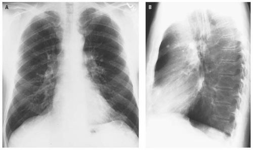 Figure 13.1. PA (A) and lateral (B) radiographs of a normal adult chest. |
Deep inspiration is particularly important in CXRs of infants and children (Fig. 13.3). This is because the poorly aerated lung produces a radiographic appearance that closely resembles pneumonia (Fig. 13.4).
In infants and children, it is preferable to attempt frontal (AP) and lateral radiographs in the erect position with the arms extended upward over the head and, when possible, the exposure timed to maximum inspiration. In these patients, maximum inspiration occurs in the quiet interval between crying—not when the patient is crying, which obviously represents expiration. If, for whatever reason, it is impossible to obtain erect frontal and lateral examinations of the chest of patients in this age group, perfectly adequate examinations can be obtained with the patient recumbent. However, again, it is essential that the arms be extended upward over the head and that the exposure be timed to maximum inspiration.
In the presence of major trauma, the radiographic examination of the chest is initially obtained in the supine position. Physiologically, the mediastinum is wider in this examination than in the erect chest examination, and the cardiac silhouette increases
in its transverse diameter. Although the superior mediastinum is wider, its margins remain distinct, and normal anatomic landmarks are identifiable (Fig. 13.5). Therefore, mediastinal widening alone in the supine examination of the chest does not constitute a radiographic sign of mediastinal hematoma, as is discussed subsequently.
in its transverse diameter. Although the superior mediastinum is wider, its margins remain distinct, and normal anatomic landmarks are identifiable (Fig. 13.5). Therefore, mediastinal widening alone in the supine examination of the chest does not constitute a radiographic sign of mediastinal hematoma, as is discussed subsequently.
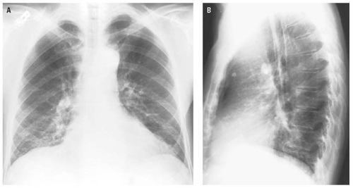 Figure 13.2. Effect of expiration on the chest radiograph of a normal adult subject. On the PA radiograph (A), expiration is characterized by increase in the transverse diameter of the cardiac silhouette and the superior medium, crowding of the interstitial markings and the basilar segmental arteries, and elevation of the diaphragm, all secondary to hypoventilation. Similar, although less obvious, changes occur on the lateral projection (B). |
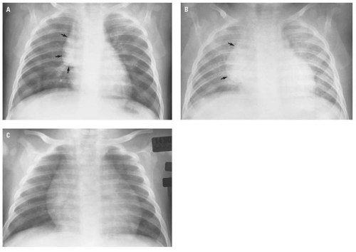 Figure 13.3. Effect of inspiration (A) and expiration (B) on the appearance of the frontal radiograph of a normal child’s chest. The sharply defined homogeneous soft tissue density in the right mediastinum (arrows) is the thymus. The normal frontal examination of a different child’s chest is seen in (C). |
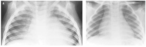 Figure 13.4. Crowding of parenchymal and vascular markings at the right base due to poor inspiration could be misinterpreted as pneumonia (A). These apparent parenchymal abnormalities have disappeared on the repeat CXR obtained with better inspiration (B). |
The supine CXR has serious diagnostic limitations that must be borne in mind when that examination is interpreted. Small or even moderate pleural effusions that layer out in the posterior pleural space in recumbency may not be easily discernible. Pneumothoraces may be impossible to detect in a supine radiograph because of air migration into the anterior pleural space. The pneumothorax suspected but not actually visible on a supine CXR may be confirmed by a lateral decubitus examination of the chest with the side of suspected pneumothorax up, by a horizontal beam supine lateral CXR, by computed tomography (CT), by an erect frontal CXR obtained during forced expiration (Fig. 13.6), or even by obtaining a frontal semierect CXR (Fig. 13.7). Some
of the views mentioned to assist in the diagnosis of pneumothorax obviously depend on the patient’s clinical condition and ability to assume, or be placed in, these positions. The frontal examination of the chest made in forced expiration is also very useful in the evaluation of possible nonopaque, endobronchial foreign bodies, as is subsequently illustrated in this chapter.
of the views mentioned to assist in the diagnosis of pneumothorax obviously depend on the patient’s clinical condition and ability to assume, or be placed in, these positions. The frontal examination of the chest made in forced expiration is also very useful in the evaluation of possible nonopaque, endobronchial foreign bodies, as is subsequently illustrated in this chapter.
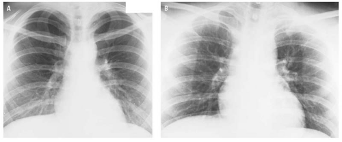 Figure 13.5. The effect of recumbency on the cardiovascular silhouette. Erect (A) and supine (B) radiographs of the chest of the same healthy subject. In recumbency (B), the superior mediastinal shadow and the transverse diameter of the heart increase in transverse dimension and the upperlobe pulmonary vessels increase in caliber. These changes are secondary to the physiologic redistribution of blood that occurs with recumbency. |
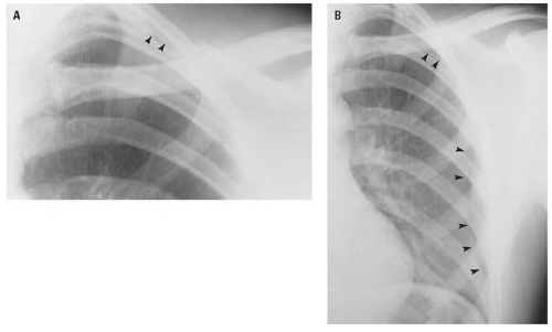 Figure 13.6. Effect of expiration on the detection of subtle pneumothorax. In the erect frontal examination of the chest made in deep inspiration (A), a very small, subtle apical pneumothorax (arrowheads) is barely perceptible. In the frontal examination of the chest made in forced expiration minutes later (B), the pneumothorax (arrowheads) is readily apparent. |
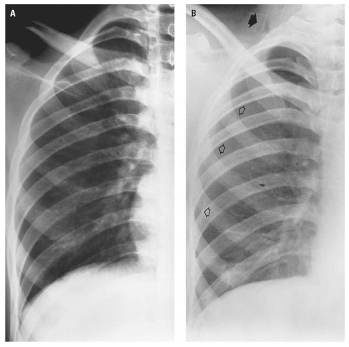 Figure 13.7. A: Supine chest radiograph of a patient stabbed in the right chest posteriorly. This examination is negative. B: Semierect chest radiograph taken shortly after A demonstrates both a pneumothorax (open arrows) and subcutaneous emphysema in the right side of the neck (closed arrow). |
The apical lordotic view (Fig. 13.8) provides maximum visualization of the apices of the lungs. This examination is, as its name implies, made with the patient in the lordotic position and is designed to project the anterior ends of the upper ribs and the clavicle away from the underlying apical pulmonary parenchyma.
Oblique views are useful to assess cardiac configuration, the hila, and the lateral costophrenic angles and to help localize subtle pulmonary abnormalities (Fig. 13.9).
As mentioned earlier, an erect PA radiograph of the chest should be an integral part of every “abdominal series” to establish that an intrathoracic process is not the etiology of upper quadrant abdominal symptoms and to ensure detection of pneumoperitoneum (Fig. 13.10). If the patient cannot assume the erect position, the left lateral decubitus radiograph of the abdomen should be obtained to evaluate for pneumoperitoneum.
With experience gained from the increasing use of CT since publication of the third edition of The Radiology of Emergency Medicine in 1993, and particularly with the advent of multidetector CT (MDCT), CT has become the major—and frequently the definitive—imaging modality relative to traumatic and nontraumatic conditions of the chest.1, 2, 3, 4, 5, 6, 7, 8, 9
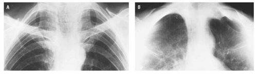 Figure 13.8. Apical lordotic view. In the erect frontal projection (A), the apex of each lung is largely obscured by superimposed densities of ribs, transverse processes, clavicles, calcified first costal cartilages, and the density of the sternocleidomastoid muscles. In the apical lordotic projection (B), the anterior chest wall structures have been projected free of the apices that are now clearly visible. |
In spite of the extensive experience with CTA and its 90% sensitivity, 98% specificity, and 90% positive predictive value,10 “thoracic aortography remains the standard of reference for the demonstration of acute traumatic aortic injury” (ATAI) according to Patel et al.11 However, MDCT is now accepted in many institutions as the definitive imaging procedure for patients suspected of having acute thoracic aortic dissection. CTA is readily available, examination time is short (measured in seconds), and the sensitivity and specificity of CTA for detecting aortic dissection is nearly 100%.12
Magnetic resonance imaging (MRI) and magnetic resonance angiography (MRA), because of the exquisite soft tissue detail and imaging in all planes, are particularly valuable in assessing the thoracic aorta for acute tear in young children and demonstration of acute traumatic diaphragmatic rupture. Limitations of the use of magnetic resonance (MR) in these acute conditions are the generic limitations of MR units(e.g., limited availability, length of scan time, and the intrinsic physical difficulty)to accommodate the extensive life-support systems required by severely traumatized patients.
With the exception of transesophageal echocardiography (TEE) in the detection of ATAT,13, 14 ultrasound has little application in the imaging evaluation of traumatic or nontraumatic emergent conditions of the chest. The principal disadvantage of TEE in the assessment of ATAT is its limited accessibility on a round-the-clock basis.
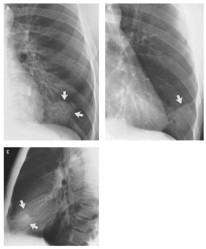 Figure 13.9. The location of the round pneumonia at the left base (arrows) on the PA CXR (A) is confirmed to be in the lingular segment of the left upper lobe by its position (arrows) on the left posterior oblique (B) and lateral (C) projections. |
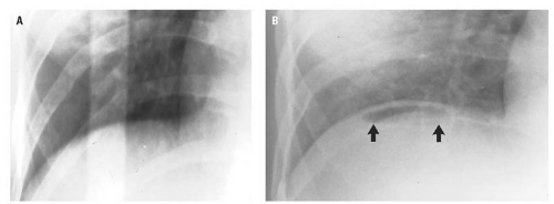 Figure 13.10. Supine examination of the abdomen (A) did not demonstrate the small pneumoperitoneum (arrows) seen beneath the right hemidiaphragm in the erect chest radiograph (B). |
RADIOGRAPHIC ANATOMY
The erect PA and lateral radiograph of the normal chest is seen in Figure 13.11. The intrathoracic portion of the trachea and carina are usually visible through the density of the mediastinal structures and the spine in the PA projection (Fig. 13.11A). The aortic arch and the descending thoracic aorta lie to the left of the midline. The descending aorta passes obliquely from above downward toward the diaphragm. The shadow of the descending aorta, with its black Mach edge, must not be confused with the mediastinal stripe (left paraspinal line), which has a white Mach edge, is parallel to the thoracic vertebral bodies, and represents the interface of paraspinal fat with the mediastinal pleura of the left lung. This anatomy is described and illustrated in greater detail later in this chapter in the discussion of traumatic injuries of the aorta.
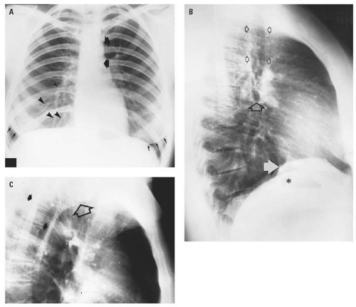 Figure 13.11. Normal adult chest radiograph. In the erect frontal projection (A), the aortic arch and descending thoracic aorta are indicated by the closed (solid) arrows. The curvilinear, tapering, branching soft tissue densities extending obliquely downward from the inferior portion of the right hilum represent right lower lobe segmental arteries (arrowheads). The curved, sharply defined soft tissue densities superimposed on each base and extending across the middle third of each hemidiaphragm (small stemmed arrows) represent breast shadows. In the full lateral projection (B), the small open arrows indicate the tracheal air column, and the large open arrow indicates the carina. The white arrow indicates the inferior vena cava, whereas the gastric air bubble is indicated by the asterisk. In the lateral radiograph of the chest (C), it is important to realize that the infraspinous portions of the scapulae (closed arrows) and the humeral head (open arrow) may be superimposed on the middle and posterior mediastinum and should be recognized as being normal structures. |
The hilar shadows are composed principally of the pulmonary arteries and veins, the walls of
the stem bronchi and their segmental divisions, lymph nodes, and areolar tissue. Calcification of hilar nodes is a frequent finding and is usually of no clinical significance. The “aortic-pulmonary mediastinal stripe” (Fig. 13.12) represents the mediastinal pleural reflection of the left upper lobe as it crosses the aortic arch and extends to the left hilum.15
the stem bronchi and their segmental divisions, lymph nodes, and areolar tissue. Calcification of hilar nodes is a frequent finding and is usually of no clinical significance. The “aortic-pulmonary mediastinal stripe” (Fig. 13.12) represents the mediastinal pleural reflection of the left upper lobe as it crosses the aortic arch and extends to the left hilum.15
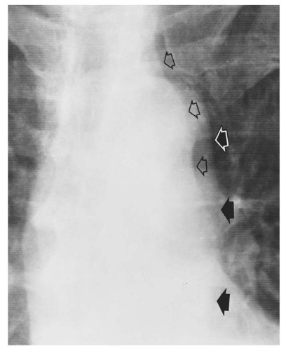 Figure 13.12. The “aorticopulmonary mediastinal stripe,” which represents the mediastinal pleural reflection of the left upper lobe as it crosses the aortic arch and extends to the left hilum, is indicated by the open arrows. The lateral margin of the descending thoracic aorta with its black Mach margin is indicated by the closed arrows. |
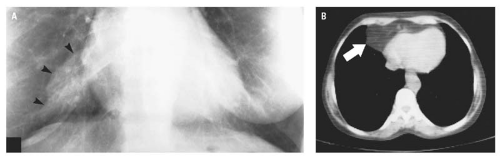 Figure 13.13. Cardiophrenic (pericardiac) fat pad. In the frontal radiograph of the chest (A), the rather sharply defined, irregularly rounded density through which pulmonary vascular structures are visible and which is located in the right cardiophrenic angle (arrowheads) has the characteristic radiographic findings of a pericardial fat pad. Axial CT (B) through the right cardiophrenic mass (arrow) demonstrates the low attenuation characteristic of fat, which is identical with that of the subcutaneous fat of the chest wall. |
The cardiophrenic angles are normally acute. A pericardial fat pad frequently occupies the right cardiophrenic angle. This normal structure may obscure the angle, but the cardiac and diaphragmatic margins are usually visible through it. The density of the fat pad is not as great and its margins are not as sharply defined as those of a pericardial cyst (Fig. 13.13).
The medial segment of the right middle lobe and the lingular segment of the left upper lobe wrap around the lateral heart borders. Consolidation of the entire middle lobe (Fig. 13.14) or its medial segment (Fig. 13.15) or of the lingular segment (Fig. 13.16) of the left upper lobe will obscure the contiguous arc of the heart border on the frontal radiograph. This phenomenon is referred to as the “silhouette” sign by Felson and Felson.16 A corollary of the silhouette sign is that a basilar consolidation that obscures or obliterates the diaphragmatic surface and through which the appropriate heart border is clearly visible represents lower lobe pneumonia (Fig. 13.17). The heart border remains visible because of the normal aerated lung-cardiac margin interface.
An important radiographic anatomic observation is that the apices of the upper lobes extend well above the level of the clavicles (Fig. 13.11).
The thin, sharply defined homogeneous soft tissue density located above and parallel to the superior cortex of the clavicles is called the
“companion shadow” (Fig. 13.11). This density represents the skin and subcutaneous fat covering the clavicle made visible by the air that fills the concavity of the supraclavicular fossa when the shoulders are rotated anteriorly for the PA CXR. Medially, the companion shadow is continuous with the lateral margin of the inferior portion of the sternocleidomastoid muscle. The companion shadow is effaced or obliterated when the supraclavicular fossa is filled with enlarged lymph nodes, which may not be clinically palpable.
“companion shadow” (Fig. 13.11). This density represents the skin and subcutaneous fat covering the clavicle made visible by the air that fills the concavity of the supraclavicular fossa when the shoulders are rotated anteriorly for the PA CXR. Medially, the companion shadow is continuous with the lateral margin of the inferior portion of the sternocleidomastoid muscle. The companion shadow is effaced or obliterated when the supraclavicular fossa is filled with enlarged lymph nodes, which may not be clinically palpable.
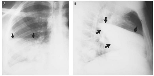 Figure 13.14. Consolidation of the entire right middle lobe (arrows) in frontal (A) and lateral (B) projections. In the frontal projection (A), the right heart border is completely obscured by the consolidation of the medial segment of the right middle lobe. The lateral arc of the right hemidiaphragm remains visible because the lateral segment of the middle lobe does not extend into the costophrenic angle. |
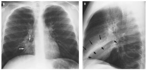 Figure 13.15. Inflammatory consolidation of the medial segment of the right middle lobe in frontal (A) and lateral (B) projections. In the frontal projection (A), the ill-defined area of increased density (arrows) obscures the right heart border. In the lateral projection (B), the area of consolidation is sharply defined inferiorly by the anterior portion of the major fissure (curved arrows). |
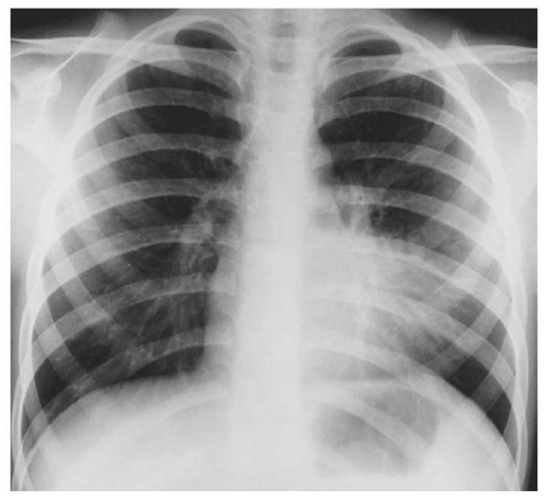 Figure 13.16. Obscuration of the left heart border by lingular segment pneumonia. Lingular segmental consolidation is an example of the “silhouette” sign. |
 Figure 13.17. Right lower lobe pneumonia represented by the ill-defined area of increased density that involves all the basilar segments with obliteration of the right hemidiaphragmatic surface. That the right heart border remains visible through this density reflects the normal right middle lobe-right heart border interface and confirms that the right basilar density is in the right lower lobe. |
The sternum is not well seen in the PA radiograph of the chest because it is almost completely obscured by the superimposed density of the mediastinal structures and the spine.
The lateral radiograph of the chest (Fig. 13.11B) dramatically illustrates the depth of the posterior costophrenic sulcus and the volume of the lower lobe that lies posterior to the dome of the diaphragm.
The posterior margin of the cardiac shadow is composed of the left atrium superiorly and the left ventricle inferiorly. The inferior vena cava (IVC) is commonly seen on the lateral radiograph of the chest as a posteriorly, sharply defined, homogeneous density extending upward through the diaphragm anterior to the posterior margin of the left ventricle (Fig. 13.18). Normally, at a distance 2.5 cm above the diaphragm, the posterior margin of the left ventricle should be less than 2.5 cm from the IVC.17 Conversely, an IVC-left ventricle distance greater than 2.5 cm indicates cardiomegaly with left ventricular preponderance. This assessment of cardiac size is thought to be more accurate than the cardiothoracic ratio.17
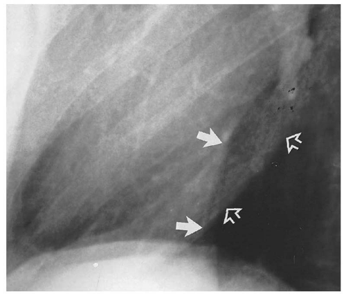 Figure 13.18. Normal relationship between the inferior vena cava (solid arrows) and the left ventricle (open arrows). |
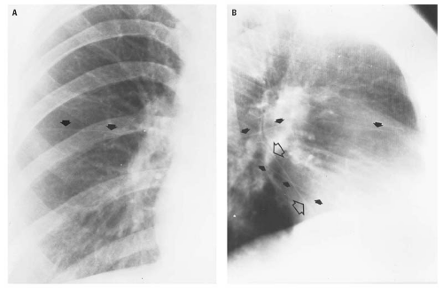 Figure 13.19. Interlobar fissures as seen in frontal (A) and lateral (B) projections. The right minor fissure (closed arrows) is seen in both projections. The inferior portion of the right major fissure (closed arrows) is obliquely vertically oriented in the lateral projection (B). In this projection, also, the inferior portion of the left interlobar fissure (open arrows) is visible. The inferior portions of the major fissures can be correctly identified by the fact that the right minor fissure crosses and extends posterior to the inferior portion of the left interlobar fissure (open arrows). |
The trachea is normally visible to the level of the carina (Fig. 13.11B).
The diaphragmatic surfaces can usually be lateralized on the lateral CXR by virtue of the air in the gastric fundus being related to the left hemidiaphragm (Fig. 13.11B).
When the patient’s arms are elevated for the lateral CXR (Fig. 13.11C), the scapulae rotate anterolaterally and their lateral margins become superimposed on the posterior third of the chest. Frequently, the glenoid fossa and the humeral head are projected on the superior mediastinum. These normal structures should not be considered as representing abnormal radiographic densities.
Interlobar fissures are frequently normally visible as thin linear or curvilinear densities (Fig. 13.19). The minor fissure of the right lung may be visible in frontal, lateral, or both projections. The major interlobar fissures are usually seen only in the lateral projection. Occasionally, the diaphragmatic portion of the major fissure may be oriented so as to be visible in the frontal CXR (Fig. 13.20).
The azygos fissure (Fig. 13.21), which defines the azygos lobe, is the result of invagination of both the visceral and parietal pleura by an anomalous course of the azygos vein over the apex of the right upper
lobe to its normal location at the junction of the trachea and the takeoff of the right stem bronchus. Because the azygos fissure results from the enfolding of both the visceral and the parietal pleura, it contains four layers of pleura. The location of the azygos fissure is variable in the medial aspect of the right upper lobe. The azygos fissure and lobe have no clinical significance but could conceivably be mistaken for the wall of a bleb or bulla.
lobe to its normal location at the junction of the trachea and the takeoff of the right stem bronchus. Because the azygos fissure results from the enfolding of both the visceral and the parietal pleura, it contains four layers of pleura. The location of the azygos fissure is variable in the medial aspect of the right upper lobe. The azygos fissure and lobe have no clinical significance but could conceivably be mistaken for the wall of a bleb or bulla.
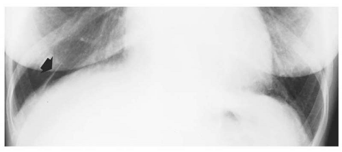 Figure 13.20. Inferior portion of the right major fissure (arrow) seen in frontal projection. |
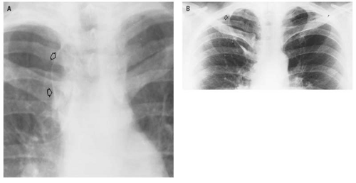 Figure 13.21. Configuration of the azygos lobe (open arrows) in two different patients (A and B). |
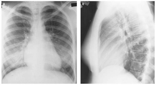 Figure 13.22. Vague, ill-defined, and poorly marginated densities at each base in the frontal projection (A) are caused by compression of the breast tissue. The lateral radiograph of the chest (B) is entirely normal. Specifically, there is no evidence of lower lobe pneumonia. The breast tissue accounted for the hazy densities at each base. |
The breast shadow itself may produce an ill-defined haziness at either base simulating an inflammatory process (Fig. 13.22). The difference
in density of the inferior portion of the lung fields following a radical mastectomy (Fig. 13.23) may be misleading if the observer is not aware of the absence of the breast shadow on the operated side.
in density of the inferior portion of the lung fields following a radical mastectomy (Fig. 13.23) may be misleading if the observer is not aware of the absence of the breast shadow on the operated side.
The routine examination of the ribs, when the patient’s condition will permit, must include an erect PA radiograph of the chest and each oblique projection of the affected side (Fig. 13.24). The indications for the erect frontal examination of the chest include, primarily, the detection of possible pneumothorax, pulmonary contusion, or pleural effusion and, secondarily, the recognition of preexisting or coexisting disease(i.e., left heart failure).
The purpose of examination of the affected hemithorax in each oblique projection is to visualize all segments of the ribs. Incomplete or minimally displaced rib fractures may be difficult or impossible to identify on the PA CXR alone and may frequently be recognized only in one of the oblique projections.
Portions of the lower ribs are obscured by the density of the upper abdominal contents and will not be visible using routine rib technique. When the clinical findings suggest an abnormality of the ribs below the diaphragm, an AP radiograph of the lower portion of the chest and upper abdomen using either abdominal or lumbar spine radiographic technique is required to evaluate the lower ribs as well as the lower thoracic and upper lumbar vertebrae.
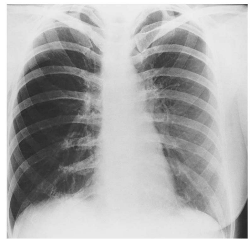 Figure 13.23. The apparent hyperlucency of the right lung is a manifestation of absent right anterior soft tissues subsequent to a right radical mastectomy. |
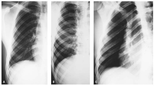 Figure 13.24. Routine radiographic examination for the ribs. This study must include erect CXR (A) and anterior (B) and posterior (C) oblique projections to demonstrate the full extent of each rib. The purpose of the erect frontal examination, in addition to visualizing the ribs, is to evaluate for pleural effusion, pneumothorax, or pulmonary contusion. |
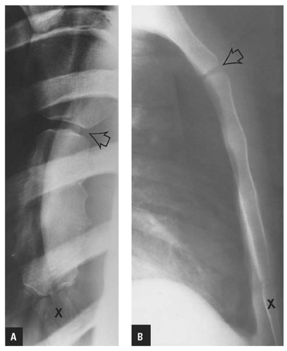 Figure 13.25. Routine radiographic examination of the sternum in frontal (A) and lateral (B) projections. The angle of Louis (open arrow) is clearly demonstrated in each projection. In this patient, the xiphoid (X) has not yet united. |
Standard texts on radiographic positioning describe the routine radiographic examination of the sternum to consist of frontal views made with the patient prone and rotated slightly off the midline in each direction and a lateral projection (Fig. 13.25). The frontal sternal views require positioning difficult for a patient with a suspected sternal injury and are extremely difficult to interpret. A properly positioned lateral radiograph of the sternum provides the best opportunity for detecting sternal fracture or dislocation. Prior to their fusion, the location and smoothly sclerotic margins of the sternal segments (Fig. 13.26) should distinguish these normal defects from fracture lines.
RADIOGRAPHIC MANIFESTATIONS OF TRAUMA
Trauma to the chest usually involves multiple organ systems and different anatomic regions (e.g., the chest wall including the thoracic cage, the pleural space, and lungs; the extrapleural space and mediastinum; the heart and great vessels; and the spine and shoulders). To facilitate the discussion of the effects of trauma to the chest, an arbitrary decision has
been made to discuss the effects of trauma on each of the components of the chest separately. Although it is certainly possible that individual components of the chest may be injured separately (e.g., isolated rib fracture[s] or pulmonary contusion without rib fractures), far more commonly multiple organ systems or anatomic regions are involved simultaneously. Despite the arbitrary organization of this chapter, the reader is reminded that, particularly in the severely or multiply traumatized patient, radiographic signs of multiple organ involvement will be the rule rather than the exception. That intellectual approach to the CXR of the massively injured patient should prompt an orderly and systematic approach to its interpretation.
been made to discuss the effects of trauma on each of the components of the chest separately. Although it is certainly possible that individual components of the chest may be injured separately (e.g., isolated rib fracture[s] or pulmonary contusion without rib fractures), far more commonly multiple organ systems or anatomic regions are involved simultaneously. Despite the arbitrary organization of this chapter, the reader is reminded that, particularly in the severely or multiply traumatized patient, radiographic signs of multiple organ involvement will be the rule rather than the exception. That intellectual approach to the CXR of the massively injured patient should prompt an orderly and systematic approach to its interpretation.
 Figure 13.26. Normal appearance of the sternum in an adolescent. The angle of Louis is indicated by the open arrow. The body segments (closed arrows) are physiologically incompletely fused. |
Radiography is usually not needed to establish the presence of soft tissue trauma of the chest wall. Subcutaneous emphysema, which may be the most obvious sign of a subtle pneumothorax, can be detected only on the AP CXR (Fig. 13.27).
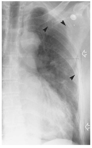 Figure 13.27. The small amount of subcutaneous emphysema along the left lateral chest wall (open arrows) in this patient with multiple minimally displaced rib fractures (arrowheads), but with no left chest laceration, should alert the observer that a pneumothorax must be present. |
Skeletal Injuries
The manubrium and body of the sternum are united by cartilage at the sternal synchondrosis (the angle of Louis). Blunt trauma to the anterior chest wall can result in dislocation at this site (Fig. 13.28).
Fracture of the sternum usually occurs in its body (Fig. 13.29) but may also involve the manubrium (Fig. 13.30). Clinically, the significance of sternal fracture lies in the mortality rate of 25% to 45%,18 which results not from the fracture per se but from associated injuries within the chest, such as cardiac injury, ATAI, or tracheobronchial injury. Gibson and colleagues19 reported a 75% incidence of head trauma associated with sternal fractures caused by motor vehicle accidents. Therefore, the clinician must maintain a high index of suspicion regarding the high association of sternal fractures and head trauma so that a sternal fracture, when present, may serve to alert the clinician to possible associated serious intrathoracic injury. The essential radiograph required to establish the diagnosis of sternal injury is the lateral projection, which may easily be obtained with the horizontal beam with the patient recumbent.
The anterior chest wall hematoma associated with sternal dislocation or fracture may produce the appearance of an ill-defined widening of the mediastinum (Fig. 13.29A) on the supine CXR similar to the appearance of the mediastinal hematoma associated with, but not caused by, ATAT. Some very salient observations regarding the relationship between mediastinal width and ATAT must be stated at this point, although these are amplified in greater depth subsequently in this chapter during the discussion of ATAI. In the first place, and contrary to much surgical and radiologic literature, a mediastinal width greater than 8.0 cm, with or without irregular margins, may be simply the normal appearance of the mediastinum due to recumbency. Second, although it has been established that an indirect relationship does exist between the presence of a mediastinal hematoma and acute aortic tear,20, 21, 22, 23 the hematoma is evidenced on the plain CXR by specific signs rather than simply “superior mediastinal widening.” The radiographic signs of mediastinal hematoma are described and illustrated in considerable detail later in this chapter in the discussion of ATAI. The CXR illustrated in Figure 13.39A is insufficiently penetrated for
adequate evaluation of the presence of a mediastinal hematoma. It would be a major diagnostic error, if not an actual injustice, to suggest aortography based on the CXR illustrated in Figure 13.29A. Finally, there is no established relationship between sternal injury and aortic injury.
adequate evaluation of the presence of a mediastinal hematoma. It would be a major diagnostic error, if not an actual injustice, to suggest aortography based on the CXR illustrated in Figure 13.29A. Finally, there is no established relationship between sternal injury and aortic injury.
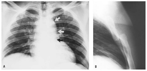 Figure 13.28. In the erect frontal examination of the chest (A) of this patient who received blunt trauma to the anterior chest wall in a motor vehicle accident, the superior mediastinum appears widened. However, the aortic arch and the descending thoracic aorta (arrows) remain visible. These structures are usually obscured or obliterated by a mediastinal hematoma. The lateral radiograph of the chest (B) demonstrates a complete posterior dislocation of the manubrium with respect to the body of the sternum. The superior mediastinal widening seen in the frontal projection (A) is caused by the anterior chest wall soft tissue swelling associated with the dislocation. |
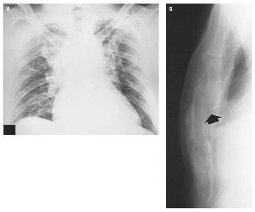 Figure 13.29. The frontal examination of the chest (A) of this patient involved in a motor vehicle accident demonstrates ill-defined mediastinal widening. In this instance, however, the apparent superior mediastinal widening was caused by anterior chest wall soft tissue hematoma secondary to the sternal body fracture (arrow, B). The frontal examination of the chest (B) is not sufficiently radiographically penetrated to evaluate the mediastinal structures for the presence of a mediastinal hematoma. |
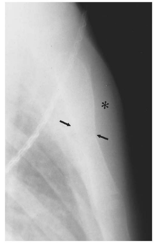 Figure 13.30. Fracture of the manubrium (arrows) with accompanying presternal hematoma (asterisk). |
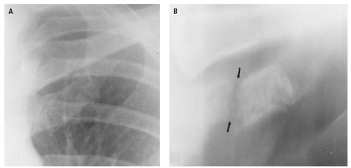 Figure 13.31 The fracture of the calcified left first costal cartilage that is not visible in the frontal projection (A) is clearly evident on the frontal tomogram (B, arrows). |
Rib fractures are usually the result of either compression of the chest or a direct blow to the chest wall. The former type of injury, resulting in a decrease in the arc of the ribs, causes an outward break at the site of greatest compression. This “spring fracture” is rarely associated with puncture of the lung. Direct localized trauma to the chest wall, when of sufficient force, results in fracture at the site of impact. In this circumstance, the fracture ends are more likely to penetrate the chest wall, producing a hemothorax or pneumothorax.
Blunt trauma to the chest may produce incomplete, nondisplaced rib fractures that may not be discernible on the initial CXR. If rib fracture is suspected clinically, or if pain persists, radiographs of the ribs obtained in 10 to 14 days will usually demonstrate callus formation at the fracture site, thereby establishing the diagnosis. Except for a densely calcified first costal cartilage (Fig. 13.31), costal cartilage fractures and costochondral separation are not radiographically visible.
Minimally displaced rib fractures or fractures occurring in the arc of the ribs between the anterior and posterior axillary lines are commonly demonstrated only in oblique projections (Figs. 13.32 and 13.33). On the frontal CXR, minimally displaced rib fractures may be heralded by a focal extrapleural hematoma (Figs. 13.33 and 13.34) or small pneumothorax (Fig. 13.35).
Rib fractures are uncommon in children because of the resiliency of the thoracic cage. However,
with a history of appropriate trauma, the possibility of a rib fracture in a child or any of its possible complications (e.g., pulmonary contusion, pneumothorax, or pleural effusion) must be actively considered during assessment of the radiograph (Fig. 13.36). Similarly, blunt thoracoabdominal trauma to a child may cause pulmonary and/or intraperitoneal injury without causing a rib fracture (Fig. 13.37).
with a history of appropriate trauma, the possibility of a rib fracture in a child or any of its possible complications (e.g., pulmonary contusion, pneumothorax, or pleural effusion) must be actively considered during assessment of the radiograph (Fig. 13.36). Similarly, blunt thoracoabdominal trauma to a child may cause pulmonary and/or intraperitoneal injury without causing a rib fracture (Fig. 13.37).
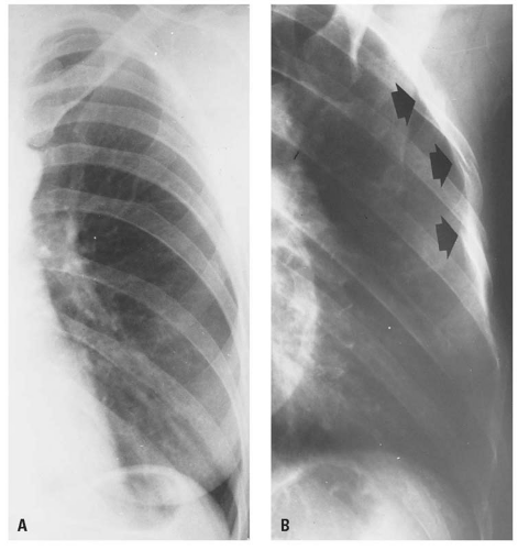 Figure 13.32. Minimally displaced, acute, complete fractures in the anterior axillary line of the left upper ribs are not visible in the frontal chest radiograph (A) but are clearly evident in the left posterior oblique projection (B, arrows). |
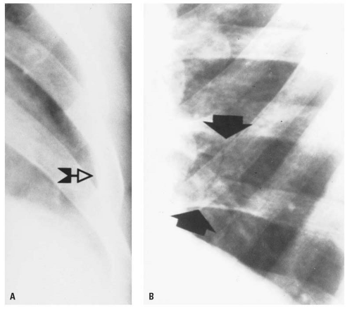 Figure 13.33. In the frontal projection (A), the localized extrapleural hematoma (stemmed arrow) marks the site of a rib fracture that is only radiographically visible in the left anterior oblique projection (B, arrows). |
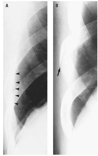 Figure 13.34. The small extrapleural hematoma (arrowheads) along the right lateral chest wall is the only sign in the frontal chest radiograph (A) suggestive of the rib fracture (arrow) demonstrated in the right anterior oblique projection (B). |
Fractures of the upper ribs are uncommon because the upper ribs are protected by the clavicle, scapula, and large muscle masses of the anterior and posterior chest walls. When present, either alone or in conjunction with fracture of the bones of the shoulder girdle, these fractures indicate simply an injury of considerable force. Contrary to an opinion frequently cited in surgical and radiographic literature, upper (thoracic inlet) rib fractures are not associated with an increased incidence of aortic injury. In fact, Fisher and colleagues,24 in a study of approximately 200 patients, clearly demonstrated that there is no statistically significant difference in the frequency of acute aortic brachiocephalic arterial injury between patients with or without thoracic inlet rib fractures. Lee and colleagues,25 in a comparative analysis of 62 patients with ATAT and 486 without ATAT, found that although fracture of the rib(s) was the most common thoracic skeletal injury associated with ATAT, “the positive predictive value of rib fractures in evaluating ATAT was only 14.7%, a rate similar to the incidence of ATAT at most trauma centers,” and therefore of no value in determining who should have CTA or traditional aortography.
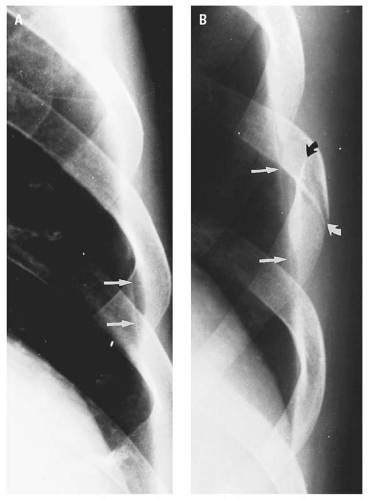 Figure 13.35. The small, focal pneumothorax (arrows) is the only radiographic sign in the frontal chest radiograph (A) of the complete fracture (curved arrows) demonstrated in the left anterior oblique projection (B). |
However, because of the magnitude of the causative force, upper rib fractures are commonly associated with pneumothorax or hemothorax, subcutaneous emphysema, pulmonary contusion, and
scapular fractures. All these associated injuries, in addition to the complex normal skeletal anatomy of the thoracic inlet, make the recognition of inlet rib fractures radiographically difficult (Fig. 13.38).
scapular fractures. All these associated injuries, in addition to the complex normal skeletal anatomy of the thoracic inlet, make the recognition of inlet rib fractures radiographically difficult (Fig. 13.38).
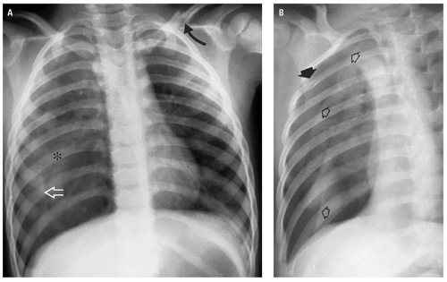 Figure 13.36. This 4-year-old child sustained blunt trauma to the chest. In addition to the displaced fracture in the middle third of the left clavicle (curved arrow), the erect PA radiograph of the chest (A) revealed right pulmonary contusion (asterisk) and a right pneumothorax (open arrow). The pneumothorax (open arrows) is seen to best advantage in the oblique radiograph (B). The only thoracic cage abnormality was a complete, minimally displaced fracture of the midaxillary line of the right third rib (closed arrow). |
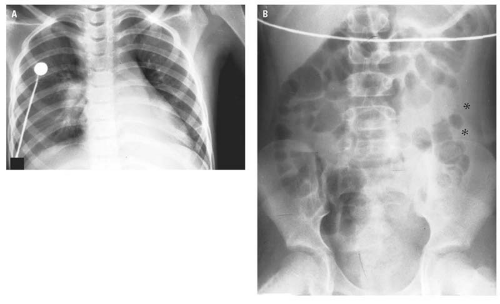 Figure 13.37. Blunt left thoracoabdominal trauma in a child without rib fracture. The AP chest radiograph (A) reveals atelectasis of the left lower lobe. In the supine radiograph of the abdomen (B), the soft tissue density (asterisks) displacing the descending colon from the left flank stripe represents blood in the left paracolic gutter from a ruptured spleen. The signs of hemoperitoneum require more definitive examination by orally and intravenously enhanced abdominal CT. |
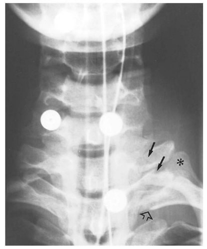 Figure 13.38. Fractures of the left first and second transverse processes (stemmed arrows), dislocation of the left first rib (asterisk), and fracture of the neck of the left second rib (open arrow) are all difficult to detect because of the superimposition of the skeletal parts at the thoracic inlet. |
The lower ribs, being less securely attached anteriorly, are more mobile and less susceptible to fracture by blunt trauma. However, these ribs may be fractured by a forceful direct blow and, when such a fracture occurs on the left, splenic and/or renal injury should be automatically considered, and lower rib fractures on the right should prompt an automatic consideration of hepatic and/or renal injury.
Flail chest is defined as segmental fractures of three or more consecutive ribs. Segmental fracture refers to two fracture sites in the same rib, resulting in a separate fragment that is free floating. It is taught that flail chest is clinically diagnosed by recognition of paradoxical movement of the flail segment during respiration due to chest pain. The clinical difficulty with this concept is that the paradoxical movement is very difficult to observe even under optimum conditions and particularly in patients with shallow respirations, in heavily muscled or obese patients, or in women with large breasts. Consequently, the primary responsibility for identification of a flail chest rests with the radiologist. That responsibility is not easily discharged because the diagnosis must almost invariably be made from a single supine CXR. Usually, the patient’s condition precludes obtaining oblique radiographs of the ribs. Additionally, because of the chest trauma, the examination will have been obtained in relative hypoventilation. Pulmonary contusion, pneumothorax, pleural effusion, and subcutaneous emphysema, commonly present, further obscure rib delineation. Therefore, in patients with major blunt thoracic or thoracoabdominal trauma, the presence of multiple rib fractures must prompt a diligent search for segmental rib fractures. Recognition of flail chest is of clinical significance because of its effect on pulmonary physiology, which is usually also adversely affected by pulmonary contusion or hemopneumothorax. Figures 13.39, 13.40 and 13.41
illustrate the difficulty in identifying the segmental fractures of flail chest as well as the evidence of the magnitude and diffusion of the force required to produce flail chest, such as the number of ribs fractured, pulmonary contusion, and the frequently associated clavicular and scapular fractures.
illustrate the difficulty in identifying the segmental fractures of flail chest as well as the evidence of the magnitude and diffusion of the force required to produce flail chest, such as the number of ribs fractured, pulmonary contusion, and the frequently associated clavicular and scapular fractures.
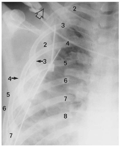 Figure 13.39. Right flail chest involving ribs 2 through 7. The posterior fracture sites are fairly readily apparent; those in the middle and anterior axillary lines are difficult to discern because they are only minimally displaced and are obscured by the density of the pleural effusion, pulmonary contusion, and the chest wall soft tissues. A comminuted, displaced fracture is present in the middle third of the right clavicle (open arrow). |
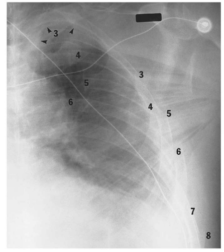 Figure 13.40. Left flail chest in which the lateral chest wall fracture sites are much more apparent than the posterior fracture sites in ribs 3 through 6. An apical pneumothorax (arrowheads) is barely perceptible. The oblique linear lucencies represent subcutaneous emphysema within the pectoral muscles. |
Harris and Harris26 reported that scapular fractures were missed on the initial emergency center CXR in 43% of 100 patients with major blunt thoracic trauma. In 72% of the missed scapular fractures, the scapular fracture was visible on the initial supine CXR but may have been obscured by rib or clavicular fractures, pulmonary contusion, pleural effusion, subcutaneous emphysema, radiograph identification labels, or monitoring leads. Before 1984, when Hardegger and colleagues27 advocated open reduction and internal fixation of fractures of the glenoid fossa or scapular neck as the preferred treatment for these injuries, the failure to diagnose a scapular fracture did not significantly adversely affect patient care. Because it is customary to treat all the orthopedic injuries requiring surgical management at the same time and because open reduction and internal fixation is now the treatment of choice for displaced glenoid fossa and neck fractures, it is very important that scapular fractures be identified on the initial emergency center CXR. Consequently, instead of clavicular and upper rib fractures, pulmonary contusion, and subcutaneous emphysema being offered as excuses for not recognizing scapular fractures, these same injuries should be considered as indicators for a diligent search for scapular fractures.
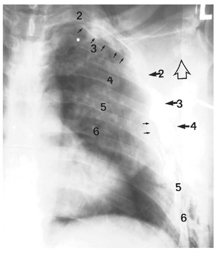 Figure 13.41. Subtle left flail chest involving ribs 2 through 6. A marginal pneumothorax (small stemmed arrows) is difficult to visualize but is imperative to identify. A fracture of the neck of the scapula is indicated by the open arrow, and subcutaneous emphysema is present along the left lateral chest wall and in the left supraclavicular fossa. |
Lee and colleagues28 reported that although three or more rib fractures in patients 14 years or older carried an increased risk of splenic or hepatic injury, there was no association between the number of rib fractures and aortic injury.
Sternoclavicular dislocation is a rare injury, accounting for less than 1% of all types of dislocations.29 The dislocation is usually posterior and may be caused by indirect trauma applied to the posterolateral aspect of the shoulder by a force that drives the lateral end of the clavicle anteriorly. The
taut costoclavicular ligament, acting as a fulcrum, causes the medial end of the clavicle to be levered posteriorly.30 In our experience, however, the more common mechanism of injury is massive direct trauma to the anterior chest wall, driving the medial end of the clavicle posteriorly or posterolaterally (Fig. 13.42). Posterior dislocation at the left sternoclavicular joint is particularly clinically important because of the proximity of the left subclavian vein. Clinically, patients with sternoclavicular dislocation have a large hematoma and ecchymosis of the upper anterior chest wall and asymmetry of the clavicles to palpation. Radiographically, the dislocation is difficult to diagnose on the AP CXR because displacement is usually minimal (Figs. 13.43 and 13.44), because the normal sternoclavicular anatomy may appear altered simply by rotation of the chest (Fig. 13.43A), and because of superimposed skeletal structures (Fig. 13.44). The dislocation is usually recognizable in a straight supine CXR by lateral displacement of the proximal end of the clavicle (Fig. 13.45) or by asymmetry of the proximal ends of the clavicle (Fig. 13.43A). The quickest and most accurate method to examine the sternoclavicular joint is by CT (Figs. 13.43B and 13.45B).
taut costoclavicular ligament, acting as a fulcrum, causes the medial end of the clavicle to be levered posteriorly.30 In our experience, however, the more common mechanism of injury is massive direct trauma to the anterior chest wall, driving the medial end of the clavicle posteriorly or posterolaterally (Fig. 13.42). Posterior dislocation at the left sternoclavicular joint is particularly clinically important because of the proximity of the left subclavian vein. Clinically, patients with sternoclavicular dislocation have a large hematoma and ecchymosis of the upper anterior chest wall and asymmetry of the clavicles to palpation. Radiographically, the dislocation is difficult to diagnose on the AP CXR because displacement is usually minimal (Figs. 13.43 and 13.44), because the normal sternoclavicular anatomy may appear altered simply by rotation of the chest (Fig. 13.43A), and because of superimposed skeletal structures (Fig. 13.44). The dislocation is usually recognizable in a straight supine CXR by lateral displacement of the proximal end of the clavicle (Fig. 13.45) or by asymmetry of the proximal ends of the clavicle (Fig. 13.43A). The quickest and most accurate method to examine the sternoclavicular joint is by CT (Figs. 13.43B and 13.45B).
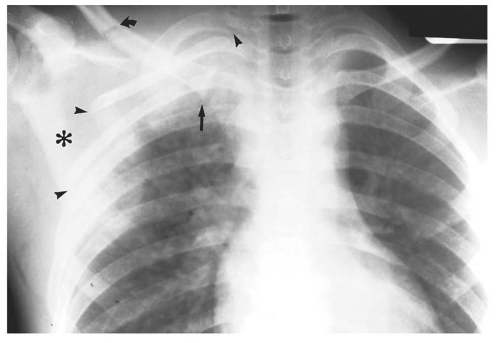 Figure 13.42. Massive direct right upper anterior chest wall trauma resulted in dislocation of the right sternoclavicular joint (straight arrow); fractures of the right first, second, and third ribs (arrowheads); a fracture in the middle third of the clavicle (curved arrow); and a large right axillary hematoma (asterisk). |
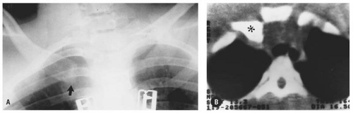 Figure 13.43. Right sternoclavicular dislocation. In the frontal projection of the thoracic inlet (A), the distal end of the right clavicle (arrow) is inferiorly displaced with respect to the left. The axial CT image (B) demonstrates the proximal end of the right clavicle (asterisk) to be posteriorly dislocated with respect to the manubrium. |
Pulmonary Contusion
Blunt chest trauma may cause pulmonary laceration, hematoma, and/or contusion. Of these, pulmonary contusion is the most common, reported to occur in 30% to 75% of blunt chest trauma patients.31 In a review of 144 consecutive patients with pulmonary contusion and/or flail chest, isolated flail chest and pulmonary contusion each had a mortality rate of 16%. In combination, the mortality rate increased to 42%.32 Pulmonary contusion may occur without rib fractures,31, 33, 34 particularly in children in whom the chest wall is more compliant than in adults.35
Pulmonary contusion is the result of compressive force to the lung parenchyma at the time of impact and of a negative force applied to the lung during recoil after the causative force is dissipated.
Both of these forces result in alveolar and interstitial hemorrhage and edema.35, 36, 37 The contusion may be focal and mild (Fig. 13.46) or extensive and severe (Fig. 13.47). Pulmonary contusion is usually mild, usually clears without producing significant respiratory disturbance, and may be clinically masked by other conditions such as flail chest, pneumothorax, or hemothorax. Even when severe, the extent and significance of the lesion, which may not initially be appreciated either clinically or radiographically, is recognized only by arterial PO2 levels reflecting hypoxia. Therefore, early in the post blunt chest trauma state, alteration of arterial blood gas values is the most sensitive indicator of the presence of pulmonary contusion.
Both of these forces result in alveolar and interstitial hemorrhage and edema.35, 36, 37 The contusion may be focal and mild (Fig. 13.46) or extensive and severe (Fig. 13.47). Pulmonary contusion is usually mild, usually clears without producing significant respiratory disturbance, and may be clinically masked by other conditions such as flail chest, pneumothorax, or hemothorax. Even when severe, the extent and significance of the lesion, which may not initially be appreciated either clinically or radiographically, is recognized only by arterial PO2 levels reflecting hypoxia. Therefore, early in the post blunt chest trauma state, alteration of arterial blood gas values is the most sensitive indicator of the presence of pulmonary contusion.
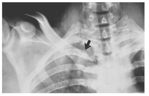 Figure 13.44. Minimally displaced right sternoclavicular dislocation. The medial end of the right clavicle (arrow) is both laterally and slightly caudally dislocated. The position of the clavicle is obscured by multiple rib fractures, hydropneumothorax, and pulmonary contusion, all indicating massive direct chest trauma. |
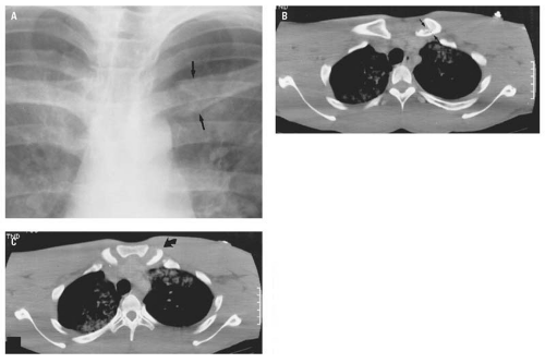 Figure 13.45. Left sternoclavicular fracture-dislocation. In the frontal projection of the chest (A), the medial end of the left clavicle (arrows) is laterally and slightly caudally displaced, and its inferomedial corner is not well delineated. The axial CT images (B and C) demonstrate posterior dislocation (curved arrow) and fracture (arrows) of the medial end of the left clavicle. |
Pathophysiologically, the blast effect of blunt chest trauma, which compresses the lung tissue, results in parenchymal hemorrhage and edema. When the initiating force is released, the lung rebounds, producing an abrupt negative pressure on the already damaged lung tissue. The hemorrhage occurs at the alveolar-capillary level, resulting in both intra-alveolar and interstitial extravasation of blood and edema. The ensuing cellular response to tissue damage combines with the hemorrhage and edema to produce a progressive O2 diffusion barrier and hypoxemia, which may initially be paradoxical with respect to the clinical and radiographic appearance of the patient and which may become progressively more severe.
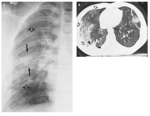 Figure 13.46. Mild pulmonary contusion limited to the right midlung zone (open arrows, A). Only in the center of the contusion is a smaller discrete area of focal consolidation (arrows), which could represent an area of more severe contusion or a hematoma. The peripheral location of the pulmonary contusion is shown by CT (open arrows, B). CT also shows that the area of increased density thought to be a focal hematoma on the PA CXR is actually a focal area of atelectasis (arrowheads) posterior to the contusion. CT also shows a focal contusion of the left lung (curved arrows) not recorded on the CXR. |
The natural history of uncomplicated pulmonary contusion is a dynamic process, with the area of contusion becoming progressively more extensive during the initial 24 hours, followed by a gradual clearing during the 48 to 72 hours after injury. This sequence is reflected radiographically in Figures 13.48 and 13.49. Consequently, the radiographic appearance of pulmonary contusion will vary not only with the magnitude of the causative force but also with the length of time between injury and the initial CXR. Because today’s efficient patient transport systems frequently deliver the traumatized patient to the emergency center within an hour of the time of injury, the initial CXR may be negative for signs of pulmonary contusion. Conversely, the CXR of a patient seen initially several hours following blunt chest trauma will demonstrate well-established changes of pulmonary contusion (Fig. 13.50).
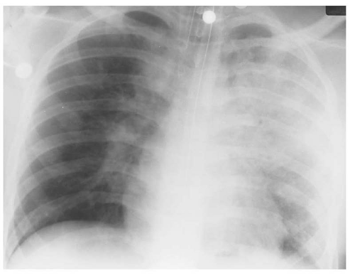 Figure 13.47. Extensive, severe pulmonary contusion involving the area of the majority of the left upper lobe and the atypical segment of the left lower lobe. |
The radiographic signs of pulmonary contusion may not be present immediately but are visible in 70% of cases within 1 or 2 hours after injury.31 In the remaining 30%, radiographic evidence of pulmonary contusion may not appear until 6 to 24 hours after injury.31, 34 For this reason, serial radiographs of the chest are indicated in patients whose initial chest examinations do not demonstrate changes of pulmonary contusion following significant blunt chest trauma.
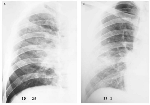 Figure 13.48. Pulmonary contusion. The initial chest radiograph (A) obtained approximately 3 hours postinjury demonstrates an extensive, ill-defined patchy parenchymal density that represents contusion of the right upper and middle lobes. The contusion had almost completely cleared on the frontal examination obtained approximately 72 hours postinjury (B). |
In patients with massive blunt chest trauma, the radiographic signs of pulmonary contusion will be positive on the initial supine chest radiograph (Fig. 13.39). The characteristic radiographic appearance of pulmonary contusion consists of patchy, illdefined areas of parenchymal density that may be either solitary and localized (Fig. 13.49), multiple, or diffuse (Fig. 13.51). Multiple foci of contusion in adjacent portions of the lung may coalesce. The area of contusion does not respect anatomic divisions of the lung, and therefore, the changes of pulmonary contusion on CXRs do not coincide with any of the anatomic divisions of the lung.
MDCT accurately reflects the pathophysiology of pulmonary contusion (Fig. 13.46B). On CT, the pulmonary contusion is peripheral and commonly contiguous with the adjacent pleura, involves adjacent segments and/or lobes of the lung without regard for segmental or lobar anatomic divisions, is variable in its degree of involvement, and shows signs of both airway and parenchymal involvement.
Complications of pulmonary contusion include pneumonia, pulmonary hemorrhage (hematoma), and traumatic pulmonary pseudocyst formation. Pneumonia is usually a relatively late complication and is associated with the usual clinical signs of pulmonary infection. Radiographically, postcontusion pneumonia resembles any other bacterial pneumonia except that in this instance, there is a direct radiographic continuum from the initial contusion to the subsequent area of inflammatory consolidation.
Pulmonary hematoma is a collection of blood in an area of pulmonary laceration. The hematoma is probably not a complication of the contusion per se but more likely was present at the time of initial chest trauma but was marked by the more extensive contusion and only became radiographically visible as the contusion cleared (Fig. 13.49). Pulmonary hematoma is usually described as a flame-shaped area (Figs. 13.49 and 13.52) of increased density that persists after the surrounding
contusion clears. The hematoma may be visible on the initial CXR and distinguished from the surrounding contusion as a sharply defined area of homogeneous density within the contusion (Fig. 13.53).
contusion clears. The hematoma may be visible on the initial CXR and distinguished from the surrounding contusion as a sharply defined area of homogeneous density within the contusion (Fig. 13.53).
 Figure 13.49. Pulmonary contusion complicated by pulmonary laceration and hemorrhage. The ill-defined patchy density in the left upper lobe on the initial chest radiograph (A) obtained shortly after the patient sustained blunt left upper chest trauma represents a pulmonary contusion. Twelve hours later (B), the area of contusion had increased in size radiographically. By 36 hours postinjury (C), the contusion had partially resolved, but within the area of contusion, a smaller, more discrete density is visible that represents the pulmonary hemorrhage, which persisted after the radiographic signs of contusion had completely cleared (D) 5 days postinjury. |
 Figure 13.50. Well-established pulmonary contusion involving the majority of the left upper lobe and the apical segment of the left lower lobe subsequent to direct blunt trauma to the left hemithorax. |
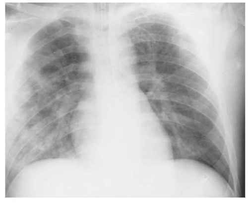 Figure 13.51. The mottled areas of increased density that are irregularly distributed throughout the entire right lung, that are more dense peripherally than centrally, and that show areas of consolidation are typical of the radiographic appearance of pulmonary contusion. |
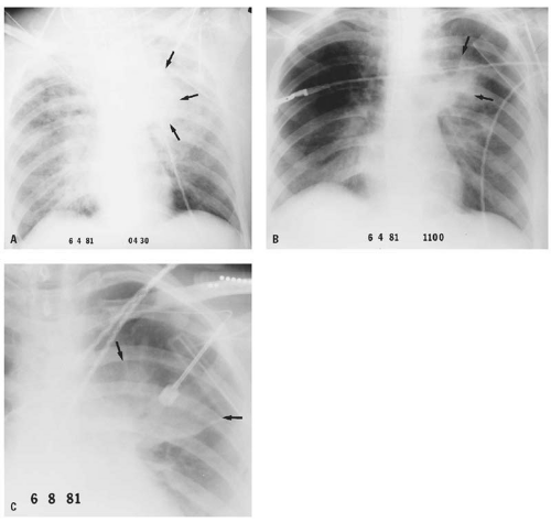 Figure 13.52. Concomitant left upper lobe pulmonary contusion and pulmonary hematoma in a patient who sustained massive blunt chest trauma. The initial chest radiograph (A) demonstrates changes of fluid overload. In addition, the extensive area of increased density in the left upper and middle lung fields, with a central homogeneous consolidation (arrows), was thought to represent pulmonary contusion with probable pulmonary hematoma. Within 7 hours (B), the signs of fluid overload had cleared, and the left pulmonary contusion had significantly improved, leaving the central flame-shaped area of consolidation (arrows) consistent with pulmonary hematoma. Four days posttrauma (C), the contusion had cleared, but the pulmonary hematoma (arrows) persisted. |
The final complication of pulmonary contusion is the development of single or multiple thin-walled, air-filled spaces within the area of pulmonary contusion referred to as posttraumatic pneumatocele (Fig. 13.54).38, 39 Ellis40 referred to these lesions as “cysts.” Santos and Mahendra41 recommend the term “traumatic pulmonary pseudocyst” because the pathologic definition of a cyst requires an epithelial lining, which these evanescent lesions do not have, and because the term pneumatocele has historically been associated with pneumonia. The important aspects of traumatic pseudocysts are that although they usually occur 4 to 5 days after closed chest trauma,42 they may rarely be present on the initial CXR. They resolve spontaneously, do not require extensive workup, and do not require surgical intervention.41
As a reminder that the chest and abdomen must be considered as a single entity in the presence of blunt thoracic or thoracoabdominal trauma, basilar
pulmonary contusion may be the most obvious radiographic finding in patients with lower rib fractures and intra-abdominal injury (Fig. 13.55). It must be apparent that pulmonary contusion may occur without rib fractures in both children (Fig. 13.50) and adults (Fig. 13.56). Finally, pulmonary contusion may resemble aspiration pneumonia in its radiographic appearance. However, the distinction may reasonably be made on the basis that aspiration pneumonia is usually more central, is of greater density medially than peripherally, and is limited to bronchial distribution(e.g., subsegmental or segmental). Pulmonary contusion, on the other hand, is usually more peripheral within the lung, is more dense laterally than medially, and does not respect the segmental or lobar anatomy of the lung (Figs. 13.46, 13.56, and 13.57).
pulmonary contusion may be the most obvious radiographic finding in patients with lower rib fractures and intra-abdominal injury (Fig. 13.55). It must be apparent that pulmonary contusion may occur without rib fractures in both children (Fig. 13.50) and adults (Fig. 13.56). Finally, pulmonary contusion may resemble aspiration pneumonia in its radiographic appearance. However, the distinction may reasonably be made on the basis that aspiration pneumonia is usually more central, is of greater density medially than peripherally, and is limited to bronchial distribution(e.g., subsegmental or segmental). Pulmonary contusion, on the other hand, is usually more peripheral within the lung, is more dense laterally than medially, and does not respect the segmental or lobar anatomy of the lung (Figs. 13.46, 13.56, and 13.57).
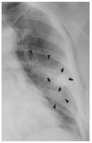 Figure 13.53. Concomitant pulmonary contusion (arrowheads) with a central pulmonary hematoma (curved arrows). |
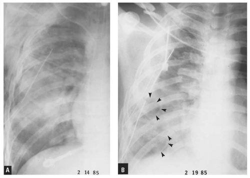 Figure 13.54. Posttraumatic pseudocysts. The initial chest radiograph (A) demonstrates multiple right rib fractures, pneumothorax, extensive pulmonary contusion and subcutaneous emphysema, and various tubes and catheters. On the frontal examination obtained 5 days post-trauma (B), sharply defined, rounded lucent areas with thin walls (arrowheads) are present at the right base. The lucencies represent posttraumatic pseudocysts. |
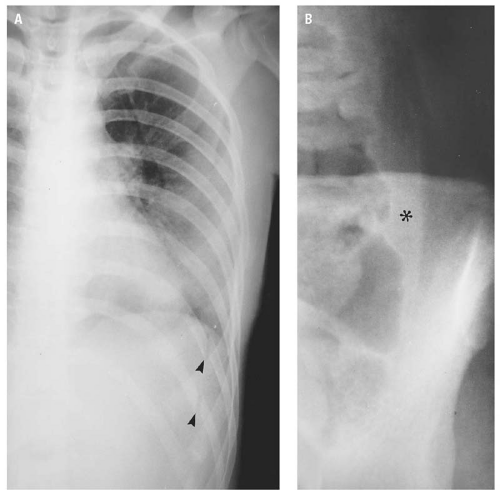 Figure 13.55. The frontal examination of the left hemithorax (A) demonstrates pulmonary contusion at the left base and complete, displaced fractures of the left ninth and tenth ribs (arrowheads) in the posterior axillary line. The left pulmonary contusion should force the observer to a diligent search for rib fracture. The presence of the left lower rib fractures should create a high index of suspicion for intra-abdominal (splenic or left renal) trauma. The frontal examination of the left flank (B) demonstrates medial displacement of the descending colon from the flank stripe by a soft tissue density (asterisk) within the left paracolic gutter. Laparotomy revealed a ruptured spleen and hemoperitoneum. |
Abnormal Intrathoracic Air
This section is devoted to the pathology and radiographic appearance of air in abnormal spaces within the chest (e.g., pneumothorax,
pneumomediastinum, paramediastinal pneumatocele, pneumopericardium). The radiographic appearance of air within these different spaces is peculiar to each, but within each space, the appearance of the air is the same whether the mechanism of injury is traumatic or nontraumatic. Therefore, the radiographic signs of abnormal air collections caused by both traumatic and nontraumatic etiologies are discussed together.
pneumomediastinum, paramediastinal pneumatocele, pneumopericardium). The radiographic appearance of air within these different spaces is peculiar to each, but within each space, the appearance of the air is the same whether the mechanism of injury is traumatic or nontraumatic. Therefore, the radiographic signs of abnormal air collections caused by both traumatic and nontraumatic etiologies are discussed together.
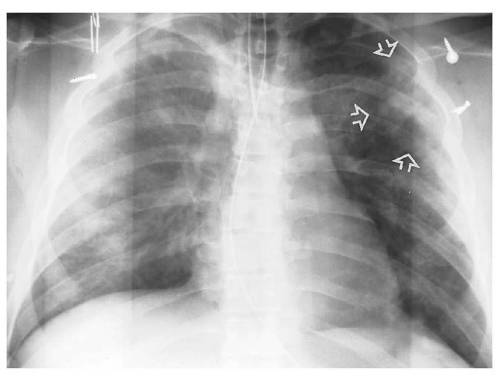 Figure 13.56. Bilateral pulmonary contusion more extensive on the right. The mottled, peripheral parenchymal densities are variable from the right apex to the diaphragm through the density of the transportation board. The distribution of these parenchymal abnormalities indicates that the injury does not respect the anatomic divisions of the lung, which, together with the very peripheral location, is entirely consistent with pulmonary contusion instead of aspiration. Similar but less extensive findings are present in the superolateral aspect of the left upper lobe (open arrows). |
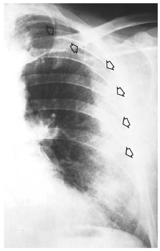 Figure 13.57. The diffuse haziness in the peripheral portion of the left lung represents pulmonary contusion associated with multiple rib fractures (open arrows). |
Pneumothorax
Air in the pleural space is usually the result of blunt or penetrating trauma that causes a tear in the visceral pleura, allowing air to collect within the pleural space. Pneumothorax secondary to blunt trauma most commonly results from a rib fracture that pierces the visceral pleura, but it may result from an abrupt increase in intra-alveolar pressure against a closed glottis with consequent rupture of a bleb or peripheral bulla. “Spontaneous” (nontraumatic) pneumothorax most commonly results from a rupture of alveolar blebs immediately beneath the visceral pleura. In more than 50% of patients, the etiology of the rupture is unknown. Many diseases may be associated with spontaneous pneumothorax, including such disparate conditions as spasmodic asthma, staphylococcal pneumonia, and pulmonary metastatic disease (Fig. 13.58).
A “closed” pneumothorax occurs when the chest wall is intact. An “open” pneumothorax, also referred to as a “sucking” wound of the chest, indicates direct communication between the ambient air and the pleural space. Pneumothorax may
also be classified based on magnitude of collapse as marginal (Fig. 13.35), moderate, or massive (Fig. 13.59).43
also be classified based on magnitude of collapse as marginal (Fig. 13.35), moderate, or massive (Fig. 13.59).43
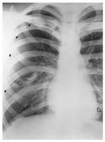 Figure 13.58. Spontaneous pneumothorax (closed arrows) associated with pulmonary metastasis (open arrows) from osteogenic sarcoma in a 17-year-old man. |
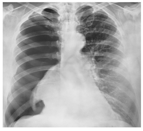 Figure 13.59. Massive right pneumothorax without mediastinal shift. |
Conventional chest radiography—preferably erect PA and lateral projections, but even supine AP CXR—demonstrates most pneumothoraces and is the initial imaging modality of choice for this purpose. “Occult” pneumothorax is discussed subsequently in this section.
The radiographic diagnosis of pneumothorax depends on demonstration of the very thin, curved linear density of the visceral pleura with the lucency of air in the pleural space interposed between the visceral pleura medially and the parietal pleura and chest wall laterally. Obviously, there will be neither parenchymal nor vascular markings beyond the visceral pleura. When the magnitude of collapse is moderate or massive or when an associated hemopneumothorax or hydropneumothorax produces an air-fluid level within the pleural space (Fig. 13.60), the diagnosis is readily apparent.
The diagnosis of marginal pneumothorax may be exceedingly difficult because of superimposed skeletal shadows or the inherent difficulty in perceiving the faint density of the visceral pleural surface. The pneumothorax may be enhanced in a PA radiograph obtained during forced expiration (Figs. 13.6 and 13.61). The basis of this phenomenon is that the collapsed lung decreases in volume during expiration while the air in the pleural space stays constant. Consequently, the lung “falls away” from the chest wall, rendering the pneumothorax more obvious. Other maneuvers to demonstrate pneumothoraces include placing the supine patient in the semierect (Fig. 13.7), erect (Fig. 13.62), or lateral decubitus position with the suspected side up in which event the pleural air will migrate to the uppermost portion of the pleural space. If the patient cannot be moved from the supine position, a horizontal beam lateral CXR may, and CT will, demonstrate air in the anterior pleural space.
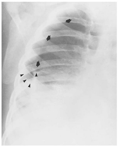 Figure 13.60. Right hydropneumothorax (arrows). The pleural effusion is indicated by the meniscus sign and air-fluid level (arrowheads). |
The “deep sulcus” sign (Fig. 13.63) refers to an increase in the depth and width of the costophrenic angle associated with air in the pleural space and is an extremely valuable sign of a pneumothorax that is not visible on a poor quality radiograph. The deep sulcus sign may be the only indicator of pneumothorax on a supine CXR (Fig. 13.64).
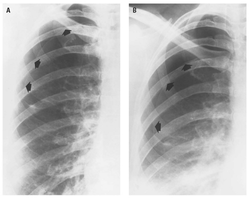 Figure 13.61. Effect of inspiration (A) and expiration (B) on the volume of pneumothorax (arrows). |
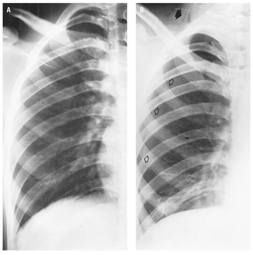 Figure 13.62. Supine examination of the chest (A) of a patient who was stabbed in the posterior right flank is negative. However, the semierect examination of the chest (B) demonstrates a pneumothorax (open arrows), subcutaneous emphysema in the right side of the neck (closed arrow), and subsegmental atelectasis at the right base.
Related posts:Stay updated, free articles. Join our Telegram channel
Full access? Get Clinical Tree
 Get Clinical Tree app for offline access

|