Common Artifacts and Pitfalls of Clinical Echocardiography
CLINICALLY IMPORTANT IMAGING ARTIFACTS RESULT from the interplay of the ultrasound system, the patient, and the interpreting echocardiographer. Knowledge of the types of artifacts that occur during a standard TEE examination is of paramount importance for the correct interpretation of the echo data. The most common artifacts seen in clinical practice are the result of (a) normal or variant anatomic structures that are misdiagnosed, (b) the physical limitations of ultrasound imaging, and (c) undesirable interactions of ultrasound with tissues or medical devices. In this chapter we first review the common false interpretations of normal anatomy. Second, we discuss the artifacts commonly encountered in two-dimensional imaging and three-dimensional imaging, and finally, we discuss the artifacts commonly encountered in Doppler examinations.
NORMAL ANATOMIC VARIANTS IN TWO-DIMENSIONAL IMAGING
Both novice and experienced echocardiographers may call normal structures abnormal. These normal variants can affect the intraoperative diagnosis and lead to an inappropriate surgery, which can have a devastating impact on the outcome. Careful evaluation and a consideration of the common variants discussed in the subsequent text can help limit problems related to misdiagnosis.
Crista Terminalis
The crista terminalis has been misinterpreted as a right atrial tumor or thrombus. This prominent muscular ridge can be differentiated from an anomaly by its characteristic appearance and position. The crista terminalis originates at the junction of the right atrium and superior vena cava and runs longitudinally toward the inferior vena cava. The crista terminalis separates the trabeculated appendage of the atrium from the smooth tubular portion. The structure is best visualized in the midesophageal (ME) bicaval view (Fig. 22.1).
Eustachian Valve or Chiari Network
The Eustachian valve is often misdiagnosed as an intra-atrial thrombus. The Eustachian valve (called a Chiari network when fenestrated) is the remnant of the embryologic right venous valve, which is important in utero to direct inferior vena cava blood flow across the fossa ovalis. The filamentous structures can be differentiated from thrombus by their characteristic “insertion” into the atrial wall. They are best visualized in the ME bicaval view, in which they can be seen originating from the junction of the right atrium and inferior vena cava (Fig. 22.1).
Lipomatous Hypertrophy of the Atrial Septum
Myxomas, the most common cardiac tumors, often originate from the interatrial septum and typically involve the fossa ovalis. Lipomatous hypertrophy of the atrial septum can mimic atrial masses such as myxomas. The characteristic “dumbbell” shape seen in the ME four-chamber or ME bicaval view differentiates lipomatous hypertrophy from other structures. The appearance is caused by fatty infiltration of the atrial septum with sparing of the fossa ovalis (Fig. 22.2).
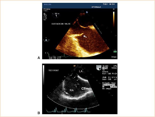
FIGURE 22.1 A: The Eustachian valve is easily seen in this midesophageal bicaval view. B: A prominent Chiari network (arrows). LA, left atrium; RA, right atrium; CT, crista terminalis.
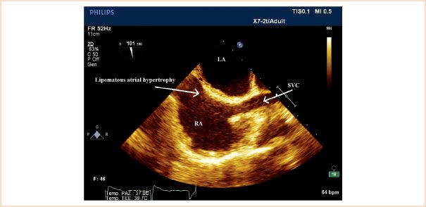
FIGURE 22.2 The characteristic dumbbell shape of a lipomatous atrial septum with sparing of the fossa ovalis is seen in this midesophageal bicaval view. LA, left atrium; RA, right atrium; SVC, superior vena cava.
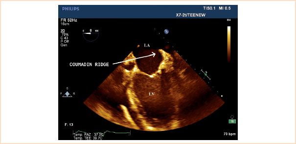
FIGURE 22.3 A Coumadin ridge is seen between the left atrial appendage and the left upper pulmonary vein (LUPV). LA, left atrium; LV, left ventricle.
Coumadin Ridge
A prominent muscle ridge is formed between the left atrial appendage and the atrial insertion of the left upper pulmonary vein. This prominence is often misdiagnosed as thrombus and is referred to as the Coumadin ridge or “Q-tip” sign. The lack of mobility and characteristic location, best seen in the ME two-chamber view, help distinguish it from an abnormal structure (Fig. 22.3).
Pericardial Sinuses
Pericardial sinuses (or folds) between the atria and great vessels can give rise to echolucent spaces despite only minimal amounts of pericardial fluid. The transverse and oblique sinuses of the pericardium can easily mimic pericardial cysts or abscesses. Pericardial fat seen in these extracardiac structures can also mimic intracardiac thrombus (Fig. 22.4).
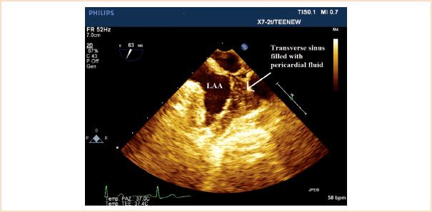
FIGURE 22.4 Transverse sinus filled with pericardial fluid can be seen in this midesophageal view at 60 degrees. LAA, left atrial appendage.
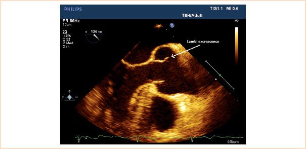
FIGURE 22.5 A Lambl excrescence is seen on the aortic valve (arrow).
Lambl Excrescences
Fine filamentous strands, Lambl excrescences, can be seen originating from the aortic valve of elderly patients. These structures can be differentiated from valvular vegetations by their characteristic “delicate” appearance in the absence of any clinical evidence of endocarditis (Fig. 22.5).
Moderator Band and False Tendon
The moderator band of the right ventricle has been misinterpreted as an intracardiac mass. This specialized cardiac trabeculation runs from the right ventricular free wall to the interventricular septum. It is often best seen in the ME four-chamber view (Fig. 22.6A). In contrast, a false tendon is an anatomic variant of the left ventricle consisting of fibromuscular string(s) coursing from the interventricular septum to the region about the papillary muscles (Fig. 22.6B and Video 22.1). They are best detected in ME longitudinal views and can be mistaken for subaortic membranes and pseudoaneurysm.
Pleural Effusion
Pleural effusions of the left side of the chest can mimic aortic dissection. In the descending aorta long-axis view, a pleural effusion will parallel the course of the aorta and have the appearance of a true lumen–false lumen dissection. Changing to the descending aorta short-axis view and identifying the characteristic triangular shape of a left-sided pleural effusion easily confirm the diagnosis of effusion versus dissection (Fig. 22.7). To inspect for a right-sided pleural effusion the probe is turned progressively leftward from the descending aortic views to examine the right posterior chest.
TWO-DIMENSIONAL ECHOCARDIOGRAPHIC IMAGING ARTIFACTS
Suboptimal Image Quality
The inability to visualize cardiac structures because of suboptimal image quality remains a challenge in transesophageal echocardiographic diagnosis. Most commonly, improper settings of the ultrasound unit are to blame, but patient anatomy, acoustic interfaces (e.g., air between the probe and the stomach or esophageal wall, hiatal hernia), and sonographer skill play a definite role. Adjustments in machine settings coupled with minor manipulations of the ultrasound probe can lead to substantial improvement in to low quality images. This topic is discussed further in Chapter 23.
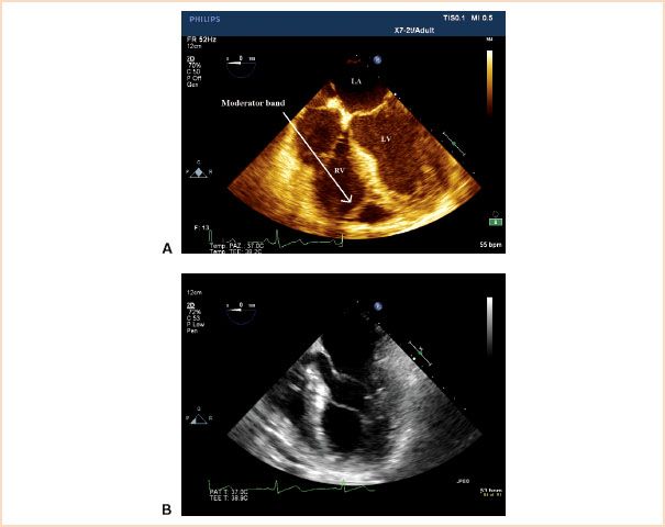
FIGURE 22.6 A: The moderator band of the right ventricle is seen in this midesophageal four-chamber view. B: In contrast, a left ventricular false tendon. LV, left ventricle; RV, right ventricle; LA, left atrium.
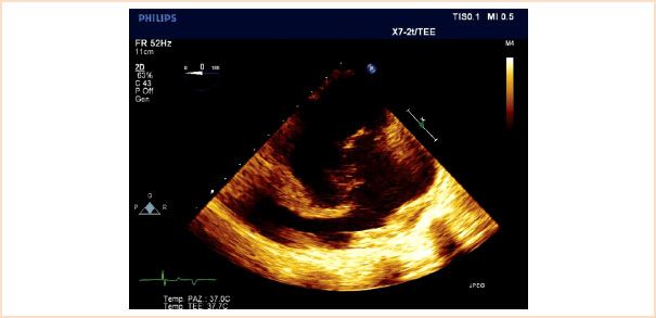
FIGURE 22.7 A pleural effusion is seen in a transverse plane.
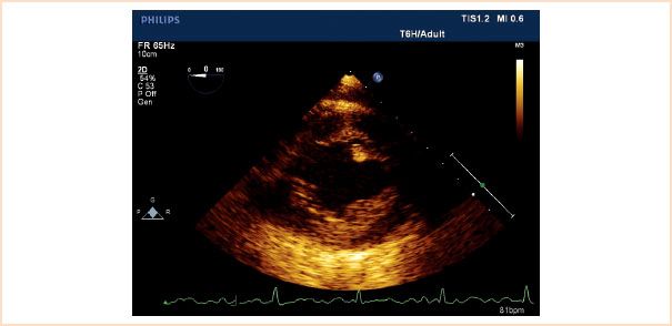
FIGURE 22.8 Transgastric mid short-axis view demonstrating septal and lateral wall dropout.
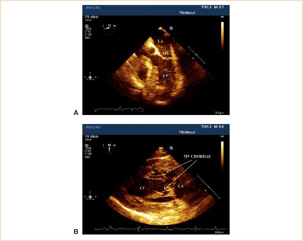
FIGURE 22.9 A: Mitral valve and apparatus imaged with chordae tendineae parallel to the ultrasound beam (midesophageal five-chamber view). B: Markedly improved delineation of the chordae tendineae with the ultrasound beam perpendicular to the chordae tendineae (transgastric long-axis view). LA, left atrium; MV, mitral valve; LV, left ventricle.
Air between the transducer surface and tissue, encountered in transgastric views more often than in transesophageal views, causes severe image degradation to the point of complete inability to image. Gastric suctioning before the transesophageal echocardiographic examination can rectify the poor acoustic transmission caused by an air–tissue interface.
Imaging is also frequently suboptimal when the cardiac structure of interest lies parallel to the ultrasound beam. A common example of this artifact is “dropout” of the lateral and septal walls in the TG short-axis and ME four-chamber views (Fig. 22.8). As specular reflections are maximized when tissue interfaces lie perpendicular to the ultrasound beam, this artifact is best overcome by repositioning the ultrasound probe to a more favorable vantage point. Another example of this phenomenon is the impaired ability to visualize thin linear structures, such as the chordae tendineae of the mitral valve, when they are parallel to the ultrasound beam (ME five-chamber view) (Fig. 22.9A). However, when these structures are interrogated perpendicular to the beam (TG two-chamber view), they are easily visualized (Fig. 22.9B).
Acoustic Shadowing
Acoustic shadowing occurs when the ultrasound beam meets an interface of two structures with marked differences in acoustic impedance. Common examples include structures with a high level of acoustic impedance, such as calcific aortic or mitral valves (Fig. 22.10A).
Such structures strongly reflect and scatter the ultrasound signal, thereby limiting distal penetration of the sound waves. Similarly, mechanical prostheses and the struts of bioprosthetic valves produce shadowing. The resultant image reveals an echo-dense structure with a lack of signal in the sector beyond the structure (Fig. 22.10B).
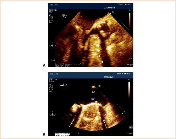
FIGURE 22.10 A: In this view a broad area of the distal scan is not visible due to shadowing from a calcific aortic valve (arrows). B: Acoustic shadowing caused by a prosthetic mitral valve ring imaged in the midesophageal four chamber view. The arrows point to the long axial shadows. LA, left atrium; MV, mitral valve; LV, left ventricle.
Related posts:
Stay updated, free articles. Join our Telegram channel

Full access? Get Clinical Tree


