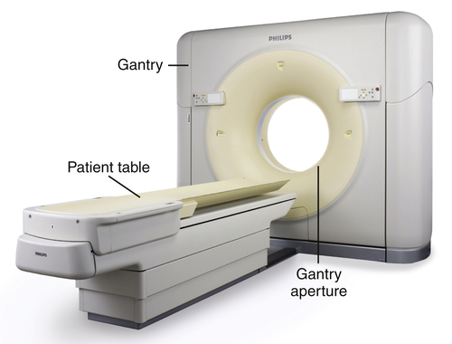
• Identify the major developments in computed tomography (CT) technology, including the five generations of CT equipment, spiral CT, and multislice CT, and explain their effect on CT imaging. • Describe the components of the CT imaging system and explain their functions. • Differentiate between raw and image data. • Identify the characteristics of the CT image, including matrix, pixel, and voxel. • Describe the reconstruction process, following the conversion of raw data to image data. • Differentiate between linear attenuation coefficients and CT numbers. • Based on the Hounsfield scale, identify the CT numbers associated with water, air, and bone. • Identify equipment associated with CT studies. • Describe factors that are set within an examination protocol. • Describe common postprocessing methods. • Explain how window width (WW) and window level (WL) settings determine which pixels in the CT image will be white, black, or a shade of gray. • Explain how WW and WL settings affect the image contrast and brightness. • Describe CT image quality characteristics; identify how image settings affect the quality and their associated tradeoffs. • Identify artifacts associated with CT imaging and explain how they can be reduced or eliminated. • Identify CT quality control tests and their purpose. • Discuss how radiation protection can be practiced for CT imaging, including methods for protecting the patient as well as others remaining in the room. automatic tube current modulation electron-beam computed tomography (EBCT) generations (first through fourth) linear attenuation coefficient multislice computed tomography (MSCT) Introduced in the early 1970s, computed tomography (CT) quickly revolutionized the field of medical imaging. Taking advantage of the development of faster and more powerful computers, CT combines a tightly collimated x-ray beam and detectors that rotate around the patient. X-ray transmission values are measured multiple times as the tube circles the patient and signal data are digitized and sent to the computer (Figure 16-1). Following a large number of calculations, a cross-sectional axial image is reconstructed and displayed. Not only does the resulting image demonstrate minimal superimposition of anatomic structures, the image data are based on the attenuation characteristics of the anatomy being imaged and the image display can be adjusted to distinguish tissues that have x-ray attenuations that differ only slightly (Figure 16-2). The first two generations of CT scanners are considered “translate-rotate” types because the x-ray beam was not wide enough to cover the entire anatomy being imaged. As seen in Figure 16-3, A, first-generation scanners had a pencil-thick x-ray beam and a single detector. The only anatomy that could be imaged was the head because it took approximately 5 minutes to collect the transmission data for one slice. While energized, the x-ray beam and detector had to travel across (translate) the head before it could rotate 1 degree and repeat the process. In that the x-ray beam was pulsed on and off as it moved across the head, the transmission data were collected with parallel-beam geometry. All subsequent CT generations use a fan beam or fan-beam geometry. Second-generation CT scanners (Figure 16-3, B) had a small fan beam and detector array. The unit had only approximately 30 detectors and the fan beam was still not wide enough to cover the anatomy, so translation was still required. However, because more anatomy was imaged at one time, the process had to be repeated only approximately 18 times. Scan time was significantly reduced to approximately 30 seconds. Third- and fourth-generation CT scanners eliminate the need to translate because the fan beam is widened to cover any anatomic area. Both systems collect the data for one slice very quickly, in approximately 1 second or less. The major difference between the third- and fourth-generation scanners is in the detector array. Third-generation scanners (Figure 16-3, C) have a curved array of hundreds of detectors, which are located opposite the x-ray tube and rotate as the tube rotates and pulses. Fourth-generation scanners (Figure 16-3, D) have thousands of fixed detectors in a ring inside the gantry. The tube rotates while continuously emitting radiation, but the detectors do not rotate. The primary advantage of the fourth-generation scanner is that it overcomes a specific third-generation artifact. However, most scanners in use today are based on third-generation technology. Many consider the electron-beam computed tomography (EBCT) scanner to be the fifth generation (Figure 16-4). Developed for cardiac imaging, the EBCT reduces scan time to as little as 50 ms, fast enough to image the beating heart. EBCT does not use an x-ray tube; instead it uses a beam of electrons generated outside the gantry. Inside the gantry there are 180-degree rows of fixed detectors on one side and 180 degrees of tungsten arcs opposite. The electron beam is rapidly moved to bombard the tungsten arcs, producing an x-ray beam. The x-rays then pass through the patient and transmission information is collected by the detectors. These units are very fast because they have no moving parts. For a number of years they were the only scanners fast enough for cardiac imaging. However, two additional developments resulted in significant scan time reduction and minimized the use of EBCTs. Spiral (helical) and multislice (multidetector) CT are more recent CT developments that have had such a dramatic effect on reducing scan time and improving image quality that they are standard on modern CT units. Prior to the late 1980s, conventional CT studies were done in slice-by-slice mode. The patient was placed on the table and moved a certain amount into the bore of the gantry. The pulsing x-ray tube and detectors rotated 360 degrees, collecting data. Once complete, the patient and table were moved incrementally into the scanner and the tube was rewound into its original position. The process was repeated for each slice of the procedure. In the late 1980s CT scanners with slip-ring technology were introduced. Located inside the gantry, the slip-ring technology allowed the tube to continue to rotate without the need to rewind. Continuous rotation of the tube (and detectors) coupled with continuous movement of the table and patient through the gantry are the basic components of spiral (helical) CT (Figure 16-5). Instead of collecting data one slice at a time, spiral CT collects the data for an entire volume of tissue (such as the head or chest) at one time. Scan time is reduced in that the start and stop time of the slice-by-slice scanner is eliminated. The other major development in CT technology is multislice computed tomography (MSCT) used in conjunction with spiral imaging (Figure 16-6). Instead of collecting the transmission data for one slice each time the tube rotates around the patient, MSCT collects data for 4 to 64+ slices per revolution. This is accomplished by opening up the x-ray beam along the Z axis (direction from head to foot) and having a detector array with 4 to 64+ rows. As the number of slices being imaged per revolution increases and the x-ray beam is opened, it goes from being a fan beam to a cone beam. As the cone beam increases in size, the divergence of the x-rays results in increased distortion toward the top and bottom edges. However, spiral MSCT allows overall improved image quality with faster scan time and the ability to perform additional procedures such as CT angiography and cardiac imaging. Modern Scanners Today’s CT system is typically a third-generation, multislice spiral scanner. A CT scanning system includes the scanning unit, the operator’s console, and the computer. The major components of the scanning unit are the gantry and CT table, or couch (Figure 16-7). The gantry contains the equipment that produces the data for image formation. It can be tilted and includes laser beams to determine that the patient is accurately located in the aperture (opening) of the gantry. The CT tabletop may be flat or curved and can be raised and lowered to assist the patient in getting on and off. It has a wide range of horizontal movement, allowing the patient to easily move through the gantry during the scan. Table movement during scanning is controlled by the protocol set at the operator’s console.
Computed Tomography
Introduction
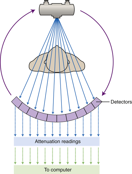
As the x-ray tube and detectors rotate around the patient, the detectors measure the exit radiation multiple times and the digitized attenuation readings data are sent to the computer.
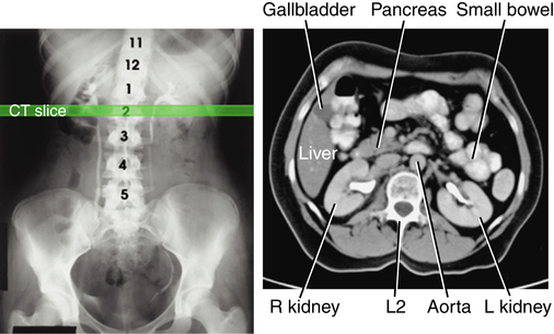
Compared with the radiographic image (left), the computed tomography image is able to visualize abdominal organs and structures that are more similar in tissue density. (From Bontrager KL, Lampignano JP: Textbook of radiographic positioning and related anatomy, ed 7, St Louis, 2010, Mosby.)
Development
Generations
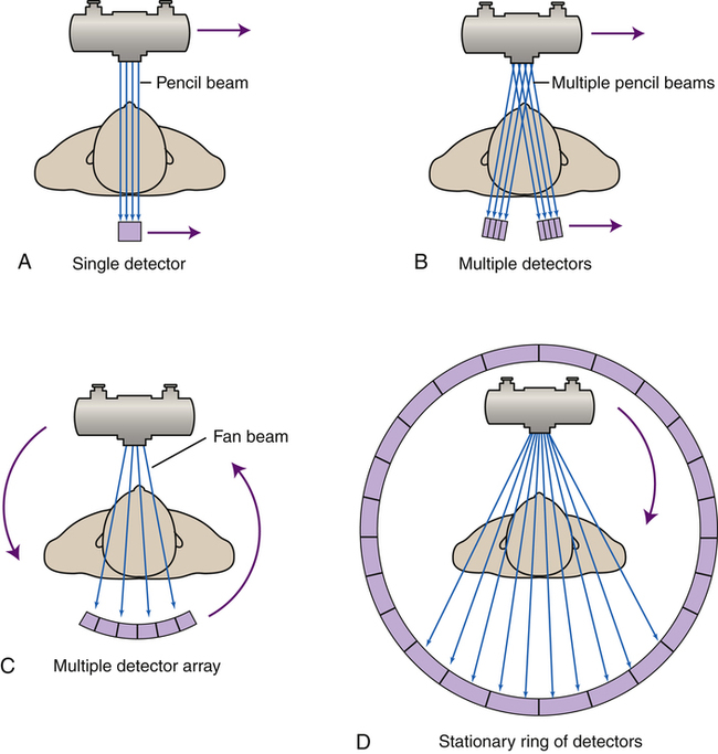
The first four generations of computed tomography scanning methods (first generation [A], second generation [B], third generation [C], and fourth generation [D]) demonstrate how changes in the tube movement and detector configuration have evolved.
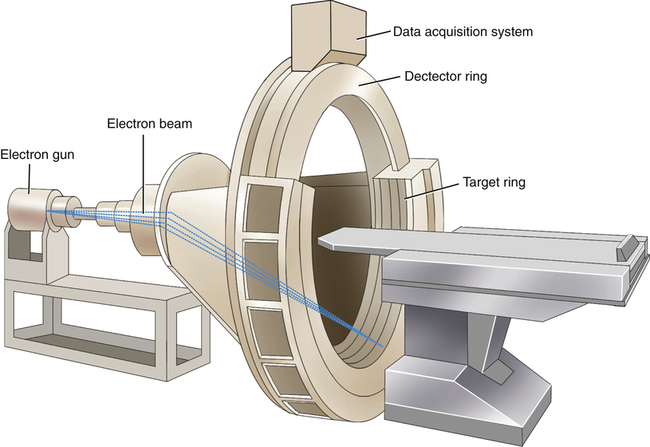
Considered by many to be the fifth generation of computed tomography scanners, electron-beam computed tomography uses an electron gun and tungsten arcs to allow very quick imaging times.
Additional Advancements
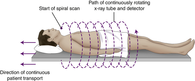
As the patient moves smoothly through the gantry aperture (along the Z axis), the tube and detectors continuously travel around the patient, creating a spiral path.
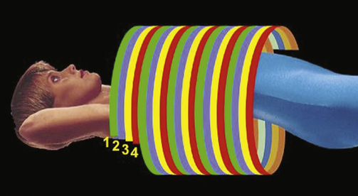
In addition to the spiral method for collecting computed tomography data, having multiple rows of detectors results in four (shown here) or more slices being imaged during each revolution of the tube. (Courtesy Philips Medical Systems.)
 Critical Concept 16-2
Image Data Production
![]()
Stay updated, free articles. Join our Telegram channel

Full access? Get Clinical Tree


Radiology Key
Fastest Radiology Insight Engine
 Critical Concept 16-1