Image Receptors

Chapter 12


Image Receptors


Objectives


• Explain how the latent image is formed.


• Describe film characteristics, including speed, contrast, latitude, and spectral sensitivity.


• Describe the purpose and function of intensifying screens.


• Explain how screens can be characterized based on the type of phosphor, spectral emission, and screen speed.


• Describe factors that affect screen speed.


• State the automatic film processing stages and their function.


• Discuss the purpose of replenishment, recirculation, and temperature control during automatic film processing.


• Identify important quality control measures to ensure good radiographic quality.


• State the importance of and methods for silver recovery.


• Describe the design of cassette-based detectors.


• Describe the design of cassetteless detectors.


• Explain the process of image acquisition using cassette-based detectors.


• Explain the process of image acquisition using the three general types of cassetteless detectors.


• Explain the process of image extraction and processing for cassette-based and cassetteless systems.


• Describe digital image display and postprocessing functions.


• Explain the use of exposure indicators for cassette-based systems and dose-area product for cassetteless systems.


• Correctly identify the role of kVp, mAs, and geometric factors with digital systems.


• Identify quality control tests and test patterns used with digital systems.


• Describe the Picture Archiving and Communication System, including its role, principal systems, and challenges.


Introduction


This chapter covers both film and digital media as image receptors. Radiography is changing. The industry is transitioning from film-screen as the primary image receptor to digital forms. Radiography is the last of the medical imaging modalities to make this transition. Although the transition to digital is almost complete in the United States, we still have facilities that use film-screen and this material is still covered in the American Society of Radiologic Technologists (ASRT) curriculum and on the American Registry of Radiologic Technologists (ARRT) radiography examination. Certainly, the age of film-screen will soon enter the annals of medical imaging history, but for now it remains a part of practice.


As digital radiography establishes its place, new and experienced radiographers alike must learn a few new concepts and practices. But it is equally important that they learn what remains the same. Digital receptors bring many benefits to medical imaging, but they also bring challenges as to how best to use them in the best interest of the patient and the profession.


Radiographic Film


Film Construction


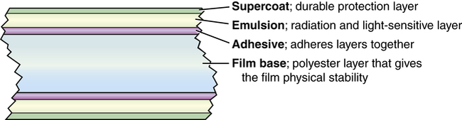
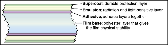
Radiographic film acquires the image and must then be chemically processed before it is visible. As a result, film serves as the medium for image acquisition, processing, and display. Several types of radiographic film are still used in medical imaging departments. Depending on the specific application, film manufacturers produce film in a variety of sizes ranging from 20 × 25 cm (8 × 10 inches) to 35 × 43 cm (14 × 17 inches). The composition of film can be described in layers (Box 12-1). The most important layer for creating the image is the emulsion layer. The emulsion layer is the radiation-sensitive and light-sensitive layer of the film. The emulsion of film consists of silver halide crystals suspended in gelatin. Silver halide is the material that is sensitive to radiation and light. The emulsion layer is fairly fragile and must have a layer composed of a polyester base so that the film can be handled and processed, yet remain physically strong after processing. Most film used in radiographic procedures has a blue dye or tint added to the base layer to decrease eye strain when viewed on a view (illuminator) box.


Screen film is the most widely used radiographic film. As its name implies, it is intended to be used with one or two intensifying screens. Screen film is more sensitive to light and less sensitive to x-rays. Screen film can have either a single- or double-emulsion coating (sometimes referred to as duplitized). Double-emulsion film has an emulsion coating on both sides of the base. Film-screen imaging typically uses double-emulsion film with two intensifying screens.


Single-emulsion screen film, with only one emulsion layer, is used with a single intensifying screen. It has many uses, including duplication, subtraction, computed tomography (CT), magnetic resonance imaging (MRI), sonography, nuclear medicine, mammography, and laser printing.


Latent Image Formation


The term latent image refers to that image that exists on film after that film has been exposed but before it has been chemically processed. Film processing changes the latent image into a manifest image. The term manifest image refers to the image that exists on film after exposure and processing. The manifest image typically is called the radiographic image.


The specific way in which the latent image is formed is not really known, but the Gurney-Mott theory of latent image formation is most widely believed to best explain the manner in which this process happens. To explain latent image formation, it is necessary to describe what happens at the molecular level in the emulsion layer of film, specifically what happens to silver halide crystals when exposed to x-rays and light.


Physical imperfections in the silver halide crystals are the site of the latent image formation and are described in detail in Box 12-2.


BOX 12-2   The Gurney-Mott Theory of Latent Image Formation


Silver halide is made up of both silver bromide and silver iodide. However, because silver bromide (AgBr) is the primary constituent of the silver halide in the emulsion layer of film, only silver bromide is discussed. The process by which the latent image is formed is precisely the same for silver iodide as it is for silver bromide. Silver (Ag) and bromine (Br) are bound together as a molecule in such a way that they share an electron (1). This electron is shared through ionic bonding because silver is a transitional atom, having only one electron in its outer shell, and it tends to either lose it or share it. The silver in AgBr is in effect an ion because it shares only its outer-shell electron with bromine. Energy in the form of x-rays or light is absorbed by the emulsion layers of radiographic film. This energy absorption raises the conductivity level of the electrons in the AgBr molecules, and these electrons move faster as a result. If enough energy is absorbed by a particular AgBr molecule, it becomes a positive ion of silver, neutral bromine, and a free electron (2, 3).


Physical imperfections in the lattice or architecture of the AgBr crystals occur during the film manufacturing process. These imperfections are called sensitivity specks. Each sensitivity speck serves as an electron trap, trapping the electrons lost by the bromine when x-ray or light exposure occurs. Therefore these sensitivity specks become negatively charged (4).


Because the sensitivity specks are negatively charged, the positive silver ions that are liberated from the AgBr molecules are attracted to them (5). Every silver ion that is attracted to an electron becomes neutralized by that electron, therefore becoming metallic silver (6). The more x-ray or light exposure in a particular area of the film, the more electrons and silver available to be attracted to the sensitivity specks. The bromine liberated by x-ray or light exposure is neutral and is simply absorbed into the gelatin of the emulsion.


image

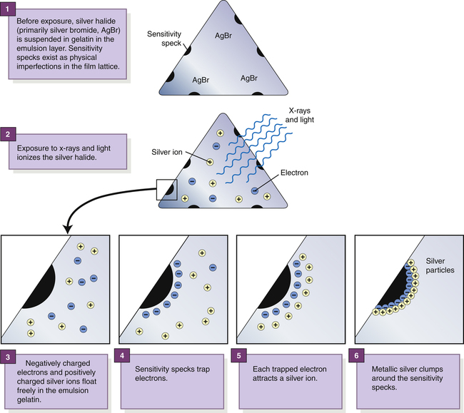
Several sensitivity specks with many silver ions attracted to them become latent image centers. These latent image centers appear as radiographic density on the manifest image after processing. It is believed that for a latent image center to appear, it must contain at least three sensitivity specks that have at least three silver atoms each. With more exposure to the film, more metallic silver is visualized as radiographic density.


Film Characteristics


Current manufacturers of medical imaging film offer a wide variety of films. These differ not only in size and general type, but also in film speed, film contrast, exposure latitude, and spectral sensitivity.


Film Speed


Film speed is the degree to which the emulsion is sensitive to x-rays or light. The greater the speed of a film, the more sensitive it is. Because sensitivity increases, less exposure is necessary to produce a specific density. Two primary factors, both relating to the silver halide crystals found in the emulsion layers, affect the speed of radiographic film. The first factor is the number of silver halide crystals present, and the second factor is the size of these silver halide crystals. Radiographic film manufacturers manipulate film speed by manipulating both of these factors in the production of specific speeds of radiographic film.


Film Contrast and Film Latitude

Film contrast refers to the ability of radiographic film to provide a certain level of image contrast. High-contrast film accentuates more black and white areas, whereas low-contrast film primarily shows shades of gray. As discussed in Chapter 9, film latitude is closely related to film contrast. The latitude of film affects the range of radiation exposures that can provide diagnostic optical densities. Films manufactured to display higher contrast have a narrow exposure latitude compared with low-contrast films having a wider exposure latitude.


Spectral Sensitivity

Spectral sensitivity refers to the color of light to which a particular film is most sensitive. In radiography, there are generally two categories of spectral sensitivity films: blue-sensitive and green-sensitive (orthochromatic). When radiographic film is used with intensifying screens, it is important to match the spectral sensitivity of the film with the spectral emission of the screens. Spectral emission refers to the color of light produced by a particular intensifying screen. In radiography, two categories of spectral emission generally exist: blue light–emitting screens and green light–emitting screens. It is critical to use blue-sensitive film with blue light–emitting screens and green-sensitive film with green light–emitting screens. Spectral matching refers to correctly matching the color sensitivity of the film to the color emission of the intensifying screen. An incorrect match of film and screens based on spectral emission and sensitivity results in radiographs that display inappropriate levels of radiographic density.


Intensifying Screen Characteristics


An intensifying screen is a device found in radiographic cassettes that contains phosphors that convert x-ray energy into light, which then exposes the radiographic film. Its purpose is to intensify the action of the x-rays and thus permit much lower x-ray exposures compared with film alone.


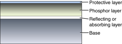
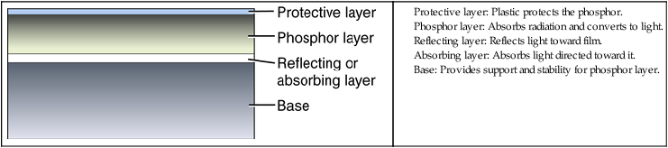
As with radiographic film, the construction of screens can be described in layers (Box 12-3). The phosphor layer, or active layer, is the most important screen component because it contains the phosphor material that absorbs the transmitted x-rays and converts them to visible light. The most common phosphor materials consist of chemical compounds of elements from the rare earth group of elements. Rare earth elements are those that range in atomic number from 57 to 71 on the periodic table of the elements; they are referred to as rare earth elements because they are relatively difficult and expensive to extract from the earth.


Intensifying screen systems used in cassettes generally include two screens. The screen that is mounted in the side of the cassette facing the x-ray tube is called the front screen, and the screen that is mounted in the opposite side is called the back screen. With two screens, the film (double-emulsion) is exposed to approximately twice as much light as a single-screen system because the film is exposed to light from both sides. Some screen systems use only a single screen and are used with single-emulsion film. When a single screen is used, it is mounted as a back screen on the side of the cassette that is opposite from the tube side. When loading a single-emulsion film into the appropriate cassette with a single screen, the emulsion side of the film must be placed against the intensifying screen.


Film is much more sensitive to visible light than to x-rays. By converting each absorbed high-energy x-ray photon into thousands of visible light photons, intensifying screens amplify film optical density. Without screens, the total amount of energy to which the film is exposed consists of only x-rays. With screens, the total amount of energy to which the film is exposed is divided between x-rays and light. When intensifying screens are used, approximately 90% to 99% of the total energy to which the film is exposed is light. X-rays account for the remaining 1% to 10% of the energy.


Intensifying screens operate by a process known as luminescence.Luminescence is the emission of light from the screen when stimulated by radiation. The desired type of luminescence in imaging is fluorescence.Fluorescence refers to the ability of phosphors to emit visible light only while exposed to x-rays.


Screen Speed

The purpose of intensifying screens is to decrease the radiation dose to the patient. Because screen phosphors can intensify the action of the x-rays by converting them to visible light, the use of screens allows the radiographer to use considerably lower mAs. The disadvantage of using screens is the reduction in recorded detail.


Screen manufacturers produce a variety of intensifying screens, which differ in how well they intensify the action of the x-rays and therefore differ in their capacity to produce accurate recorded detail.


The capability of a screen to produce visible light is called screen speed. A faster screen produces more light than a slower screen given the same exposure. Although very fast screens reduce patient exposure, they also degrade image resolution and increase quantum noise, so a balance must be chosen.


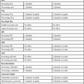
Several factors affect how fast or slow an intensifying screen is, including absorption efficiency, conversion efficiency, thickness of the phosphor layer, and size of the phosphor crystal (Table 12-1). The presence of a reflecting layer, an absorbing layer, or dye in the phosphor layer also affects screen speed.


Absorption efficiency refers to the screen’s ability to absorb the incident x-ray photons. A rare earth phosphor screen absorbs approximately 60% of the incident photons. Conversion efficiency describes how well the screen phosphor takes these x-ray photons and converts them to visible light. Increased absorption and conversion efficiency mean that rare earth phosphors have increased speed when compared with a previously used screen phosphor, calcium tungstate. This increased speed allows the radiographer to substantially reduce the x-ray exposure needed to produce images with the appropriate amount of density.


The thickness of the phosphor layer and the size of the crystal also have an effect on screen speed. A thicker phosphor layer contains more phosphor material than a thinner phosphor layer. The phosphor is the material that converts x-rays into light, so if more phosphor material is present in a screen, more light will be produced, increasing the screen speed. The size of the phosphor material crystals also affects screen speed. Larger phosphor crystals produce more light than smaller phosphor crystals. Again, more light being produced means that the screen is faster.


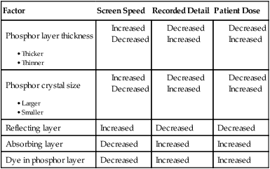
The final factors that affect screen speed are the presence or absence of a reflecting layer, a light-absorbing layer, or light-absorbing dyes in the phosphor layer. A reflecting layer is used to increase screen speed by reflecting light back toward the film (Figure 12-1). A light-absorbing layer or light-absorbing dyes present in the phosphor layer are used to decrease screen speed by absorbing light that would otherwise reach and expose the film.
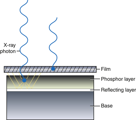


The ability of the screen to produce visible light can also be described in terms of its relative speed. Relative speed results from comparing screen-film systems based on the amount of light produced for a given exposure. Most radiology departments that use film-screen technology have at least two different speeds of intensifying screen systems. A fast system usually is available with a relative speed of about 400. A 400-speed system is a good compromise between the beneficial effect of decreasing the patient dose and the detrimental effect of decreasing the recorded detail. A slower system is usually available, and it is sometimes labeled on the outside of the cassette as detail or extremity. The relative speed of this system typically is 100. Detail or extremity screen systems are relatively slow, and therefore require greater exposure and result in higher patient doses. However, the anatomic parts imaged with detail or extremity screen systems generally are small; therefore they do not require large exposures. Detail or extremity screen systems produce excellent recorded detail. The radiographer must be careful in selecting the appropriate screen system for the examination ordered. Cassettes with extremity and detail screens should be used only for tabletop examinations. They should never be used in the Bucky tray because of the excessive amount of exposure needed.


Screen Maintenance

The maintenance of intensifying screens is significant because radiographic quality depends in large part on how well the screens are continuously maintained. Two important maintenance procedures should be performed on intensifying screens. The first is regular cleaning. The outside surface of screens comes into contact with the environment and with the hands of those unloading and loading cassettes, which results in the natural oils on fingers and hands being deposited on the screen surface. These oils tend to attract dust and dirt, which can build up to the point at which they are actually imaged on radiographs as artifacts. Screen cleaning should be done routinely. The cleaning is accomplished with commercially available antistatic intensifying screen cleaner fluid and gauze pads.


The second important maintenance procedure is to check cassettes for film-screen contact. Good film-screen contact exists when the screen or screens are in direct contact with the film. Poor film-screen contact greatly degrades recorded detail and is usually seen as a localized area of unsharpness somewhere on the radiographic image. Rarely is film-screen contact so poor that unsharpness can be seen across the entire radiograph. A major part of testing for film-screen contact is identifying problem cassettes.


The film-screen contact test is easily accomplished, but it requires a special wire mesh test tool. The wire mesh tool is placed on the cassette in question and radiographed with an appropriate technique. The resultant radiograph (Figure 12-2) is then viewed from a distance of approximately 6 feet to determine any areas of unsharpness, which indicate poor recorded detail. Areas of poor contact appear darker than areas of good contact because of the increased spreading of the light photons.
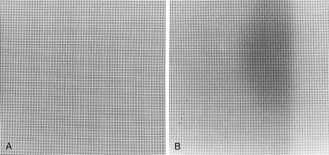


The remaining component in the film-screen image receptor is the cassette. Serving as a container for both the intensifying screens and the film, the cassette must be light-proof, lightweight for portability, and rigid enough not to bend under a patient’s weight, all while allowing the maximum amount of radiation to pass through and reach the screens. Low x-ray–absorbing materials, such as thermoset plastic, magnesium, or even graphite carbon, can be found in the front of cassettes. Inside the back of cassettes may be a thin sheet of lead foil designed to absorb backscatter before it exposes the film.


Automatic Film Processing


The purpose of radiographic processing is to convert the latent image into a manifest image. The manifest image is the image that exists on the film after processing.


According to the Gurney-Mott theory, this process is the first step toward creating a visible image on radiographic film. Exposure of the silver bromide crystal in the film emulsion by light or x-ray photons initiates the conversion process. Chemical processing of the exposed film completes the conversion process and transforms the image into a permanent visible image.


Components


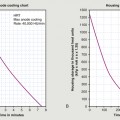
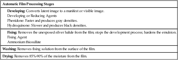
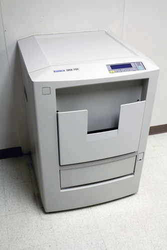
An automatic film processor (Figure 12-3) is a device that encompasses chemical tanks, a roller transport system, and a dryer system for the processing of radiographic film. The processing of a radiograph occurs in four stages: developing, fixing, washing, and drying. Each stage has its specific function and processing method (Table 12-2).


Developing

The primary function of developing is to convert the latent image into a manifest, or visible, image. The purpose of the developing or reducing agents is to reduce exposed silver halide to metallic silver and to add electrons to exposed silver halide. Two chemicals are used to accomplish this purpose: phenidone and hydroquinone. Phenidone is said to be a fast reducer, producing gray (lower) densities. Hydroquinone is said to be a slow reducer, producing black (higher) densities.


Both phenidone and hydroquinone also act to soften and swell the emulsion layers. Phenidone and hydroquinone are said to be synergistic, or to have superadditivity. Superadditivity means that together these chemicals produce a greater effect on the film than they would individually. This is used to advantage by using both chemicals in combination to develop or reduce the exposed silver halide. The developer solution needs an alkaline pH environment for the chemicals to function properly.


During the development process, developer solution donates additional electrons to the sensitivity specks, or electron traps, in the emulsion layers of the film. These additional electrons attract more silver to these areas, thereby amplifying the amount of atomic silver at each latent image center. Exposed silver halide is reduced to metallic silver when bromide and iodide ions are removed from the emulsion. The atomic silver that was exposed to radiant energy (light and x-rays) is converted to metallic silver and presented as radiographic densities. Unexposed silver halide does not react immediately to developer because it has not been ionized and does not accept electrons from the developer. Given extended exposure to developing solution or exposure to excessively heated developing solution, however, even unexposed areas of film can react to developing solution. Exposed silver halide reacts to developer by accepting electrons because neutral atomic silver that was previously bonded to either bromide or iodide has room to accept electrons in its outermost electron shell (the O shell).


Fixing

The primary functions of the fixing stage are to remove unexposed silver halide from the film and to make the remaining image permanent. There are also two secondary functions of fixing. One is to stop the development process; the other is to further harden the emulsions. Fixing solution must function to remove all undeveloped silver halide while not affecting the metallic silver image.


The purpose of the fixing agent is to clear undeveloped silver halide from the film. A thiosulfate (sometimes also called hypo), such as ammonium thiosulfate, is the chemical used as this agent. The fixer solution needs an acidic pH environment for the chemicals to function properly.


Washing

The purpose of the washing process is to remove fixing solution from the surface of the film. This is a further step in making the manifest image permanent. If not properly washed, the resulting radiograph shows a brown staining of the image, resulting in image loss and a decrease in its diagnostic value. This staining is caused by thiosulfate (fixing agent) that remains in the emulsion layers. Some thiosulfate always remains within the film, but the goal of washing is to remove enough so that the radiograph can be used for an extended period.


The process by which washing works is referred to as diffusion. Diffusion exposes the film to water that contains less thiosulfate than the film. Because the film contains more fixing agent than the water, the fixing agent diffuses into the water.


Eventually, thiosulfate concentrations in the wash water can become greater than those in the films being processed; therefore the wash water must be replaced frequently. Water flows freely from the input water supply through the wash tank and down the drain while the roller transport system is operating. This type of system provides a constant supply of fresh wash water to aid in the diffusion process. The moving water also causes agitation and increases diffusion.


Drying

The final process in automatic processing is drying. The purpose of drying films is to remove 85% to 90% of the moisture from the film so that it can be handled easily and stored while maintaining the quality of the diagnostic image. As a result, finished radiographs should retain 10% to 15% of their moisture when processing is complete. If films are dried excessively, the emulsion layers can crack, which decreases the diagnostic quality of the radiograph.


Increased relative humidity decreases the efficiency of dryers in processors, so an increased drying temperature is necessary. Processors are equipped with thermostatic controls to allow selection of a wide range of dryer temperatures.


To chemically process a radiographic image, specialized equipment and systems must perform concurrently to move the film through the processing stages according to the manufacturer’s specifications.


Feb 27, 2016 | Posted by in GENERAL RADIOLOGY | Comments Off on Image Receptors

Full access? Get Clinical Tree

Get Clinical Tree app for offline access