Inflow Refreshment Angiography
Mark Doyle
OVERVIEW
Inflow refreshment is a means of achieving bright blood signal, especially for angiographic purposes. The basic mechanism relies on the physical displacement of blood, which quite literally introduces fresh blood signal between slice selective radiofrequency (RF) pulses. The means of applying this in two-dimensional (2D) and 3D imaging will be discussed.
INFLOW REFRESHMENT MECHANISM
In standard imaging, the signal of interest is usually not the signal produced by an isolated RF pulse, but the signal resulting from a train of RF pulses, that is, under conditions of dynamic equilibrium. Following each RF excitation, the magnetization vector, M0, relaxes back to alignment with B0 by the T1 relaxation process. The strength of the transverse signal following a train of RF pulses depends on the imaging parameters and the intrinsic properties of the body:
The optimum equilibrium signal for static tissue is achieved when the Ernst angle is applied. Using a larger flip angle results in a lower equilibrium signal, that is, a degree of signal suppression is achieved. This feature is exploited in 2D time of flight (TOF) or inflow refreshment imaging, to preferentially suppress static tissue.
FLOW REFRESHMENT
Flowing blood that continuously refreshes the imaging plane does not achieve the equilibrium signal reached by the static tissue, and therefore appears as a relatively bright signal (see Fig. 19-1). This is the basis of the inflow refreshment phenomenon:
Enhancement of blood signal by virtue of it refreshing the imaging plane
This so-called TOF mechanism relies on blood spins physically refreshing the imaging plane and exiting the plane rapidly, and thereby avoids becoming suppressed in the manner of static tissue signal.
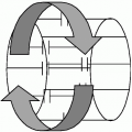
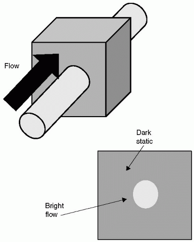 FIGURE 19-1 Blood flow that traverses the imaging slice at a faster rate than the imaging repetition time (TR) results in fresh blood being excited for each application of the basic imaging sequence. Consequently, flow appears bright, because it essentially contributes a fresh signal for each RF pulse experienced. Conversely, static tissue within the slice, after experiencing a train of RF pulses, will become partially saturated, and suffer loss of signal. This is the basis of the inflow refreshment phenomenon. |
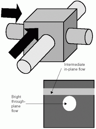 FIGURE 19-2 Blood flow that travels predominantly within the imaging plane (short arrow), fails to completely refresh the plane during each repetition time (TR) interval, and consequently experiences multiple radiofrequency (RF) pulses before exiting the imaging plane. The signal from this blood flow is therefore lower in intensity compared to the more rapid through-plane flow, and may become isointense with the static tissue signal. |
IN-PLANE FLOW SIGNAL
Flow refreshment is incomplete if the flowing blood has a long residency time in the imaged slice. This occurs primarily under the following three conditions:
A large in-plane flow component is present
Slow flow conditions dominate
Flow which reverses in direction and retraverses the image plane
Under these conditions blood clears the plane slowly, and therefore experiences multiple RF pulses, serving to reduce the signal contribution from flow.
TIME OF FLIGHT ACQUISITION
In the 2D TOF acquisition, each slice is fully acquired before advancing to the next slice location. In this way, extended coverage of the body is achieved by performing multiple slices, sufficient to cover the region of interest. In general, the slices are oriented orthogonal to the major direction of flow. Rapid through-plane flow generally appears bright, whereas in-plane flow or slow through-plane flow appears darker or even isointense with the static tissue (see Fig. 19-2). Signal saturation is particularly problematic for the following:
Tortuous vessels
Thick slab 3D imaging
Slow flow near boundary walls
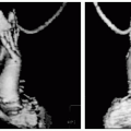
In-plane signal loss is known to be problematic for certain body regions, such as the carotid arteries where they undergo an excursion perpendicular to the main axis of the neck. However, for regions where blood flow is sufficient to refresh each slice, contrast can be very good (see Fig. 19-3). In the abdomen, respiration and peristaltic motion can result in some residual “static” tissue signal, which may obscure arteries when vessel rendering on the basis of signal brightness is used.
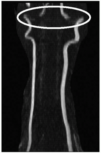 FIGURE 19-3 An example of signal loss attributable to the blood vessel path presenting a higher in-plane competent relative to the imaging slice. In this example of the carotid arteries, most vessels are bright, exhibiting high contrast where flow is perpendicular to the imaging slice, but contrast is diminished (circle
Get Clinical Tree app for offline access
Stay updated, free articles. Join our Telegram channel
Full access? Get Clinical Tree


|
