Fig. 1.
Photograph of a pig lying head first, supine, on the scanner patient table in front of a 1.5-T MR system. The animal is covered by two BodyMatrix RF surface coils. Large in-room display of the real-time images is provided by a large format backprojection screen in conjunction with a video beamer that is contained in an RF-shielded box.
Fig. 2.
Schematic diagram for the ventilation and monitoring setup for experiments in the MR scanner room. All equipment for ventilation and monitoring is placed outside the MR scanner room. Connection to the animal inside the scanner requires long ventilation tubing and connection tubing. (Redrawn from (10).)
2.2 Interventional Vascular Devices
1.
Guidewire, 0.89 mm diameter, 260 cm length, with hydrophilic coating and nitinol core (Terumo Standard Glidewire; Terumo Medical Corporation, Somerset, NJ, USA) for introduction of the introducer sheath (see below) with dilator into the iliac artery (see Notes 3 and 4).
2.
Introducer sheath with silicon pinch valve, inner diameter of 6 mm, free length of 300 mm for introduction into the artery, overall length of 700 mm with dilator (Gore Introducer Sheath; W.L. Gore Inc., Flagstaff, AZ, USA).
3.
Thoracic aortic stent-graft endoprosthesis (100 mm length, 26 mm diameter) made from self-expanding nitinol wire covered with an expanded polytetrafluoroethylene (ePTFE) membrane (GoreTAG; W.L. Gore Inc., Flagstaff, AZ, USA). The loaded stent-graft is constrained by an implantable ePTFE sleeve on the leading end of an 18-French (equates to 6.0 mm diameter) polyurethane delivery catheter. Middle-to-end deployment is initiated by retraction of a GoreTex filament, which rapidly releases the stent-graft from the ePTFE sleeve (see Fig. 3).
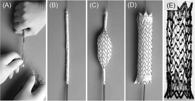
Fig. 3.
Photographs of the GoreTAG stent-graft. (a) Trailing end of the stent-graft delivery device shows position of the guidewire as well as the Gore filament that can be manually pulled to release the loaded stent-graft at the distal end of the delivery device (see b). (b) The stent-graft loaded on the 18-Fr polyurethane delivery catheter and covered by the Gore membrane. (c) The graft is released in a fraction of a second by manually retracting a Gore filament (see a) string that prevents the graft from unfolding. (d) The fully expanded nitinol-based, membrane-covered stent-graft. (e) Minimal-intensity projection of the fully expanded GoreTAG stent-graft acquired with a high-resolution 3D FLASH sequence in a water phantom. The lumen of the stent is free of artefacts thus allowing for detailed evaluation of the stent lumen and surroundings.
2.3 Animal Preparation and Anaesthesia
1.
Domestic pigs (60–90 kg depending on application) that will be sedated and fully anaesthetized (see Note 5).
2.
Sedation is performed with intramuscular injection of ketamine hydrochloride (30 mg/kg), azaperone (2 mg/kg), and atropine (0.025 mg/kg).
3.
Intravenous access in ear vein with 18-gauge cannula.
4.
Anaesthesia is maintained by continuous intravenous infusion of propofol (160 mg/h), fentanyl (0.4 mg/h), and midazolam (40 mg/h).
5.
Infusion pump for anaesthesia (Perfusor Compact; Braun, Melsungen, Germany) (see Note 1).
6.
Endotracheal tube (5.0–8.0 mm inner diameter) for animal ventilation.
7.
Respirator for ventilation (Oxylog; Dräger, Lübeck, Germany) (see Note 1).
8.
Monitoring of heart rate with a four-channel ECG unit of an MR scanner (Siemens Healthcare Sector, Erlangen, Germany).
9.
Monitoring of oxygenation with peripheral oxygen sensor (Vet/Ox 4404 pulse oximeter; Heska Animal Health Products, Clayton, Australia) (see Note 1).
10.
Contrast-enhanced MR-angiography (MRA) with Gd-DTPA (Magnevist; Bayer Schering, Berlin, Germany) or Gd-DOTA (Dotarem; Guerbet, Cedex, France).
11.
Euthanization with bolus injection of pentobarbital (80 mg/kg).
2.4 Interventional MR Imaging and Sequences
MR imaging is comprised of pre-interventional diagnostic imaging, real-time MR image guidance, and post-interventional imaging of therapeutic success. Image sequences are listed with imaging parameters. The abbreviations used are as follows: FOV, field of view; TR, repetition time; TE, echo time; slice, slice thickness; BW, bandwidth; flip, flip angle; and TA, acquisition time.
1.
Localizer imaging (TrueFISP sequence: TR = 4 ms, TE = 2 ms, FOV = 400 × 400 mm, matrix = 192 × 192 pixel, slice = 8 mm, flip = 70°, providing 3 slices for each of the basic orientations (axial, coronal, sagittal)) provides fast anatomic overview and anatomic landmarks.
2.
Cine-TrueFISP retro, ECG-gated, respiration-suspended, retrospective image reconstruction (TrueFISP sequence: TR = 40 ms, TE = 1.1 ms, FOV = 380 × 330 mm, matrix = 192 × 168, slice = 6 mm, BW = 930 Hz/pixel, flip = 70°, TA = 15 s, 20 imaging phases/RR-interval, parasagittal orientation along the aortic arch and axial to the course of the aorta) for cardiac-gated pre- and post-interventional evaluation of aortic pathology.
3.
Test bolus timing (Fast gradient echo (GRE) sequence: TR = 34.1 ms, TE = 1.2 ms, FOV = 400 × 400 mm, matrix = 256 × 192, slice = 10 mm, BW = 400 Hz/pixel, flip = 30°, 60 measurements providing 1 image/s) in axial orientation for determination of the contrast arrival time in the vessel segment of interest (aorta) when planning first-pass arterial MR angiography (MRA).
4.
Contrast-enhanced (CE) 3D MR angiography (FLASH sequence: TR = 2.5 ms, TE = 1.0 ms, FOV = 400 × 400 mm, matrix = 384 × 246, slab thickness of 154 mm, 128 slices with an interpolated slice thickness of 1.2 mm, BW = 685 Hz/pixel, flip = 15°, TA = 18 s, coronal orientation) for pre- and post-interventional angiographic display of the vascular lumen.
5.
Interactive real-time TrueFISP (TrueFISP sequence with projection reconstruction (PR): TR = 3.0 ms, TE = 1.5 ms, FOV = 360 × 360 mm, matrix = 192 × 192, slice = 6 mm, BW = 1530 Hz/pixel, 49 echoes were acquired for each reconstructed image, resulting in a “real-time” frame rate of 7 fps) (see Notes 6, 7, and 8).
6.
Post-contrast T 1-weighted VIBE (VIBE sequence: TR = 3.1 ms, TE = 1.3 ms, FOV = 400 × 400 mm, matrix 256 × 134, slice = 3 mm, BW = 560 Hz/pixel, flip = 20°, fat saturation, 128 slices acquired in 21 s) to confirm for post-interventional thrombus formation in false lumen of dissection and to perform contrast-enhanced MRA after application of a paramagnetic contrast agent (Gd-DTPA or Gd-DOTA), as well as post-contrast evaluation of thrombus formation in the false lumen.
3 Methods
Before the actual interventional procedure can be performed, the MRI scanner has to be prepared for the experiment (Section 3.1). The stent-graft delivery device with its introducer sheath is prepared for vascular introduction (Section 3.2). The animal will be sedated and prepared for anaesthesia (Section 3.3). Surgical preparation for vascular access is performed (Section 3.3.1). Finally, the animal is brought to the interventional MR scanner suite and prepared for MR imaging. The MR imaging section (Section 3.4) describes the chronologic order of the imaging protocol with all the sequences used for pre-interventional diagnostics, interventional real-time instrument guidance, and post-interventional evaluation of therapeutic success.
3.1 Interventional MR Scanner Setup
1.
The RF coils used in the experiment are prepared for use in an animal intervention. The SpineArray RF coil is placed on the patient table of the MR scanner. The SpineArray coil is covered with paper covers. Two BodyArray RF coils are covered with plastic bags to protect the coils from contact with body fluids.
2.
The mobile in-room console is placed next to the scanner such that the operator can run the scanner with keyboard commands from inside and such that the interventionalist simultaneously can monitor the course of the intervention on the 18” monitor.
3.
The large format in-room backprojection screen with the RF-shielded video beamer is placed in the scanner room such that everybody in the operation room can monitor and follow the course of the intervention (see Fig. 1).
4.
All imaging sequences are stored in accordance with the imaging parameters provided in Section 2.4 Imaging sequences are stored in chronological order to form an imaging protocol according to the imaging workflow. The localizer sequences are opened first.
3.2 Interventional Vascular Devices
1.
The 18-Fr dilator is introduced with its leading end through the silicone pinch valve into the Gore introducer sheath.
3.3 Animal Preparation and Anaesthesia
1.
Initial sedation of the animals is achieved by intramuscular injection of ketamine hydrochloride (30 mg/kg), azaperone (2 mg/kg), and atropine (0.025 mg/kg) vertically into the animal’s neck (see Note 9).
2.
Intravenous access is achieved by insertion of an 18-gauge cannula into an ear vein.
3.
Anaesthesia is induced by venous bolus injection of propofol (2 mg/kg BW) and fentanyl (0.005 mg/kg BW).
4.
Endotracheal intubation is performed in prone position of the animal on the operation table. An assisting person opens the snout by means of a gauze bandage applied to the animal’s upper and lower jaws. Swallowing reflex is completely defunct. Tube sizes range from 5.0 to 8.0 mm depending on the size of the pig. After pre-oxygenation with 100% O2, the tongue is carefully put into a forward position. When palate and palatal velum become visible, the tube can be lead in under eye contact toward the epiglottis and carefully pushed forward simultaneously rotating it round its axis.
5.
The animal is ventilated with a respirator (Oxylog) using 50% oxygen and a ventilation rate between 10 and 12 breaths/min. The tidal volume varies between 600 and 1000 mL depending on the weight of the pig. Pre-oxygenation using 100% oxygen is performed prior to each induction of apnea.
6.
Monitoring includes heart rate and ECG via external leads, oxygenation via peripheral oxygen sensor at the pig’s tail, and respiration via external chest sensors.
7.
Anaesthesia is maintained by continuous intravenous infusion of an initial dose of propofol of 2.29 mg/kg BW/h, midazolam of 1.14 mg/kg BW/h, and fentanyl of 0.009 mg/kg BW/h delivered via infusion pump (Perfusor Compact) (see Note 10).
8.
For MR procedures, the potentially ferromagnetic infusion pumps and the respirator are placed outside the scanner room. For connections to the animal lying in the isocentre of the magnet, a ventilation tube and connector tubing 6 m in length – depending on the room size and setup – have to be used (see Note 1).
3.3.1 Surgical Animal Preparation
1.
A paramedian incision of the left groin is performed to expose the left iliac artery. For that, the iliacal muscles are dissected bluntly and the underlying iliac artery is laid open.
2.
The Terumo guidewire is introduced into the iliac artery and pushed forward to be located with its leading end into the abdominal aorta of the animal.
3.
The Gore introducer sheath with the 18-Fr dilator in place is gently shifted with its leading end over the trailing end of the guidewire. The catheter sheath is subcutaneously tunnelled up into groin area over the guidewire until the leading end of the catheter sheath is safely positioned within the aorta of the animal.
4.
All skin lesions and the bluntly dissected muscles are closed by single-stitch technique. The animal is then transported to the MR scanner unit (see Note 11) by the interventional team (see Note 12).
5.
 Spin Echo BOLD fMRI on Songbirds
 MR for the Investigation of Murine Vasculature
 Analysis of Freshly Fixed and Museum Invertebrate Specimens Using High-Resolution, High-Throughput MRI
 MRI Using Intermolecular Multiple-Quantum Coherences
 MRI of CEST-Based Reporter Gene
 Hyperpolarized Molecules in Solution


The animal is placed head first in a supine position inside the scanner on the paper-covered spine phased-array radio frequency (RF) coil with three clusters of coil elements activated for signal reception. For ECG electrode placement, the animal’s chest is shaved with a disposable shaver and contact gel is used to assure good electrode-to-skin contact. The ECG trigger unit of the MR scanner is connected to the electrodes. Two body flex phased-array RF coils, each consisting of two clusters of coil elements, are placed anteriorly on the pig. The legs of the animal are fixed with bandages to the scanner table in order to result in a stable position (see Fig. 1).
Related posts:
Spin Echo BOLD fMRI on Songbirds
MR for the Investigation of Murine Vasculature
Analysis of Freshly Fixed and Museum Invertebrate Specimens Using High-Resolution, High-Throughput MRI
Hyperpolarized Molecules in Solution
Stay updated, free articles. Join our Telegram channel
Full access? Get Clinical Tree
