Fig. 13.1
Anatomy of the glenohumeral joint, coronal view. A acromion process, C clavicle, CapsL capsular ligament, Co coracoid process, CAL coracoacromial ligament, CL conoid ligament, SSB subacromial-subdeltoid bursa, TL trapezoid ligament. 1 deltoid muscle (overturned), 2 subscapularis muscle, 3 tendon of the head of the long biceps, 4 tendon of the supraspinatus muscle, 5 tendon of the subscapularis muscle
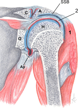
Fig. 13.2
Anatomy of the glenohumeral joint, coronal view. In light blue the articular cartilage and in red the synovial membrane covering the internal surface of the capsule. A acromion process, Ap axillary pouch, C clavicle, G glenoid cavity, H humeral head, SSB subacromial-subdeltoid bursa. 1 deltoid muscle, 2 tendon of the supraspinatus muscle
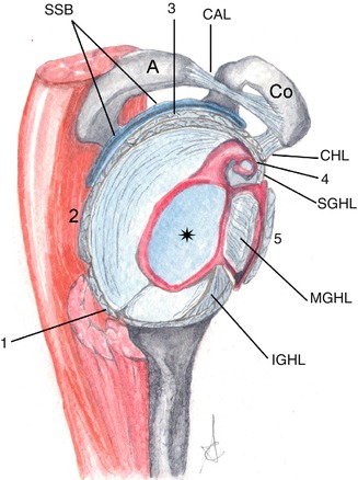
Fig. 13.3
Anatomy of the glenohumeral joint, sagittal view. The star shows the glenoid cavity covered by the articular cartilage. In red, the synovial membrane covering the internal surface of the capsule. A acromion process, CAL coracoacromial ligament, CHL coracohumeral ligament, Co coracoid process, IGHL inferior glenohumeral ligament, SSB subacromial-subdeltoid bursa, SGHL superior glenohumeral ligament, MGHL middle glenohumeral ligament. 1 tendon of the teres minor muscle, 2: tendon of the infraspinatus muscle, 3 tendon of the supraspinatus muscle, 4 tendon of the long head of biceps, 5 tendon of the subscapularis muscle. The rotator cuff tendons are merged with the capsule
The capsular complex, for didactic purposes, may be divided into the anterior and posterior part. Anteriorly, from the outside to the inside, we find the capsule; the superior, middle and inferior glenohumeral ligament; the synovial membrane and the relevant recesses; the labrum (fibrocartilaginous capsular fold on the bone margin of the glenoid cavity); and the scapular periosteum, externally reinforced by the subscapularis tendon. Posteriorly we can see the capsule, labrum and scapular periosteum, stabilised by the muscles of the rotator cuff.
This joint physiologically contains 1–2 ml of synovial fluid and it communicates with the sheath of the long head of the biceps brachii and the subscapularis recess.
The capsule is posteriorly anchored to the base of the glenoid labrum, while anteriorly we can find three types of insertion: (1) at the base of the labrum; (2) on the scapular neck, less than 1 cm from the labrum; and (3) on the scapular neck, more than 1 cm from the scapular neck.
13.1.1.3 Muscles
Rotator Cuff
It is a group of muscles involved in the movement and stabilisation of the shoulder. In anteroposterior direction, it consists of the subscapularis, supraspinatus, infraspinatus and teres minor muscles, with scapular origin and humeral insertion. The subscapularis muscle originates from, and lies into, the subscapularis fossa, and it is inserted at the level of the lesser tuberosity of the humerus. The supraspinatus and infraspinatus muscles originate in the corresponding fossae, the teres minor muscle from the middle third of the scapular lateral margin; each of them has a dedicated insertion point on the greater tuberosity of the humerus.
Long Head of the Biceps Brachii
It originates from the supraglenoid tubercle of the glenoid cavity; it has an intra-articular course, parallel to the superior glenohumeral ligament; it later becomes extra-articular, enveloped in a dedicated synovial sheath, lying in the intratubercular sulcus of the humerus and stabilised by the coracohumeral ligaments, transverse ligament, subscapularis and pectoralis major tendons. The short head of the biceps originates at coracoid process.
13.1.1.4 Ligaments
Coracoacromial ligament, between the anterior part of the coracoid process and the tip of the acromion process, forming the corresponding coracoacromial functional arch.
Coracohumeral ligament, between the lateral base of the coracoid process and the greater and lesser tuberosity of the humerus.
Glenohumeral ligaments (superior, middle and inferior). In 30 % of cases the middle glenohumeral ligament does not exist. The inferior glenohumeral ligament, going from the inferior glenoid labrum to the anatomical neck of the humerus, consists of an anterior and a posterior stripe, delimiting the axillary pouch.
Conoid and trapezoid coracoclavicular ligaments, stabilising the acromioclavicular joint.
Do not forget the superior and inferior acromioclavicular ligaments.
13.1.1.5 Bursae
Subacromial-Subdeltoid Bursa (SSB)
Adjacent to the inferior surface of the acromion process, superficial to the rotator cuff.
It physiologically contains a small amount of fluid only.
Subcoracoid Bursa
Between the tendon of the subscapularis muscle, short head of the biceps brachii and the coracobrachialis muscle. It is separated from the subscapularis recess. It is not in relation with the joint but it may communicate with the SSB.
Infraspinatus Bursa
Between the infraspinatus tendon and the articular capsule. It may communicate with the articular space.
13.1.2 Normal Imaging Anatomy
13.1.2.1 Conventional Radiology
The standard shoulder radiograph includes anteroposterior (AP) (in neutral position, internal and external rotation) and axillary projections.
The AP projection allows to display the head of the humerus which overlaps the glenoid cavity; it enables an oblique view of the glenohumeral joint, which usually forms an anterior angle of approximately 40°. In extrarotation the greater tuberosity of the humerus is projected laterally; in intrarotation the lesser tuberosity of the humerus is medial and the greater tuberosity anterior (Fig. 13.4).
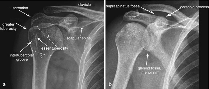
Fig. 13.4
Shoulder radiograph. Anteroposterior projection in extrarotation (a) and intrarotation (b). 1 anatomical neck, 2 surgical neck of the humerus
The glenohumeral space is not usually sufficiently visible in standard X-ray images; the lateral oblique projection, tangential to the glenohumeral joint, is therefore required (Grashey view): the patient lifts the non-examined side in supine decubitus, or he/she may simply rotate toward the affected side, in case of orthostasis. This projection allows to better display the real profile of the glenoid cavity and especially the glenohumeral space.
In axillary or superoinferior projection, in supine position and arm abducted not necessarily at 90° (optimal), incident beam angle of about 15–30° medially oriented, we obtain an axial view of the glenohumeral joint, particularly important in case of posterior dislocation of the head of the humerus (Fig. 13.5). Such a projection displays the effective relationship between the head of the humerus and the glenoid cavity.
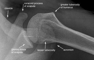
Fig. 13.5
Shoulder radiograph. Axillary or axial projection
The X-ray radiographs of the shoulder include a few more specific projections, and, namely:
Garth projection: for the examination of the superolateral part of the head of the humerus and the inferior glenohumeral joint. (It is useful in case of Bankart and Hill-Sachs lesions).
West Point projection (a variant of the axillary projection): allows the proper examination of the anteroinferior part of the glenoid cavity (useful in case of Bankart lesion).
Lawrence projection (variant of the axillary one): to highlight the same axillary structures visualised by the axillary projection.
Stryker notch projection: for the posterolateral examination of the head of the humerus (helpful in case of Hill-Sachs lesion).
Scapular outlet Y view or Neer projection: allows to better highlight the subacromial space and allows the lateral view of the scapula and oblique view of the proximal part of the humerus (Fig. 13.6).
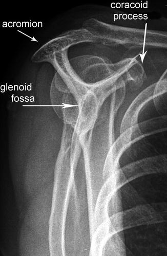
Fig. 13.6
Shoulder radiograph. Y projection
13.1.2.2 Ultrasound
It is the primary technique in case of lesion of the rotator cuff and in case of disorders of the long head of the biceps tendon. It requires good anatomical knowledge and clinical and semiotic information (Patte, Jobe, Gerber, Neer tests etc.). It is generally performed with linear probes with frequency between 7.5 and 10 Hz, allowing a panoramic view of the joint through the application of the following standard views:
Coronal view: in order to highlight from top to bottom the superficial hyperechoic stripe (cutaneous plane), thin hypoechoic layer (loose connective tissue strands forming the subcutaneous tissue), hyperechoic band (superficial aponeurotic fascia), tertiary fasciculi of the deltoid muscle, double hyperechoic band (SAB and adipose cleavage plane) and hyperechoic line (interface between the adipose cleavage plane and the adjacent rotator cuff). The rotator cuff, half-moon shaped, appears homogeneous, with medium echogenicity and thickness between 3.5 and 6.5 mm. From the posterior portions, toward the front, on the greater tuberosity of the humerus, we find the insertion of the tendons of the teres minor muscle, subspinatus and infraspinatus muscles. On the caudal margin of the rotator cuff, there is a hypoechoic band (articular cartilage) below which we find a hyperechoic half-moon line (cortex of the head of the humerus) (Fig. 13.7).
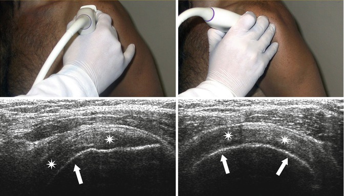
Fig. 13.7
Ultrasound scan of the supraspinatus tendon. The hyperechoic line (arrows) shows the humeral cortical bone and, immediately above, the supraspinatus muscle (stars)
Midsagittal line: it shows the course and longitudinal orientation of the tendons of the rotator cuff. Deeply to the subcutaneous adipose plane and the deltoid muscle, we find the hyperechoic SAB band, below which we find the insertion of the supraspinatus tendon.
Posterior sagittal line: it shows the muscular portion and the myotendinous junction of the subspinatus tendon up to the point of insertion on the greater tuberosity. The layers, from external to internal, have been widely described herein above; the superior portion consists of the subspinatus tendon while the inferior portion consists of the fibres of the teres minor muscle. Internally, we find a triangular hyperechoic structure representing the posterior glenoid labrum (Fig. 13.8).
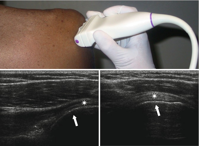
Fig. 13.8
Ultrasound scan of the infraspinatus tendon. The hyperechoic line (arrows) shows the humeral cortical bone and, immediately above, the infraspinatus muscle (stars)
Sagittal on the long head of the biceps: it allows to display the proximal insertion of the tendon into the glenoid cavity, its intra-articular and extra-articular course (Fig. 13.9a).

Fig. 13.9
Standard ultrasound scan of the long head of the biceps, arrowheads. (a) Sagittal view. (b) Axial view. The arrow is on the intertubercular or bicipital groove where the tendon travels
Anterior axial line: it shows the intertubercular groove of the head of the humerus (laterally delimited by the greater tuberosity and medially by the lesser tuberosity of the humerus); inside, we can see the hyperechoic oval image of the tendon of the long head of the humeral biceps; above it, we find a hyperechoic band going from the greater to the lesser tuberosity, showing the transverse ligament (Fig. 13.9b).
Anterior oblique line: it shows the insertion point of the tendon of the subscapularis muscle at the level of the humeral lesser tuberosity (Fig. 13.10).
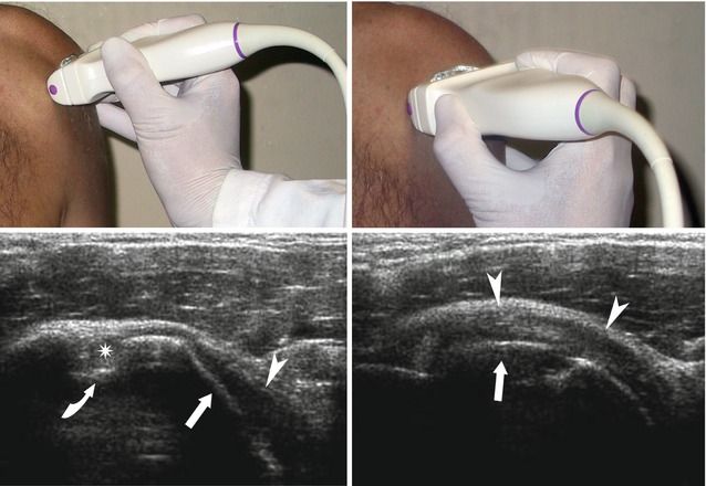
Fig. 13.10
Ultrasound scan of the subscapularis tendon with arm in extrarotation and intrarotation. The hyperechoic line (arrows) shows the humeral cortical bone and, immediately above, the subscapularis muscle (arrowheads). The curved arrow is on the bicipital groove where the long head of the biceps is located (star)
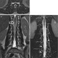
13.1.2.3 Computed Tomography
The multislice CT of the shoulder is usually performed with high spatial resolution, which is ideal for the subsequent three-dimensional (3D) reconstructions with different techniques, such as maximum-intensity projection (MIP), surfaces shaded display (SSD) and volume rendering (VR).
Axial scans with bone reconstruction algorithm, from the top, allow a good display of the acromioclavicular joint and the acromion process, the head of humerus with the glenoid cavity and the intertubercular groove containing the tendon of the humeral biceps muscle. MPR coronal reconstruction allows a perfect evaluation of the subacromial–subdeltoid area, while MPR sagittal reconstruction provides an anatomical view of the glenoid cavity and the acromion process (Fig. 13.11). With the soft tissues reconstruction algorithm, we can also study the tendons of the rotator cuff.
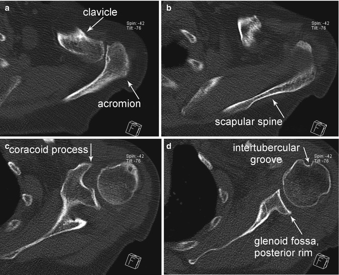
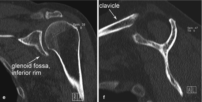
Fig. 13.11
Computed tomography axial projection (a–d), coronal (e) and sagittal (f) reconstruction
13.1.2.4 Magnetic Resonance Imaging
In MRI the patient is in supine position, arm along the trunk in partial external rotation, and T1- and T2-weighted sequences shall be acquired on the three spatial planes; further anatomical details may be obtained with arthro-MRI performed with intra-articular injection of 15–20 ml of paramagnetic contrast agent and T1-weighted sequences with fat suppression (Fig.13.12).
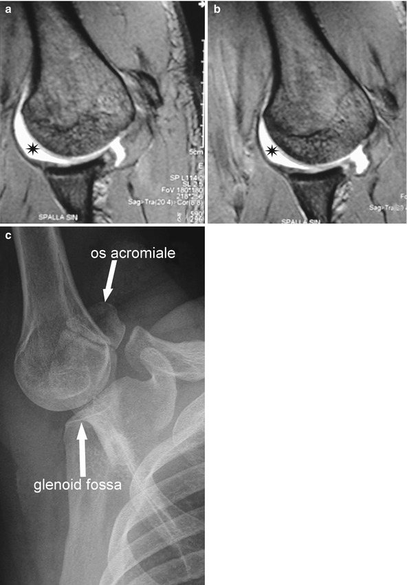
Fig. 13.12
MRI arthrogram. MRI images (a, b) obtained with abduction and extrarotation of the shoulder (ABER position) and the relevant X-ray projection (c). The contrast agent (star), hyperintense, is in the intracapsular space
Usually, under normal conditions, the tendons of the rotator cuff are hypointense in T1- and T2-weighted sequences, with or without suppression of the fat signal; the bone segments of the shoulder are hyperintense with a hypointense edge (cortical bone) in T1- and T2-weighted sequences, hypointense with hypointense fringe (cortical bone) in sequences with fat suppression: the glenoid labrum, triangular and fibrous extension of the glenoid margin has low signal similar to that of the meniscus of the knee, in T1- and T2-weighted sequences; there is only a small portion of fluid in the glenohumeral joint, hyperintense in T2-weighted sequences and hypointense in T1.
Coronal oblique sequences are oriented according to the axis of the tendon of the supraspinatus muscle, perpendicular to the glenohumeral joint, from the subscapularis muscle (anterior) to the infraspinatus muscle (posterior); the images show all the tendons of the rotator cuff: in particular, the subscapularis tendon anterior to the greater tuberosity of the humerus, the supraspinatus tendon, medial and, posteriorly, the infraspinatus (cranial) and teres minor tendons (caudal). Such a projection allows the study of the following structures: humeral epiphysis and diaphysis; tendon of the long head of the biceps, up to the insertion in the glenoid cavity, also visible along with the acromioclavicular joint and the deltoid; subscapularis; supraspinatus and infraspinatus; and teres minor muscles (Fig. 13.13).
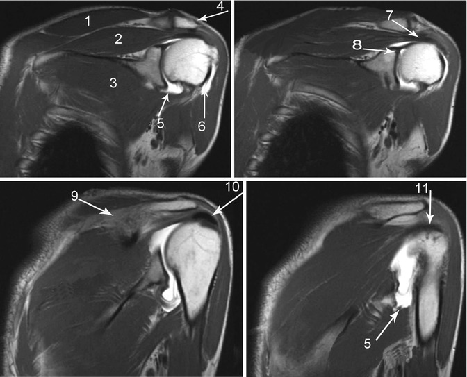
Fig. 13.13
Magnetic resonance. T1-weighted sequences, coronal view. The articular cavity is distended by contrast agent. 1 trapezius muscle, 2 supraspinatus muscle, 3 subscapularis muscle, 4 acromion, 5 axillary pouch, 6 biceps tendon, long head, 7 supraspinatus tendon, 8 origin of the biceps tendon, long head, 9 scapular spine, 10 calcium deposit, 11 infraspinatus tendon
The axial scans, perpendicular to the glenoid cavity, include the superior acromioclavicular joint up to the axillary area, allowing the examination of the intertubercular groove, the long head of the biceps brachii, the tendons of the rotator cuff and, in particular, of the infraspinatus (posterior) and subscapularis (anterior). It is also possible to perform an initial evaluation of the glenoid labia; however, a proper examination is not possible without intracapsular fluid, caused by effusion or injected as in MRI arthrogram. From top to bottom, we can also display the acromioclavicular joint and, just below, the coracoid process, the scapular spine and the deltoid muscle, along with the remaining muscles forming the rotator cuff (Fig. 13.14).
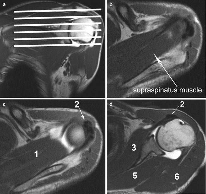
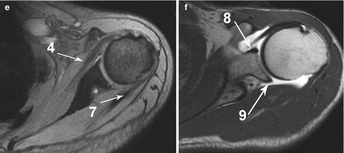
Fig. 13.14
Magnetic resonance. T1-weighted sequences, axial view. The articular cavity is distended by contrast medium. 1 supraspinatus muscle, 2 calcium deposits, 3 subscapularis muscle, 4 subscapularis tendon, 5 infraspinatus muscle, 6 deltoid muscle, 7 infraspinatus tendon, 8 anterior glenoid labrum, 9 posterior glenoid labrum
Oblique sagittal sequences, parallel to the glenoid surface, going from the scapular neck to the lateral margin of the greater tuberosity, are useful for the study of the acromioclavicular joint and, especially, for the assessment of the acromial shape and rotator cuff muscles when we need to understand size and location of possible lesions (Fig. 13.15).
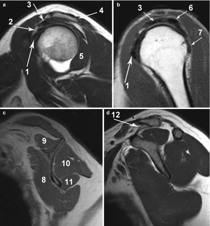
Fig. 13.15
Magnetic resonance. T1-weighted sequences, sagittal view. The articular cavity is distended by contrast medium. 1 subscapularis tendon, 2 biceps tendon, long head, 3 supraspinatus tendon, 4 acromion, 5 infraspinatus muscle, 6 infraspinatus tendon, 7 teres minor tendon, 8 subscapularis muscle, 9 supraspinatus muscle, 10 infraspinatus muscle, 11 teres minor muscle, 12 coracoclavicular ligament
13.2 Wrist
13.2.1 Normal Anatomy
The wrist is a particularly complex joint which consists of different joints (distal or inferior radioulnar, radiocarpal, midcarpal, intercarpal, pisotriquetral, carpometacarpal joints) supported by bones, tendons and ligaments (Fig. 13.16).
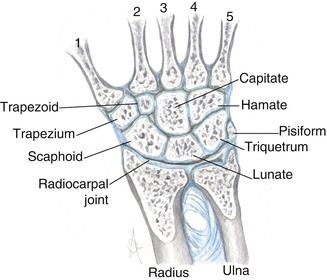
Fig. 13.16
Anatomy of the osseous structures of the wrist. Metacarpi (1, 2, 3, 4, and 5)
13.2.1.1 Bone Structures
Radius
It is a tubular bone covered with a thin cortical layer. The lateral far end is termed styloid process, on whose sides we find the two grooves for the extensor pollicis brevis and abductor pollicis longus (first extensor compartment).
The palm surface is slightly concave and contains the insertion of the radiocarpal tendons; the dorsal one, on the contrary, is convex and we find the tendons from the second to the fourth extensor compartments. The Lister’s tubercle is a bony prominence dividing the second and third tendon compartments.
The articular surface is also divided into the radial and ulnar parts by the interposition of another bony prominence: the first one has two fossae, respectively, for the articulation with the scaphoid and lunate bones; the second one, sigmoid or ulnar fossa, is round with the insertion of the radioulnar ligament on the dorsal and volar margins.
Ulna
It consists of a head, articulating with the radius, a prominence termed styloid and a central depression where the triangular fibrocartilage is inserted. Besides the radius, it articulates with the lunate and triquetrum. On the dorsal surface we find the sulcus for the sixth extensor tendon compartment.
At the level of the distal radioulnar joint, the length of the ulna and radium may vary: positive ulnar variance means that the ulna is longer; the opposite condition is termed negative ulnar variance. Normally, the ulnar variance is neutral.
Carpus
It consists of eight bones, organised in a proximal row (in lateromedial direction: scaphoid, lunate, triquetrum, pisiform bones) and a distal row (trapezium, trapezoid, capitate and hamate bones). The palm surface of the carpus is characterised by a cavity whose roof consists of the transverse ligament, called carpal tunnel; the medial, anterior and posterior borders are formed by the pisiform bone and hook of the hamate; the lateral, anterior and posterior ones, by the scaphoid and trapezium.
Metacarpus
It consists of five bones characterised by body, base and a far end called head, which articulates with the corresponding proximal phalanx. At the base of the metacarpi, we find the articular facets for the distal row of the carpus. They also touch each other at the base, through articular facets.
13.2.1.2 Joints and Triangular Fibrocartilage
There are six joints in the wrist (distal or inferior radioulnar, radiocarpal, midcarpal, intercarpal, pisotriquetral, carpometacarpal joints) with the first three ones being the main ones.
In 7 % of the people aged between 20 and 30, and in almost 50 % of the people aged between 60 and 70, there is a non-traumatic communication between the distal radioulnar and the radiocarpal joints. It is not uncommon also between the radiocarpal and the midcarpal ones. There is also a physiological and normal communication between the radiocarpal and the pisotriquetral joints.
Radioulnar Joint
It consists of the head of the ulna and the medial concavity of the radius, distally delimited by the triangular fibrocartilage; the triangular fibrocartilage complex (TFCC) has a stabilisation function and separates the radioulnar from the radiocarpal joint.
Radiocarpal Joint
It consists of the distal far end of the radius, triangular fibrocartilage and proximal carpal row of the carpus, separated from the mediocarpal joint by the intrinsic scapholunate and lunotriquetral ligaments.
Midcarpal Joint
Included between the bones of the two carpal rows, it communicates with the common carpometacarpal joint.
Triangular Fibrocartilage Complex
The TFCC consists of the articular disc, volar and dorsal radioulnar ligaments, collateral ulnar ligament and the sheath of the extensor carpi ulnaris; it has multiple points of insertion on the carpal bones (lunate, triquetrum and hamate) and it is supported by the ulnolunate and ulnotriquetral ligaments.
The disc is a robust fibrocartilage, similar to that of the menisci of the knee; it is inserted on the distal, ulnar margin of the radius, at the level of the sigmoid fossa and at the base of the ulnar styloid process.
13.2.1.3 Ligaments
The wrist ligaments are divided into intrinsic and extrinsic ligaments; the first ones have their origin and insertion on the carpal bones, and the second ones connect the radius or ulna to the carpal bones and these ones to the metacarpi.
Intrinsic Ligaments
They are divided into proximal (scapholunate and lunotriquetral) ligaments, separating the radiocarpal compartment from the metacarpal one, and distal (trapeziotrapezoid, trapezio-capitate and capitohamate) ligaments, enabling the physiological communication between the midcarpal and the carpometacarpal compartments.
The carpometacarpal ligaments are distal intrinsic: pisometacarpal, carpometacarpal of the thumb, dorsal and volar carpometacarpal ligaments.
Extrinsic Ligaments
The extrinsic ligaments are the:
Volar radiocarpal ligaments (radioscaphocapitate, long radiolunate ligament also referred to as radiolunotriquetral, short radiolunate and radioscapholunate ligaments, also referred to as ligament of Testut). The arched ligament, or fifth ligament, is actually a confluence of ligaments on volar capitate including radioscaphocapitate, ulnocapitate and triquetrocapitate ligaments.
Dorsal radiocarpal ligament, also referred to as radiolunotriquetral.
Volar midcarpal ligament (scaphotrapezium-trapezoid, scaphocapitate, triquetrocapitate, triquetrohamate, pisohamate and deltoid ligaments).
Dorsal midcarpal ligaments (intercarpal, scaphotriquetral ligaments).
The group includes also the ulnolunate, ulnotriquetral and ulnocapitate ligaments.
13.2.1.4 Tendons and Muscles
We can distinguish two parts: the dorsal fascia, where we find the tendons of the extensor muscles, and the volar one, where we find the tendons of the flexor muscles (Figs. 13.17, and 13.18).
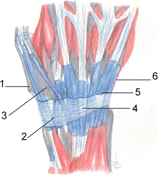
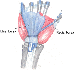
Fig. 13.17
Anatomy of the wrist, dorsal face. The numbers show the compartments of the extensor tendons. Compartment 1 abductor pollicis longus and extensor pollicis brevis, 2 extensor carpi radialis longus and brevis, 3 extensor pollicis longus, 4 extensor indicis, extensor digitorum, 5 extensor digiti minimi (ex digiti quinti proprius), 6 extensor carpi ulnaris
Fig. 13.18
Anatomy of the wrist, volar face. Radial and ulnar bursae, along with the sheath of the flexor pollicis lungus and sheath of the common flexors digitorum (2^, 3^, 4^ and 5^ digits)
Extensor Tendons
Extensor tendons of the forearm muscles are stabilised by the retinaculum which, through deep insertions, divides such a space into the following six compartments, two of them lateral and in radioulnar direction and the other ones medial to the Lister’s tubercle:
I.
Abductor pollicis longus and extensor pollicis brevis
II.
Extensor carpi radialis longus and extensor carpi radialis brevis
III.
Extensor pollicis longus
IV.
Extensor digitorum (communis) and separated extensor indicis (proprius)
V.
Extensor digiti minimi (for the fifth finger)
VI.
Extensor carpi ulnaris
Flexor Tendons
The flexor retinaculum, called transverse ligament, is located in the volar fascia and inserted medially on the pisiform bone and on the hook process of the hamate, laterally on the scaphoid tuberosity and trapezium palmar surface; it is connected above to the volar ligament and below, to the volar aponeurosis; it is extended between the two far ends of the carpal concavity, forming the carpal tunnel. The flexor tendons in this region are:
Flexor pollicis longus: completely covered with a synovial sheath, it communicates with the radial bursa of the carpus; it lies in the tunnel, dorsal to the median nerve, and it is inserted on the distal phalanx of the finger.
Flexor digitorum profundus and superficialis: inside the carpal tunnel, dorsal and medial to the median nerve covered by the ulnar bursa up to the base of the metacarpi. The ulnar bursa (common flexor tendon sheath) continues distally and covers the tendons of the fifth finger, while those for the second, third and fourth fingers are enveloped in their own synovial sheath.
The flexor carpi radialis is external to the carpal tunnel, separated from the above-mentioned flexor tendons by the deep lamina of the retinaculum; it is inserted at the base of the second metacarpus. The flexor carpi ulnaris is inserted on the pisiform bone. The tendon of the long volar muscle lies external to the flexor retinaculum.
13.2.1.5 Neurovascular System
Tendons, vessels and nerves of the wrist are organised in two canals.
Carpal Tunnel
Fibro-osseous canal bordered by carpals (dorsal), scaphoid and trapezium tubercles (lateral), hook of hamate and pisiform (medal) and closed by the flexor retinaculum.
Several structures pass in this tunnel, such as the median nerve, the flexor pollicis longus tendons and superficial and deep tendons of the fingers, with their relevant synovial sheathes.
Ulnar Guyon’s Canal
Fibrous-osseous triangular canal containing fat and the ulnar artery, vein and nerve.
It is located in the anteromedial part of the wrist, bordered by the pisiform and pisohamate ligament (medial), hook of the hamate (distal), flexor retinaculum (dorsal) and volar carpal ligament (volar).
13.2.1.6 Synovial Bursae
There are several synovial bursae in the wrist, most of them are virtual spaces, not visible unless stretched by fluid; the main ones are the radial and ulnar bursae. The first one is located on the radial side of the palm; it is an expansion of the sheath of the tendon of the flexor pollicis longus; the second one originates on the medial-volar part of the wrist and it communicates with the sheath of the flexor of the fifth finger.
13.2.2 Normal Imaging Anatomy
13.2.2.1 Conventional Radiology
The wrist radiograph is usually performed in anteroposterior (AP) and latero-lateral (LL) projection. Both of them must be acquired in neutral position, without any ulnar or radial deviation on the frontal plane, without flexion or extension on the sagittal plane or without pronation and supination on the coronal plane of the wrist.
In the AP view neutral prono-supination and flexo-extension are obtained when the hand lies flat on the volar surface, with the elbow flexed at 90°, forearm on the horizontal plane and shoulder abducted at 90° from the trunk. If the long axis of the third metacarpal, capitate and the radius fall in a straight line, there is not radial or ulnar deviation. In AP projections the distal portion of radius and ulna is well displayed, along with the carpal bones and the metacarpal base. In this way, the thumb is displayed oblique; the bases from the second to the fifth metacarpi partially overlap each other; also trapezium and trapezoid and triquetrum and pisiform bones overlap each other.
Lateral view has to be performed in orthogonal position compared to AP projection in order to obtain the overlapping of the radius and ulna. The arm is vertical, with a 90° flexion of the forearm on the table (Fig. 13.19). In such a projection the distal portions of the radius and ulna overlap each other, allowing the study of the normal articular relationships between the radius, lunate and capitate bone, through the correct alignment of the longitudinal axis. The thumb is displayed in dorso-volar direction.
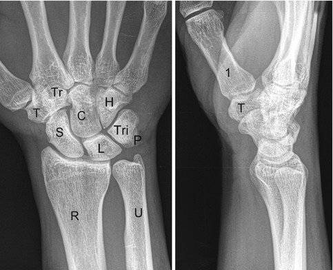
Fig. 13.19
Wrist X-ray in AP and LL projection. Radius (R), ulna (U), scaphoid (S), lunate (L), triquetrum (Tri), pisiform (P), trapezium (T), trapezoid (Tr), capitate (C), hamate (H), first metacarpal (1)
In specific clinical conditions, the X-ray can be integrated with other, properly targeted, X-radiographs.
The oblique projections (in semipronation and semisupination) are performed starting from the lateral projection followed by, respectively, a pronation and a supination of 45°. Oblique view in semipronation enables the study of scaphoid, trapezium, trapezoid bones and the trapeziometacarpal joint; oblique X-ray in semisupination enables the study of the triquetral and pisiform and the pisotriquetral joint (Fig. 13.20).
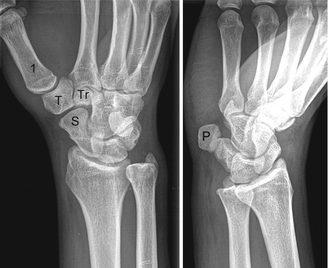
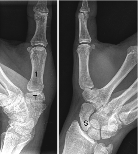
Fig. 13.20
Wrist X-ray in semi-pronation and semi-supination projections. First metcarpal (1), pisiform (P), scaphoid (S), trapezium (T), trapezoid (Tr)
Other specific projections are available for the study of first carpometacarpal joint (or Kapandji’s axial oblique view), the scaphoid bone, the carpal tunnel (Gaynor-Hart method) and the scapholunate space (Fig. 13.21).