Lower Limb III: Ankle and Foot


Lower Limb III: Ankle and Foot


Ankle and Foot

The ankle is the most frequently injured of all the major weight-bearing joints in the body. Most victims are young adults injured while participating in athletic activities such as running, skiing, and soccer. Ankle structures susceptible to injury include bones, ligaments, tendons, and syndesmoses; ligaments can be damaged in the absence of fractures. When this occurs, damage to ligaments may go unrecognized on conventional radiographs, with the result that the patient is not properly treated.

The type of fracture usually indicates the mechanism of injury determined, as Kleiger has pointed out, by the position of the foot, the direction and intensity of the applied force, and the resistance of the structures making up the joint. The mechanism of injury may in turn serve as an indicator of which ligament structures are damaged.

Although occasionally meticulous history taking and clinical examination can help determine the mechanism of trauma and predict damage to the various structures, radiologic examination is the key to reliable evaluation of the site and extent of injury. There are two basic types of ankle trauma: inversion injuries and eversion injuries. These, however, may be complicated by internal or external rotation, hyperflexion or hyperextension, and vertical compression forces.

Foot injuries are also common and usually result from direct trauma, such as a blow or a fall from a height; only rarely do such injuries result from indirect forces such as abnormal stress or strain of muscles or tendons. Foot fractures, accounting for 10% of all fractures, are more common than dislocations, which usually are associated with fractures, and occur at the midtarsal, tarsometatarsal, and metatarsophalangeal articulations.


Anatomic-Radiologic Considerations

The ankle joint proper consists of the tibiotalar and distal tibiofibular articulations, the latter a syndesmotic joint rather than a true synarthrodial one. In matters of injury, however, one must consider that the ankle joint acts as a unit with other joints of the foot, particularly the talocalcaneal (subtalar) articulation, where application of stress can have great impact on ankle injuries.

The ankle joint is formed by three bones—the distal tibia and fibula and the talus—and three principal sets of ligaments—the medial collateral (deltoid) ligament; the lateral collateral ligament, consisting of the anterior talofibular, posterior talofibular, and calcaneofibular ligaments; and the syndesmotic complex, a fibrous joint between the distal tibia and the fibula (Fig. 10.1). The distal tibiofibular syndesmotic complex, one of the most important anatomic structures in maintaining ankle integrity and stability, consists of three elements: the distal anterior tibiofibular ligament, the distal posterior tibiofibular ligament, and the interosseous membrane.

From the viewpoint of anatomy and kinetics, the foot is divided into three distinct sections: hindfoot, midfoot, and forefoot. The hindfoot, separated from the midfoot by the midtarsal (or Chopart) joint, includes the talus and calcaneus; the midfoot, separated from the forefoot by the tarsometatarsal (Lisfranc) joint, includes the navicular, cuboid, and three cuneiform bones; and the forefoot includes the metatarsals and phalanges (Fig. 10.2). The muscles attached to the tibia and fibula end in tendons proximal to or at the level of the ankle joint. These tendons insert into the foot (Fig. 10.3).

A word about terminology is in order because the terminology describing motion of the ankle and foot in the literature is not uniform and confusion has been created about the various mechanisms of ankle and foot injuries. Frequently, but incorrectly, the terms adduction, inversion, varus, and supination have been used interchangeably, as have their counterparts abduction, eversion, valgus, and pronation. However, supination and pronation are more appropriately applied to compound motion. Supination consists of adduction and inversion of the forefoot (motion in the tarsometatarsal and midtarsal joints) and inversion of the heel, which assumes a varus configuration (motion in subtalar joint), as well as slight plantar flexion of the ankle (tibiotalar) joint. In pronation, compound motion consists of abduction and eversion of the forefoot (motion in the tarsometatarsal and midtarsal joints) and eversion of the heel, which assumes a valgus configuration (motion in the subtalar joint), together with slight dorsiflexion (or dorsal extension) of the ankle (Fig. 10.4).

Adduction properly applies to medial deviation of the forefoot, and abduction to lateral deviation of the forefoot, both motions occurring in the tarsometatarsal (Lisfranc) joint; adduction of the heel refers to inversion of the calcaneus; and abduction of the heel refers to eversion of the calcaneus, both motions occurring in the subtalar joint. Plantar flexion refers to caudad (downward) foot motion, dorsiflexion to cephalad (upward) foot motion— motions occurring in the ankle (tibiotalar) joint. Varus and valgus should not be used to describe motion but should be reserved for the description of ankle or foot position in case of deformity. Occasionally, varus and valgus are used interchangeably with inversion and eversion to describe the applied stress.


Imaging of the Ankle and Foot


Ankle

The standard radiographic examination of the ankle, as a rule, includes the anteroposterior (including the mortise), lateral, and oblique projections. Stress views are also frequently obtained for evaluating ankle injuries. These may also need to be supplemented with special projections.


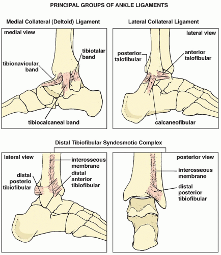
FIGURE 10.1 Ligaments of the ankle. Three principal sets of ligaments form the ankle joint: the medial collateral (deltoid) ligament, the lateral collateral ligament, and the distal tibiofibular syndesmotic complex, which is important for maintaining ankle integrity and stability.


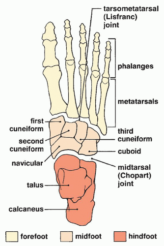
FIGURE 10.2 Anatomic divisions of the foot. The foot can be viewed as comprising three anatomic parts: the hindfoot, midfoot, and forefoot, separated respectively by the midtarsal (Chopart) and tarsometatarsal (Lisfranc) joints.


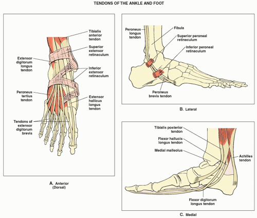
FIGURE 10.3 Tendons of the ankle and foot. The attachment of various tendons of the ankle and foot are depicted, as viewed from the dorsal aspect (A), lateral aspect (B), and medial aspect (C).

On the anteroposterior view, the distal tibia and fibula, including the medial and lateral malleoli, are well demonstrated (Fig. 10.5). On this projection, it is important to note that the fibular (lateral) malleolus is longer than the tibial (medial) malleolus. This anatomic feature, important for maintaining ankle stability, is crucial for reconstruction of the fractured ankle joint. Even minimal displacement or shortening of the lateral malleolus allows lateral talar shift to occur and may cause incongruity in the ankle joint, possibly leading to posttraumatic arthritis. A variant of the anteroposterior projection, in which the ankle is internally rotated 10 degrees, is called the mortise view because the ankle mortise is well demonstrated on it (Fig. 10.6).

The lateral view is used to evaluate the anterior aspect of the distal tibia and the posterior lip of this bone (the so-called third malleolus) (Fig. 10.7). Some fractures oriented in the coronal plane can be better visualized on this projection. Ankle joint effusion can also be assessed on this view (see Fig. 10.65).

The oblique view of the ankle, best obtained with the foot internally rotated approximately 30 to 35 degrees, is effective in demonstrating the tibiofibular syndesmosis and the talofibular joint (Fig. 10.8). An external oblique view may also be required to evaluate the lateral malleolus and the anterior tibial tubercle (Fig. 10.9).

Most ankle ligament injuries require stress radiography, ankle joint arthrography, computed tomography (CT), or magnetic resonance imaging (MRI) (see later) for demonstration and sufficient evaluation. Some, however, can be deduced from the site and extension of fractures on the standard radiographic examination. A thorough knowledge of the skeletal and soft-tissue topographic anatomy of the ankle, together with an understanding of the kinematics and mechanism of ankle injuries, will aid the radiologist in correctly diagnosing traumatic conditions and predicting ligament injuries. With such understanding, the radiologist can even determine the sequence of injury to the various structures.

Some ligament injuries may be diagnosed on the basis of disruption of the ankle mortise and displacement of the talus; others can be deduced from the appearance of fractured bones. For example, fibular fracture above the level of the ankle joint indicates that the distal anterior tibiofibular ligament is torn. Fracture of the fibula above its anterior tubercle strongly suggests that the tibiofibular syndesmosis is completely disrupted. Fracture of the fibula above the level of the ankle joint without accompanying fracture of the medial malleolus indicates rupture of the deltoid ligament. Transverse fracture of the medial malleolus indicates that the deltoid ligament is intact. High fracture of the fibula associated with a fracture of the medial malleolus or tear of the tibiofibular ligament, the


so-called Maisonneuve fracture (see later), indicates rupture of the interosseous membrane up to the level of the fibular fracture.


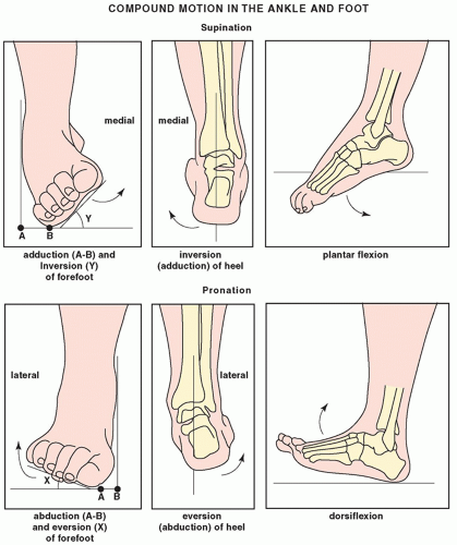
FIGURE 10.4 Motion in the ankle and foot. Supination is a compound motion consisting of adduction and inversion of the forefoot, together with inversion of the heel and slight plantar flexion in the ankle joint. In pronation, the compound motion involves abduction and eversion of the forefoot with eversion of the heel and slight dorsiflexion in the ankle joint.


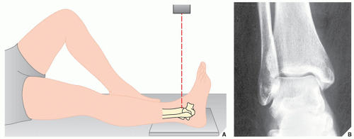
FIGURE 10.5 Anteroposterior view. (A) For the anteroposterior view of the ankle, the patient is supine on the radiographic table with the heel resting on the film cassette. The foot is in neutral position, with the sole perpendicular to the leg and the cassette. The central beam (red broken line) is directed vertically to the ankle joint at the midpoint between both malleoli. (B) The radiograph in this projection demonstrates the distal tibia, particularly the medial malleolus, the body of the talus, and the tibiotalar joint. Note, however, the overlap of the distal fibula and the lateral aspect of the tibia. The tibiofibular syndesmosis is not clearly demonstrated.


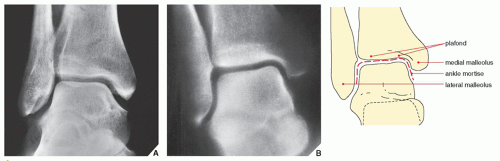
FIGURE 10.6 Mortise view. (A) The mortise view, a variant of the anteroposterior projection obtained with 10-degree internal rotation of the ankle, eliminates the overlap of the medial aspect of the distal fibula and the lateral aspect of the talus, so the space between these bones is well demonstrated. (B) The ankle mortise, shown here on a tomographic cut through the ankle joint, is formed by the medial malleolus, the articular surface of the distal tibia (the ceiling or plafond), and the lateral malleolus; it is shaped like an inverted U.


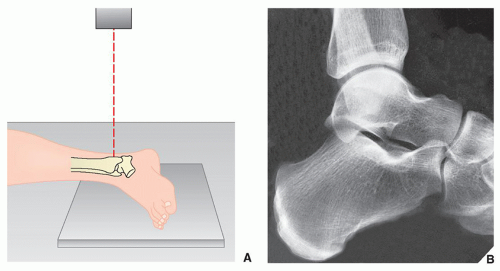
FIGURE 10.7 Lateral view. (A) For the lateral projection of the ankle, the patient is placed on his or her side with the fibula resting on the film cassette and the foot in the neutral position. The central beam is directed vertically to the medial malleolus. (The lateral view can also be obtained by placing the medial side of the ankle against the cassette.) (B) On the radiograph obtained in this projection, the distal tibia, talus, and calcaneus are seen in profile, and the fibula overlaps the posterior aspect of the tibia and the posterior aspect of the talus. The tibiotalar and subtalar joints are well demonstrated. Note the posterior lip of the tibia, also known as the third malleolus.


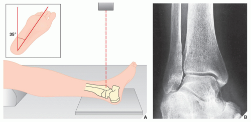
FIGURE 10.8 Internal oblique view. (A) For the internal oblique view of the ankle, the patient is supine, and the leg and foot are rotated medially approximately 35 degrees (inset). The foot is in the neutral position, forming a 90-degree angle with the distal leg. The central beam is directed perpendicular to the lateral malleolus. (B) On the radiograph, the medial and lateral malleoli, the tibial plafond, the dome of the talus, the tibiotalar joint, and the tibiofibular syndesmosis are well demonstrated.


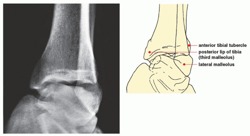
FIGURE 10.9 External oblique view. On the external oblique view, for which the patient is positioned as for the internal oblique view but with the limb rotated laterally approximately 40 to 45 degrees, the lateral malleolus and the anterior tibial tubercle are well demonstrated.

When radiographs of the ankle are normal, however, stress views are extremely important in evaluating ligament injuries (see Fig. 4.5). Inversion (adduction) and anterior-draw stress films are most frequently obtained; only rarely is an eversion (abduction)-stress examination required.

On the inversion-stress film, obtained in the anteroposterior projection, the degree of talar tilt can be measured by the angle formed by lines drawn along the tibial plafond and the dome of the talus (Fig. 10.10). This angle helps diagnose tears of the lateral collateral ligament. However, the wide range of normal values for these measurements may make interpretation difficult, and thus comparison studies of the contralateral ankle should be obtained. Even this method is not always accurate; up to 25 degrees of talar tilt has been reported in people with no history of injury, and occasionally, there will be a patient whose ankles exhibit considerable variation in measurement. Many authorities advise that with forced inversion, tilt less than 5 degrees is normal,
5 to 15 degrees may be normal or abnormal, 15 to 25 degrees strongly suggests ligament injury, and more than 25 degrees is always abnormal. With forced eversion, talar tilting of more than 10 degrees is probably pathologic.


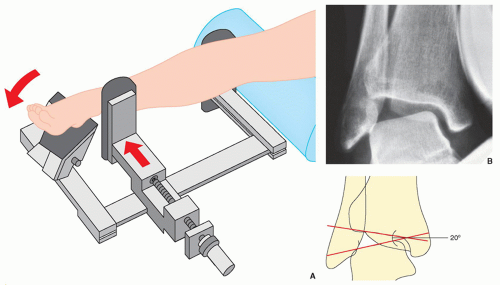
FIGURE 10.10 Inversion stress view. (A) For inversion (adduction)-stress examination of the ankle, the foot is fixed in the device while the patient is supine. The pressure plate, positioned approximately 2 cm above the ankle joint, applies varus stress (red arrows) adducting the heel. (If the examination is painful, 5 to 10 mL of 1% lidocaine or a similar local anesthetic is injected at the site of maximum pain.) (B) On the anteroposterior radiograph, the degree of talar tilt is measured by the angle formed by lines drawn along the tibial plafond and the dome of the talus. The contralateral ankle is subjected to the same procedure for comparison.


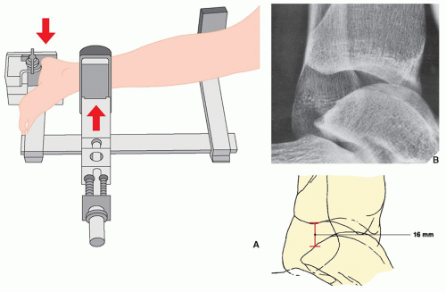
FIGURE 10.11 Anterior-draw stress view. (A) For anterior-draw stress examination, the patient is placed on his or her side, with the foot in the device. The pressure plate, positioned anteriorly approximately 2 cm above the ankle, applies posterior stress (red arrows) on the heel. During the examination, the amount of pressure is monitored on a light-emitting diode digital reader. (B) On the lateral stress film, the amount of transposition of the talus in relation to the distal tibia can be determined.

The anterior-draw stress film, obtained in the lateral projection, provides a useful measurement for determining injury to the anterior talofibular ligament (Fig. 10.11). Values of up to 5 mm of separation between the talus and the distal tibia are considered normal; values between 5 and 10 mm may be normal or abnormal, and the opposite ankle should be stressed for comparison. Values above 10 mm always indicate abnormality.

Ancillary imaging techniques are essential to the diagnosis and evaluation of many ankle injuries. CT may be required to determine the position of comminuted fragments in complex fractures, for example, of the distal tibia, talus, and calcaneus. Arthrography (Fig. 10.12) is occasionally used for assessing the integrity of the ligamentous structures in acute trauma, although recently, it has been almost completely supplanted by MRI. It is still, however, an effective technique for evaluating the articular cartilage and detecting and localizing loose osteocartilaginous bodies. It is also helpful in evaluation of chondral and osteochondral fractures and osteochondritis dissecans, which usually affects the dome of the talus. A singlecontrast study is usually performed to assess the integrity of the ankle ligaments. For evaluating the articular cartilage, a double-contrast study (combining a positive contrast agent and air) is more effective.

Ankle tenography is a useful procedure for evaluating tendon tears, particularly tears of the Achilles tendon, peroneus longus and brevis, tibialis posterior, flexor digitorum longus, and flexor hallucis longus. According to Bleichrodt and colleagues, tenography particularly has proved to be reliable in the diagnosis of injuries of the calcaneofibular ligament, with a sensitivity of 88% and specificity of 87% to 94%. In a procedure similar to that for ankle arthrography, a 22-gauge needle is inserted into the tendon sheath, with the needle tip directed distally, and 15 to 20 mL of contrast medium is injected under fluoroscopic guidance. Radiographs are then obtained in the standard projections (Fig. 10.13). Tear is indicated by the extravasation of contrast agent from the tendon sheath, abrupt termination of the contrast-filled tendon sheath, or leak of contrast into the adjoining articulations (see Figs. 10.68, 10.69, and 10.70). Recently, this technique has been completely replaced by MRI (see Fig. 10.71).

CT is an effective modality to evaluate various ligaments and tendons because the soft-tissue contrast resolution of CT allows the easy differentiation of these structures from surrounding fat. Specifically, tendon injuries including tendinitis, tenosynovitis, and rupture and dislocation of tendons can be effectively diagnosed. The major limitation in evaluating pathologic conditions of tendons with CT is the inability to scan the tendons in the coronal and sagittal planes. Reformation images, while occasionally helpful, suffer from the lack of spatial resolution and require additional examination time.

For adequate CT of the ankle and foot, proper positioning of the leg in the gantry is essential. In addition, because nomenclature for imaging planes of the feet occasionally creates a problem, it is important to recognize that the coronal, sagittal, and axial planes of the ankle and foot are determined the same way as for the body (Fig. 10.14A). For coronal images, the knees are flexed and the feet are positioned flat against the gantry table. The coronal sections are obtained with the beam directed to the dorsum of the foot. More commonly modified coronal images are obtained by angling the gantry or by using a foot wedge (Fig. 10.14B). A lateral scanogram helps to establish the degree of necessary gantry tilt. Axial images are obtained with the feet perpendicular to the gantry table, great toes together, and the knees fully extended. The beam is directed parallel to the soles of the feet. Sagittal images are usually generated by using reformation technique, although direct sagittal sections can also be obtained by placing the patient in the lateral decubitus position. Images in all planes are usually acquired using 3- or 5-mm thin contiguous sections. For threedimensional (3D) reconstruction, 1.5- or 2-mm contiguous sections are required, although 5-mm sections with a 3-mm overlap can also be used.

MRI, with its direct multiplanar capabilities and excellent soft-tissue contrast resolution, has proved to be superior to CT for the evaluation of ankle tendons and ligaments. The tendons show uniformly low signal intensity in all spin echo pulse sequences, with the exception of the Achilles tendon and tibialis posterior tendon. These two tendons, on long repetition time (TR) sequences, occasionally show small foci of intermediate signal intensity within their substance, particularly near their insertions to the calcaneal tuberosity and the navicular bone, respectively. From a practical point of view, it is helpful to memorize the location and relationship


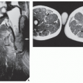
of various tendons seen on axial MR image of the ankle by using the mnemonic phrase, “Tom, Dick, and Harry” for the posteromedial aspect, and “TED” for the anterolateral aspect of the ankle (Fig. 10.15). The ankle ligaments, likewise, demonstrate low signal intensity on MR images, with the exception of the posterior talofibular ligaments, which often appears inhomogeneous, similar to the anterior cruciate ligament of the knee. The anterior and posterior talofibular ligaments can be visualized over their entire length on axial scans with the foot in neutral position (Fig. 10.16) because they are approximately in the same plane of section. The calcaneofibular ligament can be similarly visualized when the foot is in 40-degree plantar flexion. The anterior and posterior tibiofibular ligaments can be demonstrated on the axial images in more proximal sections (Fig. 10.17).


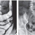
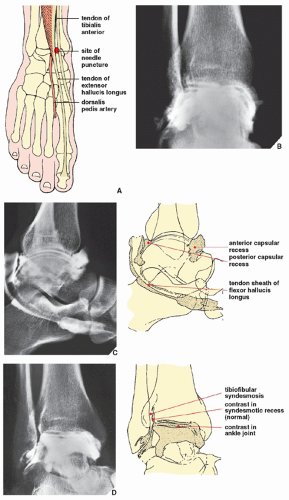
FIGURE 10.12 Arthrography of the ankle joint. (A) For arthrographic examination of the ankle, the patient is supine on the table, with the foot in the neutral position (see Fig. 10.5A). Under fluoroscopic control, the injection site between the tendons of the tibialis anterior and the extensor hallucis longus is marked. Care should be taken to avoid puncturing the dorsalis pedis artery, which should be located by palpation and its site marked on the skin. The needle (preferably 21-gauge) is directed slightly cephalad to avoid the overhanging anterior margin of the tibia. After the joint is entered, approximately 5 to 7 mL of 60% meglumine diatrizoate or a similar contrast agent is injected for a single-contrast arthrogram. For a double-contrast study, 1 to 2 mL of positive contrast agent and 6 to 8 mL of room air are injected. Films are then obtained in the standard anteroposterior, lateral, and oblique projections. (B) The normal anteroposterior radiograph shows contrast agent outlining the ankle joint, coating the articular surface of the talus and extending into the syndesmotic recess, which normally should not exceed 2.5 cm. (C) On the lateral radiograph, the anterior and posterior capsular recesses are outlined. Filling of the posterior facet of the subtalar joint represents a normal variant, occurring in approximately 10% of cases (see Fig. 10.69C). In approximately 20% of cases, the tendon sheaths of the flexor hallucis longus and flexor digitorum longus opacify on the medial aspect of the ankle. When this occurs, the full extension of the flexor hallucis longus should be noted as it passes proximal to the groove in the talar tubercle and into the groove beneath the sustentaculum tali. Under normal conditions, no tendon sheath opacification should occur on the lateral side of the ankle. (D) Oblique radiograph demonstrates the tibiofibular syndesmosis. No contrast agent should be seen in this area except for normal opacification of the syndesmotic recess.


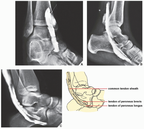
FIGURE 10.13 Ankle tenography. Tenograms in the oblique (A) and lateral (B) projections demonstrate the normal appearance of the tendon of the flexor hallucis longus. On the oblique radiograph, note the distal direction of the needle tip at the beginning of the injection. Normally, the tendon of the flexor hallucis longus does not opacify beyond the limit of the Lisfranc joint. (C) On the normal tenogram of the peroneus longus and brevis, seen here on the lateral radiograph, note the position of these tendons below the flexor hallucis longus. The tendon of the peroneus brevis is seen normally opacified; the tendon of the peroneus longus passes below it, crossing into the plantar aspect of the foot to its insertion at the base of the first metatarsal bone.


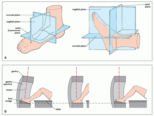
FIGURE 10.14 Anatomic and imaging planes. (A) Anatomic planes of the ankle and foot and (B) CT imaging planes. (B, Modified from Berquist TH, ed. Radiology of the foot and ankle. New York: Raven Press; 1989.)


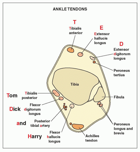
FIGURE 10.15 Schematic representation of ankle tendons on axial MRI. (Modified from Helms CA, Major NM, Anderson MW, et al. Musculoskeletal MRI, 2nd ed. Philadelphia: Saunders/Elsevier; 2009:384-429.)


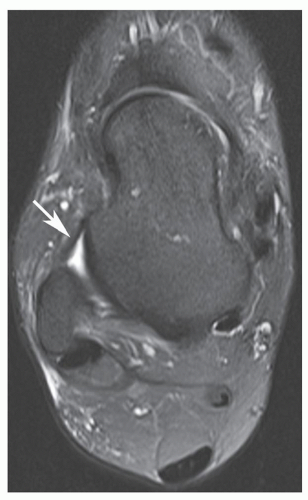
FIGURE 10.16 MRI of the anterior talofibular ligament. Axial T2-weighted MR image through the lateral malleolus and talus demonstrates normal anterior talofibular ligament (arrow).


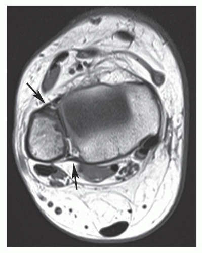
FIGURE 10.17 MRI of the anterior and posterior tibiofibular ligaments. Axial T1-weighted MR image shows normal anterior and posterior tibiofibular ligaments (arrows).

On the sections in the sagittal plane, the tibialis posterior, flexor digitorum longus, and flexor hallucis longus tendons are identified on the medial cuts. The peroneus longus and brevis tendons are seen on the lateral sections (Fig. 10.18). The Achilles tendon is best seen on midline sagittal
section (Fig. 10.19). The coronal plane is also effective in the visualization of various ligaments and tendons (Fig. 10.20).


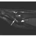
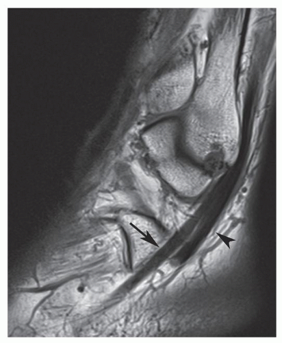
FIGURE 10.18 MRI of the peroneus longus tendon. Sagittal T1-weighted MR image through lateral malleolus shows normal appearance of peroneus brevis (arrow) and longus (arrowhead) tendons as they curve around the lateral malleolus.


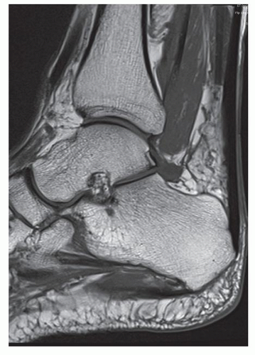
FIGURE 10.19 MRI of the Achilles tendon. Midline sagittal T1-weighted MR image demonstrates normal Achilles tendon. Note the uniformly low signal intensity of the tendon contrasting with the high signal intensity of the anterior fat pad.

The pathologic conditions of tendons and ligaments are demonstrated by discontinuity of the anatomic structure, the presence of high signal intensity within the tendon substance on T2-weighted images, and inflammatory changes within or around the tendons, which again can be demonstrated by a change in the normal signal intensity.


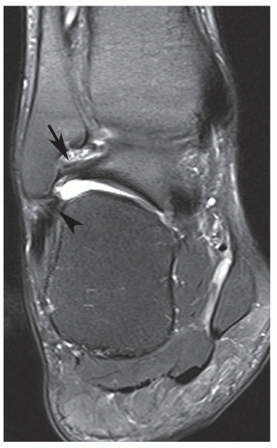
FIGURE 10.20 MRI of the posterior talofibular and calcaneofibular ligaments. Coronal T2-weighted MR image of the ankle shows normal posterior talofibular (arrow) and calcaneofibular (arrowhead) ligaments.


Foot

Most injuries to the foot can be sufficiently evaluated on the standard radiographic examination of the foot, which includes the anteroposterior, lateral, and oblique projections. Only occasionally are special tangential projections required.

The anteroposterior radiograph of the foot adequately demonstrates the metatarsal bones and phalanges (Fig. 10.21) This view reveals an important anatomic feature known as the first intermetatarsal angle, which normally ranges from 5 to 10 degrees (Fig. 10.21C). This angle is an important factor in the evaluation of forefoot deformities because it represents a way to quantify the amount of metatarsus primus varus associated with hallux valgus. On the lateral radiograph (Fig. 10.22A,B), Boehler angle (also known as a tuber angle), an important anatomic relation of the talus and the calcaneus, can be appreciated (Fig. 10.22C). In fractures of the calcaneus, this angle, which normally ranges from 20 to 40 degrees, is decreased because of compression of the superior aspect of the bone (see Fig. 10.81). This measurement also aids in the evaluation of depression of the posterior facet of the subtalar joint. On the lateral view, calcaneal pitch can also be evaluated. This measurement is an indication of the height of the foot and normally ranges from 20 to 30 degrees (Fig. 10.22D). Higher values indicate a cavus foot deformity (pes cavus), and lower values indicate a flat foot deformity (pes planus). The other important measurement obtained on the lateral foot radiograph is the angle of Gissane (also known as a critical angle), which is formed by the downward and upward slopes of the calcaneal dorsal surface (Fig. 10.23). The normal values of this angle are 125 to 140 degrees. The greater values suggest a fracture of the posterior facet of the subtalar joint. An oblique radiograph of the foot is also obtained as part of the standard radiographic examination (Fig. 10.24). Injuries to the
subtalar joint occasionally require special, tangential projections such as the posterior tangential (Harris-Beath) view (Fig. 10.25) or oblique tangential (Broden) view (Fig. 10.26). A tangential view of the sesamoid bones of the great toe (Fig. 10.27) may also be necessary.


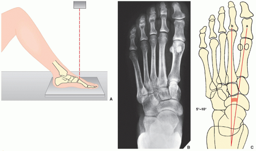
FIGURE 10.21 Anteroposterior view. (A) For the anteroposterior (dorsoplantar) view of the foot, the patient is supine, with the knee flexed and the sole placed firmly on the film cassette. The central beam is directed vertically to the base of the first metatarsal bone. (B) On the radiograph obtained in this projection, injury to the metatarsal bones and phalanges can be adequately assessed. Note that 75% of the talar head articulates with the navicular bone. (For identification of the bones of the foot, see Fig. 10.2.) (C) The first intermetatarsal angle is formed by the intersection of the lines bisecting the shafts of the first (a) and second (b) metatarsals.

Radiographic evaluation of foot injuries is complicated by the presence of multiple accessory ossicles, which are considered secondary centers of ossification, and the sesamoid bones, which may mimic a fracture (Fig. 10.28A,B); conversely, a chip fracture can be misinterpreted as a mere ossicle (Fig. 10.28C,D). Thus, it is important to recognize these structures on conventional radiographs.

In addition to radiography, ancillary imaging techniques may need to be used in the evaluation of injury to the foot. Radionuclide imaging (bone scan) is a valuable means of detecting stress fractures, common foot injuries that are not always obvious on the standard radiographic examination. CT is especially effective in assessing complex fractures, particularly of the calcaneus. Tenographic examination may also be required to evaluate injury to the tendons of the foot (see previous text and Figs. 10.13 and 10.80). MRI is now frequently used to evaluate trauma to the foot. During evaluation of MRI of the ankle and foot, it is helpful to use checklist as provided in Table 10.1.

For a tabular summary of the preceding discussion, see Tables 10.2 and 10.3 and Figure 10.29.


Injury to the Ankle

All ankle injuries can be broadly classified, according to the mechanism of injury, as resulting from inversion (Fig. 10.30) or eversion (Fig. 10.31) stress forces. Inversion injuries are much more common, accounting for 85% of all traumatic conditions involving the ankle. These groupings apply to both fractures and injuries to the ligament complexes of the ankle. However, it is in the latter type of injuries that they are particularly helpful in determining and evaluating the specific type of ligament injury, especially in the presence of certain fractures about the ankle.


Fractures About the Ankle Joint

In addition to being classified by mechanism of injury, fractures about the ankle joint can also be classified by the anatomic structure involved (Fig. 10.32) and designated as:


  • Unimalleolar, when the fracture involves the medial (tibial) or lateral (fibular) malleolus (Figs. 10.33 and 10.34)


  • Bimalleolar, when both malleoli are fractured (Fig. 10.35)


  • Trimalleolar, when fractures involve the medial and lateral malleoli as well as the posterior lip (or tubercle) of the distal tibia (the third malleolus) (Fig. 10.36)


  • Complex fractures, known also as pilon fractures, when comminuted fractures of the distal tibia and fibula occur (Fig. 10.37)


  • Fractures/dislocations (Figs. 10.38 and 10.39).

These fractures, when viewed from the standpoint of pathomechanics, may be either inversion or eversion injuries or a combination of both. The various types of eversion fractures are best known by their eponyms, including the Pott, Maisonneuve, Dupuytren, and Tillaux fractures (see later).

All of the following ankle fractures involving the distal tibia and fibula can be diagnosed on the standard radiographic projections. However, CT may be useful in delineating the extent of the fracture line, and this modality is particularly effective in evaluating lateral displacement in the juvenile Tillaux fracture. To evaluate associated ligament injuries, MRI is the technique of choice.


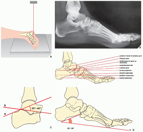
FIGURE 10.22 Lateral view. (A) For the lateral view of the foot, the patient lies on his or her side with the knee slightly flexed and the lateral aspect of the foot against the film cassette. The central beam is directed vertically to the midtarsus. (B) The lateral radiograph demonstrates the bursal projection, the most prominent feature on the posterior aspect of the calcaneus; the posterior tuberosity where the Achilles tendon inserts; the medial tuberosity on the plantar surface where the plantar fascia inserts; the anterior tuberosity; the anterosuperior spine of the calcaneus; the posterior facet of the subtalar joint; the sustentaculum tali; and the talonavicular and calcaneocuboid articulations. The Chopart and Lisfranc joints are also well visualized. (C) The lateral view also allows evaluation of the angular relationship between the talus and the calcaneus—Boehler angle. This feature is determined by the intersection of a line (a) drawn from the posterosuperior margin of the calcaneal tuberosity (bursal projection) through the tip of the posterior facet of the subtalar joint, and a second line (b) drawn from the tip of the posterior facet through the superior margin of the anterior process of the calcaneus. Normally, this angle ranges between 20 and 40 degrees. (D) Calcaneal pitch is described by the intersection of a line drawn tangentially to the inferior surface of the calcaneus and one drawn along the plantar surface of the foot.


FIGURE 10.23 The angle of Gissane. This measurement is obtained on the lateral radiograph of the hindfoot. The angle is formed by intersection of the lines drawn along the downward and upward slopes of the calcaneal dorsal surfaces, with normal values between 125 and 140 degrees.


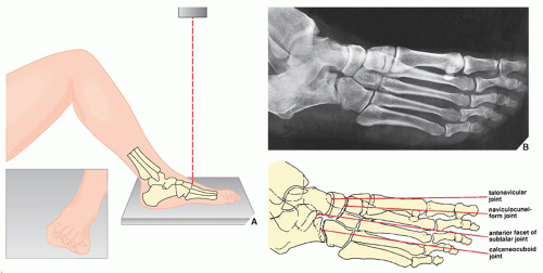
FIGURE 10.24 Oblique view. (A) For the oblique view of the foot, the patient is supine on the table with the knee flexed. The lateral border of the foot is elevated about 40 to 45 degrees (inset) so that the medial border of the foot is forced against the film cassette. The central beam is directed vertically to the base of the third metatarsal. (B) On the oblique radiograph of the foot, the phalanges and metatarsals are well demonstrated, as are the anterior part of the subtalar joint and the talonavicular, naviculocuneiform, and calcaneocuboid joints.


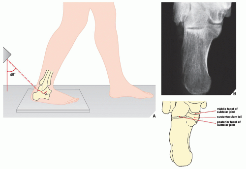
FIGURE 10.25 Harris-Beath view. (A) For the posterior tangential (Harris-Beath) view of the foot, the patient is erect, with the sole of the foot flat on the film cassette. The central beam is usually angled 45 degrees toward the midline of the heel, but 35 or 55 degrees of angulation may also be used. (B) On the radiograph in this projection, the middle facet of the subtalar joint is seen, oriented horizontally; the sustentaculum tali projects medially. The posterior facet projects laterally and is parallel to the middle facet. The body of the calcaneus is well demonstrated.


FIGURE 10.26 Broden view. (A) For the Broden view of the foot, the patient is supine, with the knee slightly flexed and supported by a small sandbag. The foot rests on the film cassette, dorsiflexed to 90 degrees, and, together with the leg, rotated medially approximately 45 degrees (inset). The central beam is directed toward the lateral malleolus. Films may be obtained at 10, 20, 30, and 40 degrees of cephalad angulation of the tube. (B) A radiograph obtained at 30-degree cephalad angulation demonstrates the posterior facet of the subtalar joint. Note also the good demonstration of the sustentaculum tali and the excellent visualization of the talofibular joint and the tibiofibular syndesmosis.


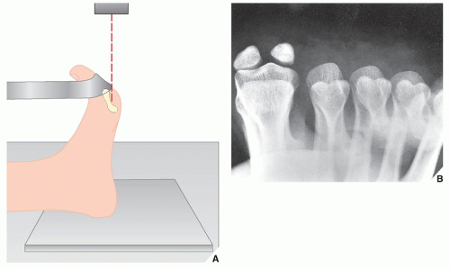
FIGURE 10.27 Tangential view. (A) For a tangential view of the sesamoid bones, the patient is seated on the table, with the foot dorsiflexed on the cassette, holding the toes in a dorsiflexed position with a strip of gauze. The central beam is directed vertically to the head of the first metatarsal bone. (B) This sesamoid view demonstrates the metatarsal heads and the sesamoid bones of the first metatarsal.


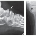
FIGURE 10.28 Accessory ossicles. (A,B) The numerous accessory ossicles of the foot and ankle can complicate the evaluation of foot injuries by mimicking fracture. Fractures, however, may go undetected when misinterpreted as ossicles, as seen here on the anteroposterior (C) and sesamoid (D) views of the foot, which demonstrate a fracture of the lateral (fibular) sesamoid (arrows) (compare with Fig. 10.27B).


TABLE 10.1 Checklist for Evaluation of Magnetic Resonance Imaging of the Foot and Ankle


Osseous Structures


Distal tibia (c, s)


Distal fibula (c, s)


Talus (c, s, a)


Calcaneus (c, s, a)


Cuboid (s, a)


Navicular (s, a)


Cuneiform—medial, middle, lateral (c, a)


Sesamoid bones (c, a)


Os naviculare (external tibial ossicle) (a)


Peroneal ossicle (c, s)


Joints and Articular Cartilage


Tibiotalar (c, s)


Chopart (s)


Lisfranc (s)


Subtalar (c, s)


Muscles and Their Tendons


Achilles (s, a)


Tibialis anterior (a)


Tibialis posterior (a)


Peroneus—longus, brevis, tertius (a)


Flexor hallucis longus (s, a)


Flexor hallucis brevis (s, a)


Extensor hallucis longus (s, a)


Extensor hallucis brevis (s, a)


Flexor digitorum—longus, brevis (s, a)


Extensor digitorum—longus, brevis (s, a)


Plantaris (a)


Abductor hallucis (a)


Adductor hallucis (a)


Ligaments


Deltoid


Tibiocalcaneal band (c)


Tibiotalar band—anterior, posterior (c, a)


Tibionavicular band (s, a)


Spring (tibio-spring) (c, a)


Lateral collateral


Posterior talofibular (a)


Anterior talofibular (a)


Calcaneofibular (c)


Distal tibiofibular syndesmosis


Interosseous membrane (c, a)


Posterior tibiofibular (c, a)


Anterior tibiofibular (c, a)


Inferior transverse (a)


Lisfranc (a)


Bursae


Retrocalcaneal (s)


Retro-Achilles (s, a)


Other Structures


Fascia plantaris (s)


Plantar plate (s)


Sinus tarsi (c, s, a)


Tarsal tunnel (c, s, a)


Anterolateral gutter (a)


Kager fat pad (s)


Tibial artery, vein, nerve (a)


Greater saphenous vein (a)


The best imaging planes for visualization of listed structures are given in parenthesis; c, coronal (coronal of ankle, short-axis axial of foot); s, sagittal; a, axial (axial of ankle, long-axis axial of foot).


TABLE 10.2 Standard and Special Radiographic Projections for Evaluating Injury to the Ankle and Foot


Projection


Demonstration


Anteroposterior (ankle)


Fractures of


Distal tibia


Distal fibula


Medial malleolus


Lateral malleolus


Pilon fractures (extension into tibiotalar joint)


(foot)


Fractures of


Talus (particularly dome)


Navicular, cuboid, and cuneiform bones


Metatarsals and phalanges (including stress fractures and accessory ossicles)


Dislocations in


Subtalar joint


Peritalar (anterior and posterior types)


Total talar


Tarsometatarsal (Lisfranc) joint


With 10 degrees of internal ankle rotation (mortise view)


Same structures and abnormalities as anteroposterior but better demonstration of tibial plafond


Stress (inversion, eversion)


Tear of lateral collateral ligament


Tear of deltoid ligament


Ankle instability


Lateral (ankle and foot)


Boehler angle


Angle of Gissane


Fractures of


Distal tibia


Anterior aspect


Posterior lip (third malleolus)


Tibiotalar joint


Talus (particularly neck)


Calcaneus (particularly in coronal plane)


Posterior facet of subtalar joint


Sustentaculum tali


Accessory ossicles


Cuboid bone


Dislocations in


Ankle joint


Subtalar joint


Peritalar (anterior and posterior types)


Tarsometatarsal (Lisfranc) joint


Ankle joint effusion


Stress (anterior-draw)


Tear of anterior talofibular ligament


Ankle instability


Oblique


Fractures of


Internal


Medial malleolus


External


Talus


Tuberosity of calcaneus


Metatarsals


Phalanges


Posterior tangential (Harris-Beath)


Fractures involving


Middle and posterior facets of subtalar joint


Calcaneus (in axial plane)


Oblique tangential (Broden)


Fractures involving


Posterior facet of subtalar joint


Calcaneus


Sustentaculum tali


Axial (sesamoid view)


Fractures of sesamoid bones


TABLE 10.3 Ancillary Imaging Techniques for Evaluating Injury to the Ankle and Foot


Technique


Demonstration


Radionuclide imaging (scintigraphy, bone scan)


Arthrography (single-contrast) (double-contrast, usually combined with tomography or CT)


Stress fractures


Healing process


Tears of ligament structures of ankle joint


Osteochondral fractures


OCD of talus


Osteochondral bodies in joint


Tenography


Tears of


Achilles tendon


Posterior tibialis tendon


Peroneal tendons


Digitorum longus tendon


CT


Complex fractures (particularly of os calcis)


Intraarticular extension of fracture line


Injuries to tendons (particularly peroneal, tibialis, and Achilles) and ligaments


MRI


Same as arthrography, tenography, and CT


Tarsal tunnel syndrome


Sinus tarsi syndrome


US


Traumatic injuries of tendons and ligaments


Posttraumatic hematomas and fluid accumulation in the soft tissues


Tarsal tunnel syndrome


Sinus tarsi syndrome


CT, computed tomography; OCD, osteochondritis dissecans; MRI, magnetic resonance imaging; US, ultrasound.


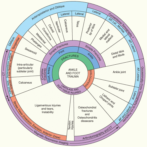
FIGURE 10.29 Spectrum of radiologic imaging techniques used to evaluate trauma to the ankle and foot. The radiographic projections or radiologic techniques indicated throughout the diagram are only those that are the most effective in demonstrating the respective traumatic conditions. #Replaced almost completely by CT. AP, anteroposterior; Lat., lateral; CT, computed tomography; Conv., conventional; r/o, rule out.


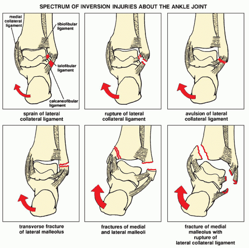
FIGURE 10.30 Inversion injuries. Depending on its severity, an inversion force (red arrows) delivered to the lateral structures of the ankle joint may manifest in a broad spectrum of injuries of the lateral collateral ligament complex as well as the lateral and medial malleoli. Note, however, that inversion-stress forces do not affect the posterior tibiofibular or medial collateral ligaments. (Modified from Edeiken J, Cotler JM. Ankle trauma. Semin Roentgenol 1978;13: 145-155.)


FIGURE 10.31 Eversion injuries. Depending on its severity, an eversion force delivered to the medial structures of the ankle joint may manifest in a broad spectrum of injuries of the medial collateral (deltoid) ligament complex as well as the medial and lateral malleoli. Note, however, that eversion-stress forces do not affect the posterior tibiofibular or lateral collateral ligaments. (Modified from Edeiken J, Cotler JM. Ankle trauma. Semin Roentgenol 1978;13:145-155.)


FIGURE 10.32 Classification of ankle fractures. Ankle fractures can be classified according to the anatomic structure as unimalleolar, bimalleolar, trimalleolar, or complex.


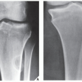
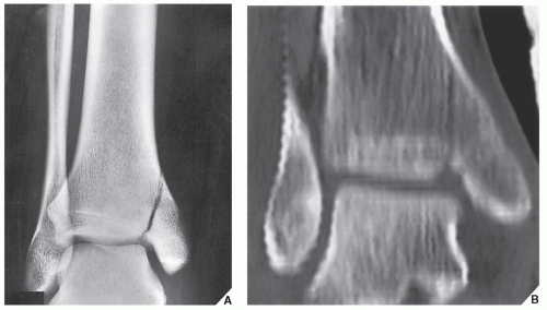
FIGURE 10.33 Unimalleolar fracture. Anteroposterior radiograph of the ankle (A) and coronal CT reformatted image (B) demonstrate the typical appearance of a unimalleolar fracture involving the medial malleolus.


FIGURE 10.34 Unimalleolar fracture. Anteroposterior radiograph of the left ankle shows a transverse fracture of the lateral malleolus.


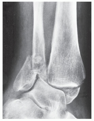
FIGURE 10.35 Bimalleolar fracture. Oblique radiograph of the ankle shows a bimalleolar fracture involving the tibial and fibular malleoli.


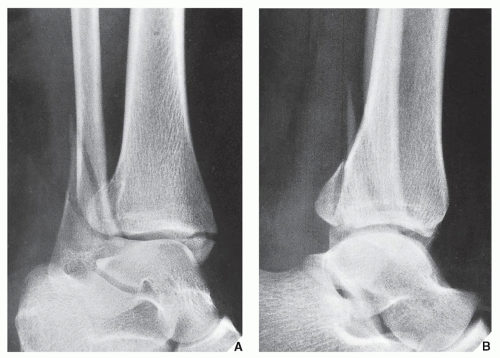
FIGURE 10.36 Trimalleolar fracture. Oblique (A) and lateral (B) radiographs of the ankle show a trimalleolar fracture affecting both malleoli and the posterior lip of the distal tibia. The latter feature is better seen on the lateral projection.


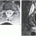
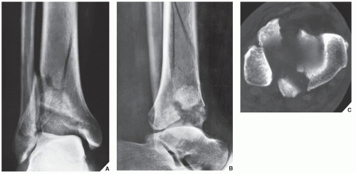
FIGURE 10.37 Pilon fracture. Anteroposterior (A) and lateral (B) radiographs of the ankle demonstrate a complex, comminuted fracture of the distal tibia and fibula in a 30-year-old man who fell from a third-floor window. (C) Axial CT section through the tibial plafond shows typical appearance of pilon fracture.


FIGURE 10.38 Fracture/dislocation of the ankle. A 28-year-old woman injured her right ankle in a skiing accident. Note comminuted fractures of the distal fibula and medial malleolus associated with posterior dislocation in the ankle joint.


FIGURE 10.39 3D CT of fracture/dislocation of the ankle. (A) Anteroposterior and (B) cross-table lateral radiographs of the left ankle show trimalleolar fracture associated with posterior dislocation in the ankle joint. (C) Coronal reformatted and (D) 3D reconstructed CT images were obtained after the dislocation was relocated.

Only gold members can continue reading. Log In or Register to continue

Stay updated, free articles. Join our Telegram channel

Jul 24, 2016 | Posted by in MUSCULOSKELETAL IMAGING | Comments Off on Lower Limb III: Ankle and Foot

Full access? Get Clinical Tree

Get Clinical Tree app for offline access