Fig. 4.1
(a) Time-resolved CE MRA with fast temporal resolution (≤2 s/image) is used to determine time-to-peak enhancement in the vessel of interest, in this case the aorta. This can be done visually or quantitatively by drawing a region of interest over the aorta (yellow circle) and assessing the signal intensity–time curve (b) to determine the precise time-to-peak enhancement. Typically, a diagnostic delay (~4–6 s) is added to the time to peak from the test bolus injection due to different amounts of contrast injected between the test bolus and actual 3D CE MRA
High-Resolution Static CE MRA
High spatial resolution CE MRA is performed using a 3D spoiled gradient-recalled echo sequence, timed such that the central k-space lines are acquired during peak enhancement of the vessels of interest. Because of the high spatial resolution that can be achieved using modern sequences, typically ≤1.5 mm isotropic, these sequences are used to delineate the complex anatomical structures in patients with CHD (Fig. 4.2). Although previously limited to relatively narrow 3D volumes, improvements in software and hardware design discussed in subsequent paragraphs have enabled substantial accelerations in image acquisition so that it is now possible to obtain high-resolution CE MRA images of the entire thorax (Fig. 4.3) within a short breath hold.
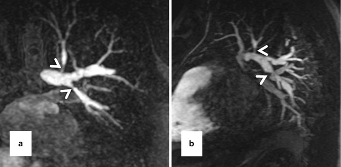
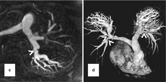
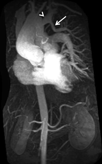
Fig. 4.2
High-resolution 3D CE MRA in 28-year-old male with Alagille syndrome causing multiple branch pulmonary artery stenoses (arrowheads). Because of the isotropic spatial resolution, it is possible to generate high-quality (a) coronal, (b) sagittal, and (c) axial multiplanar reformatted and (d) volume-rendered images to assess the anatomy and morphology of the cardiovascular system
Fig. 4.3
Maximum intensity projection image from 3D CE MRA of the entire thorax in patient with repaired tetralogy of Fallot and partial anomalous venous return from the left upper lobe (arrow). The anomalous pulmonary vein drains into the left brachiocephalic vein (arrowhead)
Contrast Administration
For the majority of CE MRA applications, a single dose of standard, extracellular GBCA (0.1 mmol/kg) is sufficient. Contrast is injected intravenously (IV) through a catheter (preferably through an 18–22 gauge catheter in an antecubital vein) at a variable rate (i.e., 0.5–4.0 mL/s), depending upon the size of the catheter, the quality of the patient’s veins, and the length of the acquisition. However, caution should be used when injecting high relaxivity GBCA because when injecting at a high rate, the concentration of GBCA can be high enough to cause T2-star artifact, reducing the overall signal intensity within the vasculature during the first pass (Fig. 4.4). As indicated previously, the image acquisition is timed such that the center of k-space is acquired during maximum enhancement of the vessels of interest, because the center of k-space contributes to the overall signal and enhancement of the image, while the peripheral of k-space contributes to the detail or sharpness of the images (Fig. 4.5). The time-to-peak enhancement of the vessels of interest can be done using a test bolus injection to determine the transit time of a contrast injection from the peripheral IV to the area being imaged [1]. Alternatively, with centric k-space ordering, where the center of k-space is acquired at the beginning of the scan, real-time bolus tracking can be used so that the acquisition can be started precisely when the contrast bolus arrives in the vessels of interest [2]. When the acquisition is not timed appropriately to the passage of the contrast bolus, a variety of different artifacts can occur, including decreased signal-to-noise ratio (SNR), truncation artifact, and edge blurring [3]. Ideally, the contrast bolus injection duration should be equal to the length of acquisition (Fig. 4.6). A benefit of CE MRA, relative to CT angiography (CTA), is that if the image quality is insufficient to make the diagnosis, the acquisition can be repeated with a second injection (Fig. 4.7) with little to no harm to most patients because GBCA is less nephrotoxic and MRA does not require the use of ionizing radiation.
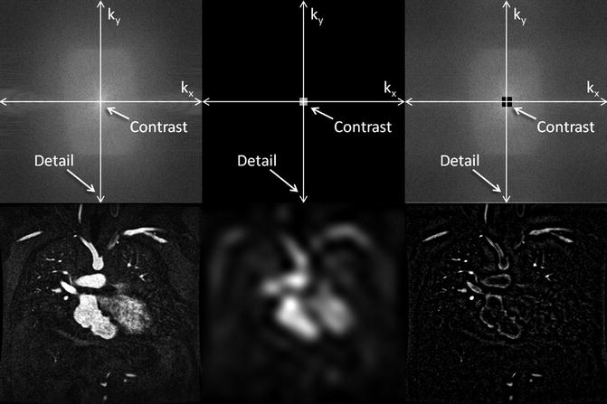
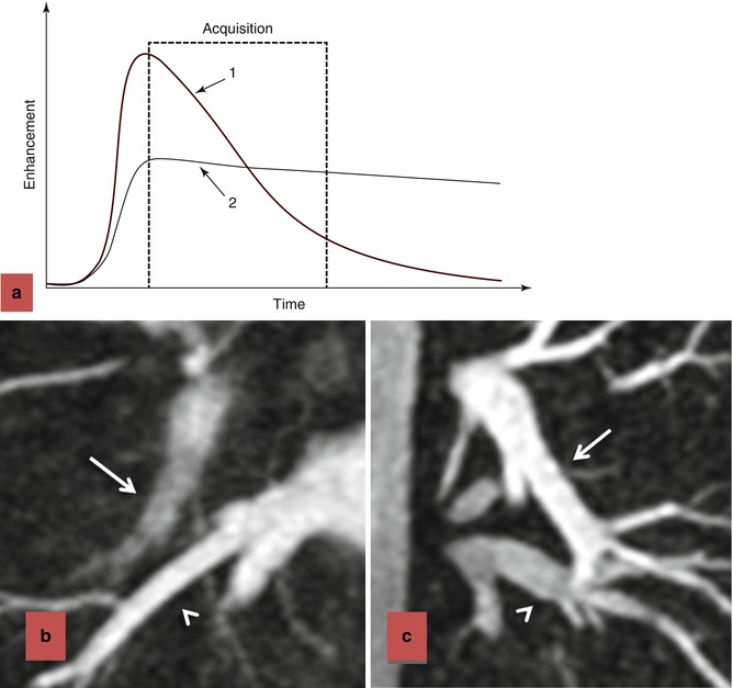
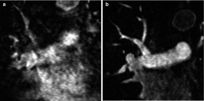
Fig. 4.4
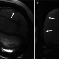
(a) T2-star effects of rapid GBCA injection decrease the signal intensity in the left brachiocephalic vein (arrows). (b) During recirculation, when contrast has been diluted with non-enhanced blood, enhancement of the venous structures is more uniform without any central decrease signal intensity (arrows). MPA main pulmonary artery, Ao aorta
Fig. 4.5
K-space (top row) and image space (bottom row) images from contrast-enhanced MRA illustrating the differences between fully sampled k-space (left), central k-space (middle), and outer k-space (right) data. The central k-space data contributes to the overall signal of the image, which for contrast-enhanced MRA provides the signal in the vasculature. However, the corresponding image is very blurry. The outer regions of k-space encode for the edges, resulting in images that have sharp vessel definition, but with very little vascular enhancement
Fig. 4.6
Effects of contrast bolus duration on edge blurring. (a) Enhancement time diagram demonstrating two injection strategies. In injection 1, contrast is injected rapidly, resulting in rapid upslope in enhancement and rapid washout. Although there is bright signal during the early part of the acquisition, resulting in intense contrast enhancement, the later stages of the acquisition occur during diminished enhancement. The loss of signal during the acquisition of the outer regions of k-space results in blurring of the vessels in which the contrast has washed out (b). When the contrast is injected more slowly, as in strategy 2, there is more uniform enhancement throughout the acquisition of k-space. The persistence of enhancement throughout the acquisition, including the higher-order k-space lines, results in improved vascular sharpness (c). In (b), the acquisition was 18 s and the bolus duration was 8 s. Although the pulmonary veins (arrowhead) are bright and very sharp, the pulmonary arteries (arrow) are blurry and poorly enhanced. In (c), the acquisition was 18 s and the bolus duration was 20 s. In this case, pulmonary arteries (arrow) and pulmonary veins (arrowhead) are very sharp and sufficiently enhanced
Fig. 4.7
(a) Image quality of the initial CE MRA is nondiagnostic due to respiratory motion during the acquisition. (b) The CE MRA was repeated after instructing the patient to hold their breath during the entire acquisition, resulting in very high-quality CE MRA with very sharp vessels
At our institution, we dilute a single dose of GBCA [i.e., 0.1 mmol/kg of gadobenate dimeglumine (Multihance, Bracco Diagnostics Inc. Princeton, NJ, USA) or 0.03 mmol/kg of gadofosveset trisodium (Vasovist, ABLAVAR, EPIX Pharmaceuticals, Inc. Cambridge, MA, USA)] with normal saline to achieve a total volume of 30 mL to inject in two phases. We inject 5 mL of diluted contrast at 2 mL/s, resulting in a 2.5 s contrast bolus which we expect to prolong to 3–4 s by the time it gets to the pulmonary circulation, for the time-resolved CE MRA (which has a “temporal resolution” of 3–4 s). We then inject 25 mL at 1.5 mL/s, resulting in a 16–17 s contrast bolus which we expect to prolong to ~20 s by the time it reaches the pulmonary circulation, for the high-resolution 3D CE MRA, which is about 17–20 s long.
ECG Triggering
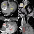
Conventional three-dimensional (3D) CE MRA can be performed without or with ECG triggering. ECG-triggered CE MRA (Fig. 4.8) is preferred for imaging patients with diseases of the ascending aorta to minimize artifact from cardiac motion [4]. Furthermore, when making measurements of the aorta, or other vessels, it is critical to make double-oblique measurements perpendicular to the vessel long axis (Fig. 4.8b) rather than simply using axial images to avoid overestimating the true size of the vessel [5]. Equally important is to use a consistent method of defining how the measurements are being made, especially when using MRA-derived measurements in comparison with prognostic data obtained using other imaging modalities [6]. A limitation of ECG-triggered CE MRA techniques is that they require more time to acquire and is therefore potentially problematic in patients who have difficulty holding their breath. Acquisition times for ECG-triggered CE MRA can be decreased by limiting the coverage to a thin slab over the aorta or by using parallel imaging.
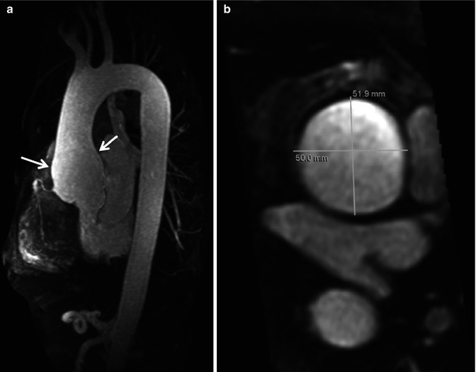
Fig. 4.8
Electrocardiographic (ECG) gated CE MRA in patient with aortic root aneurysm. Use of cardiac gating results in acquisition of images free of cardiac motion artifact. (a) On the maximum intensity projection image, the entire ascending aorta, including the aortic root, is well defined with very sharp vessel walls (arrows). This is critical when making double-oblique measurements to quantify the maximum dimensions of the aorta (b)
Parallel Imaging
A major advance in improving the speed of MR image acquisition has been the use of parallel imaging [7–9]. This has been enabled through changes in image reconstruction from undersampled k-space data and use of multichannel receiver coils [10]. With these multichannel receiver coils, each individual coil is used to simultaneously receive the MR signal. The use of parallel imaging to accelerate data acquisition can be used to shorten the scan times to image the same volume [11] or to increase anatomical coverage during the same acquisition time [12]. Using advanced parallel imaging techniques, it is now possible to scan the entire thoracic vasculature within 15–20 s with high, isotropic spatial resolution (Fig. 4.9).
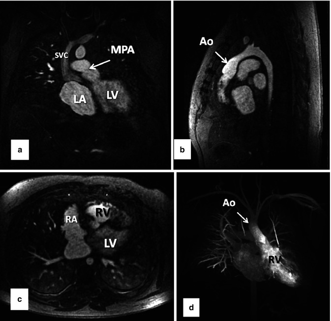
Fig. 4.9
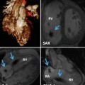
Thirty-two-year-old male with d-TGA status post Mustard procedure. (a) Coronal, (b) sagittal, and (c) axial MPR images from whole chest CE MRA acquired using 2D parallel imaging to accelerate image acquisition ~3.75×. With advanced parallel imaging, acquisition times are decreased sufficiently to acquire images of the entire chest within a short breath hold. Data are isotropic in all three dimensions, enabling high-resolution multiplanar reformation and 3D maximum intensity projection images (d) to be generated. LV left ventricle, LA left atrium, RV right ventricle, RA right atrium, SVC superior vena cava, MPA main pulmonary artery, Ao aorta
CE MRA at 3.0T
A major motivation for scanning at higher field strengths is that the SNR is proportional to the field strength. Therefore, at 3.0T SNR is approximately twice that at 1.5T. The advantage in SNR at 3.0T, relative to 1.5T, can be used to increase spatial resolution, decrease scan time, or a combination of these while obtaining images of relatively similar or better quality as those at 1.5T [13]. In addition, because of the differences in T1 effects of GBCA at 3.0T, there is actually greater vascular contrast, relative to surround soft tissues, at 3.0T compared to 1.5T. Therefore, CE MRA at 3.0T can be performed with smaller doses of GBCA [14–17]. In fact, recent data suggests smaller volumes of GBCA result in higher-quality arterial phase MRA than with larger volumes of GBCA [18].
MRI at 3.0T results in significant challenges and limitations due to the stronger magnetic field that have not yet been fully overcome. At 3.0T, the resonance frequency of water protons is double that at 1.5T. Because the frequency and wavelength are inversely related, the radiofrequency (RF) wavelength of water protons at 3.0T is half that at 1.5T. This shortened wavelength can span the dimensions of the field of view for body imaging, especially in those with a large body habitus [19]. When RF waves overlap within the imaging field, destructive or constructive interference results in areas of darkening or brightening, respectively. RF field homogeneity can be improved by (A) using advanced coil designs, such as multi-coil transmit coils, which can help to suppress eddy currents [20] or (B) implementing new pulse sequences, such as 3D RF pulses [21].
Another potential limitation with performing MRA at 3.0T is that the specific absorption rate (SAR) increases at higher field strengths due to constructive and destructive interference due to RF field inhomogeneity. RF pulses transfer energy to protons within the patient and ultimately generate heat as energy is released. To avoid overheating within the patient, which can have detrimental physiologic effects, the SAR is carefully monitored during scanning. The FDA currently limits the total body heating to 4 W/kg during a 15-min period [22, 23]. The SAR estimates the energy transfer to the tissue by the RF pulse and is proportional to the square of the resonance frequency. Therefore, in going from 1.5 to 3.0T, where the resonance frequency is doubled, the SAR increases fourfold for the same sequence, assuming all parameters are equal [24]. As a result, the pulse sequences, acquisition techniques, and hardware designs are modified to work within the allowable constraints of the increased SAR. Parallel imaging helps alleviate this problem by decreasing scan time and the number of RF pulses necessary to acquire an image.
Blood-Pool Contrast Agents
Most CE MRA, as with most CE MRI, is performed with GBCA that are not purely intravascular. Rather, most GBCAs do distribute throughout the extracellular space. For vascular imaging, however, this can be problematic in achieving the greatest contrast between the vessels and their surrounding soft tissues. Intravascular GBCAs are, therefore, another recent advance that has enabled improvement in CE MRA spatial and contrast resolution. Gadofosveset trisodium, the currently only FDA-approved blood-pool GBCA, is a protein-binding intravascular contrast agent that is approved for the evaluation of patients with aortoiliac occlusive disease [25]. Protein binding is what prolongs the intravascular half-life of gadofosveset trisodium relative to other GBCAs. Another factor contributing to its advantage for CE MRA is that gadofosveset trisodium has a higher relaxivity than other GBCAs [26]. Due to its intravascular distribution and greater contrast enhancement, smaller volumes of gadofosveset trisodium are necessary than other GBCAs to achieve the same image quality [27, 28]. Furthermore, the prolonged intravascular half-life extends the amount of time available for scanning during vascular enhancement. Therefore, very high spatial and contrast resolution CE MRA images are feasible during the steady state (Fig. 4.10) which may be beneficial in detecting additional findings not present on first-pass CE MRA [29, 30]. In addition, the prolonged intravascular enhancement with blood-pool contrast agents implies that high-quality imaging can be performed during free breathing using respiratory navigators or bellows for triggering to the same part of the respiratory cycle. This is particularly useful in patients that have difficulty holding their breath [29]. CE MRA during the steady state can also be particularly helpful in patients with cavopulmonary shunts because during the first pass, unenhanced blood from the inferior vena cava will dilute the contrast entering the pulmonary circulation from the superior vena cava.
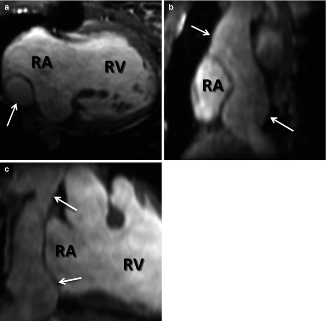
Fig. 4.10
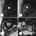
Steady-state CE MRA using navigator respiratory triggering after administration of blood-pool contrast agent. (a) Axial, (b) sagittal, and (c) coronal reformatted images delineate anatomy of extracardiac Fontan (arrows) in this patient with double outlet right ventricle (RV). RA right atrium
Time-Resolved CE MRA
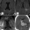
Time-resolved CE MRA can help overcome some of the limitations of static 3D CE MRA techniques. A major advantage of time-resolved sequences is the lack of need for precise timing of the acquisition relative to the contrast bolus because data are acquired continuously during the passage of GBCA from the IV catheter throughout the vasculature (Fig. 4.11). There are now multiple methods of accelerating image acquisition to achieve high temporal resolution CE MRA. One method of achieving sub-second temporal resolution is through the use of three-dimensional, asymmetric k-space undersampling combined with thicker slice thickness in the slice-encoding direction [31]. However, because of the relatively thick slice thickness, these acquisitions do not lend themselves to high-quality multiplanar reformations necessary to evaluate the complex anatomy in patients with CHD. To acquire time-resolved data while preserving relatively high spatial information, other approaches are used to accelerate data acquisition based on k-space undersampling. These are based on acquiring the higher spatial frequencies less frequently [32–35]. As indicated previously, the central k-space data contributes to the high vascular signal, while the outer k-space data contributes to vessel sharpness. Therefore, by updating the center of k-space more frequently and “sharing” the outer regions of k-space between multiple updates of the center of k-space, it is possible to generate images with high contrast, high temporal resolution, and high spatial resolution. To improve the vascular enhancement and SNR of time-resolved CE MRA, a fully k-space sampled non-contrast dataset, or mask, is typically acquired first (Fig. 4.12a). Undersampled k-space images are the acquired during the administration of GBCA (Fig. 4.12b). To generate images with purely vascular signal, the mask images are subtracted from these contrast-enhanced datasets (Fig. 4.12c).
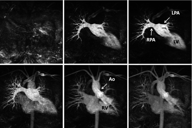
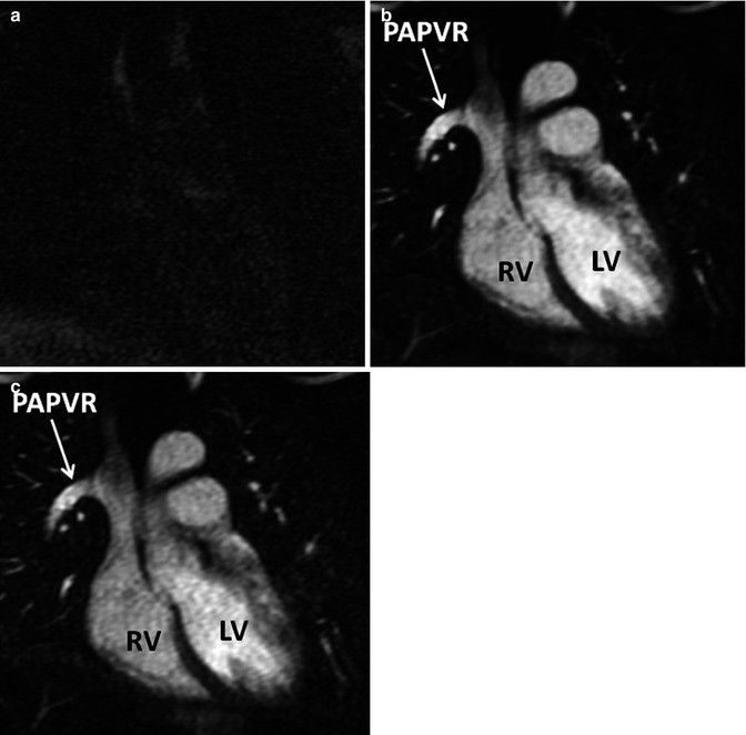
Fig. 4.11
Twenty-year-old male with d-TGA status post Mustard procedure. Maximum intensity images reconstructed from multiple datasets from a time-resolved contrast-enhanced MRA acquisition show asymmetric perfusion of the lungs, with greater perfusion of the right lung than the left lung. LV left ventricle, RV right ventricle, RPA right pulmonary artery, LPA left pulmonary artery, Ao aorta
Fig. 4.12
In time-resolved CE MRA, a mask dataset (a) is acquired first, prior to the administration of contrast material. Data is then acquired continuously after the injection of contrast to obtain multiple contrast-enhanced MRA datasets (b). To remove the background signal, the mask is subtracted from each of the contrast-enhanced dataset to generate images with purely intravascular signal (c). RV right ventricle, LV left ventricle, PAPVR partial anomalous pulmonary venous return
In patients with CHD, time-resolved CE MRA is useful because of the dynamic information that can be obtained from these datasets including transit times through the lungs [36, 37] and relative pulmonary perfusion [38]. This functional information is complementary to the high spatial resolution information obtained from the static 3D CE MRA acquisitions [39]. The relative temporal resolution of time-resolved CE MRA can be adjusted by changing the different parameters to achieve the desired balance between temporal and spatial resolution (Fig. 4.13).
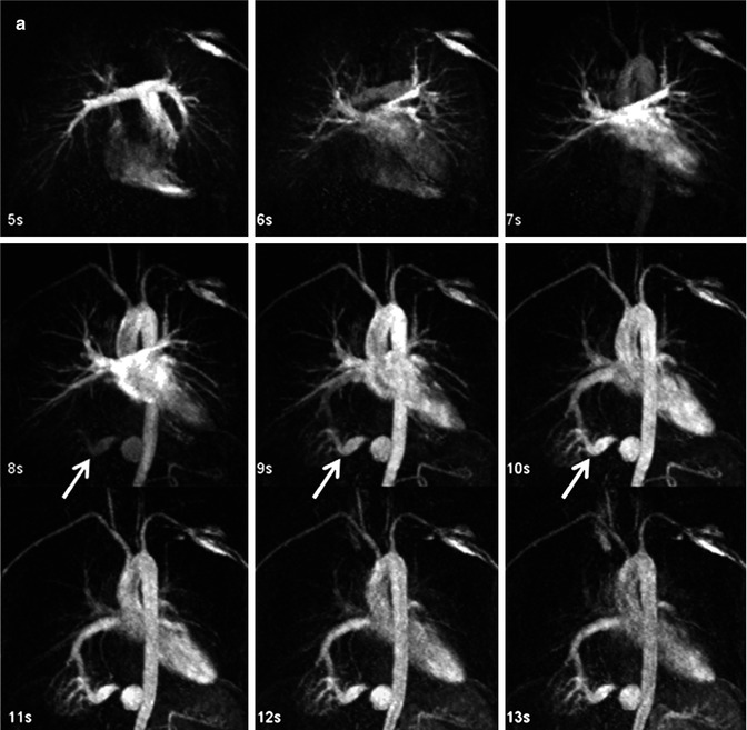
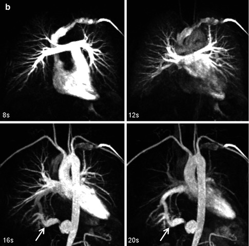
Fig. 4.13
Time-resolved contrast-enhanced MRA (TR CEMRA) with (a) 1-s and (b) 4-s reconstructed temporal resolution. While the faster temporal resolution TR CEMRA provides greater information on the high flow dynamics through the anomalous artery going to the right lower lobe sequestration (arrow), the lower temporal resolution TR CEMRA has higher spatial resolution and can be used to provide more precise measurements of the vessels
Non-Contrast-Enhanced MRA
Long acquisition times and artifacts from cardiac and respiratory motion have traditionally limited the use non-contrast-enhanced (NCE) MRA for cardiothoracic applications. However, improvements in MR software and hardware, as well as concerns over the safety of GBCA in high-risk patient groups, have fostered a renewed interest in NCE MRA. Research linking the administration of GBCA to the development of nephrogenic systemic fibrosis (NSF) in patients with reduced renal function [40–42] has been a primary motivation for expanding the use of NCE MRA for a variety of applications, including thoracic MRA. NCE MRA is also of clinical interest in evaluating patients with other contraindications to GBCA, including poor IV access, pregnancy, or prior allergic reactions to GBCA. Although time-of-flight (TOF) sequences are still used routinely for cervical and intracranial MRA, with diagnostic comparable to CTA and DSA [43, 44], their use in the thorax is markedly limited. In this section, we will review the two main NCE MRA sequences used for cardiothoracic applications, balanced steady-state free precession (bSSFP) and phase-contrast (PC) MRA.
3D bSSFP
For cardiothoracic NCE MRA, 3D bSSFP sequences (Figs. 4.14 and 4.15) are most often used because of (a) inherently high signal of blood compared to surround soft tissues and (b) relative blood flow independence [45]. Image contrast of bSSFP sequences are determined by the ratio of T2 to T1 of the tissues, which results in the very bright blood-pool signal. Standard 3D bSSFP techniques will produce images that have bright arterial and venous signal, which is typically not a problem for assessment of the larger, central vessels like the aorta, main pulmonary arteries, or pulmonary veins [46–49]. 3D bSSFP MRA is also widely used for coronary MR angiography [50, 51]. These sequences are typically performed using respiratory triggering or navigation to minimize respiratory motion artifacts and ECG triggering to minimize cardiac motion artifacts. However, a limitation of the bSSFP sequence is its susceptibility to field inhomogeneities which occur at the lung–soft tissue interfaces and around metallic implants or devices.
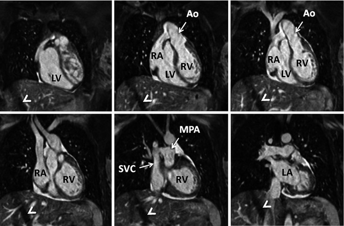
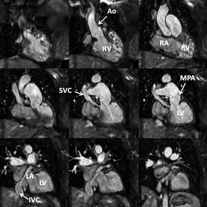
Fig. 4.14
3D balanced SSFP MRA performed without IV contrast and during free breathing using respiratory navigator triggering. High contrast-to-noise and spatial resolution enable accurate assessment of anatomy in this patient with congenitally corrected transposition of the great arteries. The diagonal bands of low signal intensity crossing the right lobe of the liver (arrowheads) are related to the navigator. LV left ventricle, LA left atrium, RV right ventricle, RA right atrium, SVC superior vena cava, MPA main pulmonary artery, Ao aorta
Fig. 4.15
3D balanced SSFP MRA performed without IV contrast and during free breathing using respiratory navigator triggering. High contrast-to-noise and spatial resolution enable accurate assessment of anatomy in this patient with a history of Mustard procedure to repair D-transposition of the great arteries. There is a surgical baffle (dashed line) connecting the vena cava (SVC, IVC) to the left atrium (LA), which is connected to the left ventricle (LV) and then the main pulmonary artery (MPA). Pulmonary venous return is directed to the right atrium (RA), right ventricle (RV), and into the aorta (Ao)
For quantitative measurements of vessel size in the thorax, 3D bSSFP MRA performs very well in comparison with CE MRA. In a comparison of 3D bSSFP and CE MRA, François et al. [46


Related posts:
Stay updated, free articles. Join our Telegram channel
Full access? Get Clinical Tree
