(1)
Department of Radiology, Saitama Medical University, Moroyama, Saitama, Japan
Abstract
It is not possible to diagnose ACL pathology using sagittal MR images acquired with fully or overextended knees.
2.1 Positioning and Fixation of the Knee
It is not possible to diagnose ACL pathology using sagittal MR images acquired with fully or overextended knees.
It is therefore important that the knee is slightly flexed within the coil (see Chap. 3 for more details).
2.2 Acquisition of Images in the Sagittal Plane
It is essential that the range of image acquisition covers the entire femoral condyles and the tibial plateau from the medial to the lateral edge in the axial image (Fig. 2.1).
Fig. 2.1
Setup of sagittal slices (right knee). In this example, there are only 17 slices, but ideally, there should be more than 25 slices at slice thickness of 3 mm to visualize fine changes in cartilage and menisci
In a typical adult male patient, more than 25 slices will be required at the slice thickness of 3 mm.
In old days, acquisition of MR images in diagonal slices was severely limited by foldover artifacts. In those circumstances, it was necessary to externally rotate the distal lower limb by 15–20° to visualize ACL, which runs diagonally across the intercondyloid fossa, in sagittal images.
Thanks to improvement in both hardware and software in MR imaging, this limitation has become less significant. However, one should be careful not to unnecessarily internally or externally rotate the knee to prevent distortion of ligamentous structures including cruciate and collateral ligaments (Fig. 2.2).
Fig. 2.2
Exampleof unsuccessful image acquisition due to excessive external rotation of the distal lower limb (right knee). Excessive external rotation of the distal lower limb leads to the direction of sagittal slice paralleling the lateral wall of intercondyloid fossa (a). In sagittal images, there will be partial volume effect from the bone cortex, which also hinders the delineation of ACL (b, arrows)
In sagittal acquisition, direction of phase encoding is usually anterior to posterior. In this case, however, images will be hindered by artifacts arising from blood flow in the popliteal artery and vein (Fig. 2.3). This can be prevented by setting the phase encoding direction to superior to inferior, but one should attempt to minimize foldover artifacts.
Fig. 2.3
Bloodflow artifacts arising from inappropriate phase encoding direction. In sagittal acquisition, direction of phase encoding is usually anterior to posterior. In this case, however, images will be hindered by artifacts (a, arrows) arising from blood flow in the popliteal artery and vein (*). This can be prevented by setting the phase encoding direction to superior-to-inferior (b)
2.3 T1-Weighted and Proton Density-Weighted Fast Spin-Echo Sequences
Although both T1- and T2-weighted images are automatically acquired at many institutions without much consideration, T1-weighted images do not have much value in delineating ligamentous and meniscal lesions.
Normal ligaments and menisci show low intensity signals, and thus proton density- or intermediate-weighted images will allow better contrast with the surrounding cartilage and joint fluid (Fig. 2.4).
Fig. 2.4
Comparisonof T1WI and intermediate-weighted (close to PDW) images. (a) and (c) T1WI (SE 350/14). (b) and (d) intermediate-weighted (close to PDW) images (FSE 1.324/17, ET 5). The latter demonstrates the margins of ACL and cartilage better than the T1WI, also with a better contrast of meniscal tear (d, arrow)
Fast spin-echo (FSE) sequence requires much shorter acquisition time compare to conventional spin-echo (SE) sequence and enables acquisition of images with higher anatomical resolution. Thus, FSE is often utilized in knee MRI. However, one needs to be cautious regarding the following issues:
Echo train length (ETL) should be kept to the minimum to prevent occurrence of blurring of image.
Fat may be depicted as hyperintensity and may lower the contrast against meniscal lesions. This can be prevented by application of fat suppression.
To acquire proton density-weighted FSE images, ETL should be kept to the minimum (max 5 or 6).
Using proton density-weighted FSE sequences with water-highlighted technique (adding –90° pulse at the end of the echo train to forcefully recover vertical magnetization, such as DRIVE (Philips), FRFSE (GE), RESTORE (Siemens) and T2 Plus (Toshiba)), one can emphasize the T2-weighted contrast even with a relative short TR. Joint fluid will be depicted as hyperintensity and with better delineation of cartilage, ligaments, and menisci (Fig. 2.5).
Fig. 2.5
PDWI with DRIVE (a), in which joint fluid is depicted as hyperintensity, and conventional PDWI (b). In (a), joint fluid is depicted as hyperintensity which creates better contrast with cartilage and ACL, allowing these structures to be more clearly delineated (FOV 150 mm, slice thickness 3 mm, slice gap 0.3 mm, 23 slices, 512 scan matrix, 864 ZIP, scan time 6 m)
2.4 Magic Angle Effect
The magic angle effect is a phenomenon that results in artifactual hyperintensity in structures with ordered collagen, such as tendons and ligaments. This is because when collagen is oriented at 55° to the main magnetic field, dipole-dipole interactions becomes zero, resulting in a prolongation of T2 relaxation time.
Care must be taken not to mistake this as a pathological finding such as a ligamentous tear.
Magic angle effect is particularly notable with short TE sequences such as T1-weighted, proton density-weighted, or T2*-weighted (which is based on a gradient-recalled echo sequence using a low flip angle) sequences (Fig. 2.6).
Fig. 2.6
Magic angle effect affecting the patellar tendon. T2*WI (GRE 560/14, flip angle 30°). Superior aspect of the patellar tendon exhibits localized hyperintensity (arrows). This phenomenon can be seen when the tendon is oriented at 55° to the main magnetic field (Bo, superior-inferior direction)
Magic angle effect can also affect the posterior horn of the lateral meniscus (Fig. 2.7).
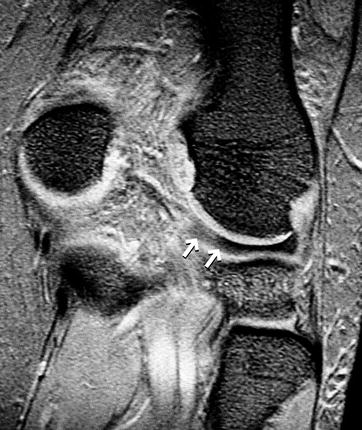
Fig. 2.7
Magic angle effect affecting the posterior horn of the lateral meniscus. Coronal T2*WI. Normal posterior horn of the lateral meniscus exhibits localized hyperintensity (arrows)
Magic angle effect can be avoided by using a long TE. Therefore, if magic angle effect is seen in T2*-weighted images, it can be eliminated by using SE sequences with a long TE or T2-weighted FSE sequences (Fig. 2.8).
Fig. 2.8
TE-dependent nature of the magic angle effect. T2*WI (GRE 560/14, flip angle 30°) (a) and T2WI (FSE 3,000/90) (b). Localized hyperintensity at the inferior aspect of the patellar tendon seen in (a, arrows) disappears if TE is made longer (b)
References
Erickson SJ, et al. The “magic angle effect”: background and clinical relevance. Radiology. 1993;188:23–5.Related posts:

Stay updated, free articles. Join our Telegram channel

Full access? Get Clinical Tree