Standard chest CT (‘combiscan’)
Scan mode
Helical
Indication
CVS anomalies
Strictures and small tracheobronchial stenoses
Peripheral airways disease
Tracheomalacia
Tumors and metastases
Congenital lung abnormalities
Anatomic coverage
Thoracic inlet to diaphragm
The upper abdomen is included if sequestration is suspected
Tube collimation
0.6 mm
Tube rotation
0.5 s
Slice reconstruction
1 mm
Pitch
1
Scan parameters
1–9 kg—80 kV, 60 QmAs, CTDIvol 0.88 mGy
10–15 kg—100 kV, 30 QmAs, CTDIvol 1.0 mGy
16–25 kg—100 kV, 38 QmAs, CTDIvol 1.26 mGy
26–35 kg—100 kV, 42 QmAs, CTDIvol 1.4 mGy
36–45 kg—100 kV, 48 QmAs, CTDIvol 1.6 mGy
Over 46 kg—100 kV, 55 QmAs, CTDIvol 1.83 mGy
Intravenous contrast
2 mls/kg (max 100 ml)
Scan delay of 20–30 s from start of injection depending on patient weight
Reconstruction kernels
B30f 1 mm (mediastinal window)
B60f 1 mm (lung window)
Tube current modulation
On
Table 2
Protocol: HRCT chest scanning parameters on a 64 slice system
HRCT | |
|---|---|
Scan mode | Sequential |
Scan parameter | 100 kVp |
1–25 kg—30 QmAs, CTDIvol 0.18 mGy | |
26–35 kg—35 QmAs, CTDIvol 0.21 mGy | |
36–50 kg—42 QmAs, CTDIvol 0.25 mGy | |
Over 50 kg—60 QmAs, CTDIvol 0.36 mGy | |
Tube rotation time | 0.5 s |
Tube collimation | 2 × 1 mm |
Table feed | Inspiration—10 mm |
Expiration—25–35 mm dependent on size of child | |
Coverage | Inspiration—apices to base of lungs |
Expiration—3 evenly spaced slices to cover upper/middle/lower lobes | |
Nonbreath-hold—2 slices each in R & L decubitus position | |
Tube current modulation | On |
Recon slice width | 1 mm |
Recon Kernel | 1st recon—B60 |
2nd recon—B30 | |
Window width/level | 1st recon—high-resolution lung parenchyma setting 2nd recon—mediastinum setting |
Contrast media | – |
Scan delay | – |
Table 3
Protocol: CT angiography scanning parameters on a 64 slice system
CT Angiography | |
|---|---|
Scan mode | Helical |
Scan parameter | 1–15 kg—80 kV, 60 QmAs, CTDIvol 0.88 mGy |
16–25 kg—100 kV, 30 QmAs, CTDIvol 1.0 mGy | |
26–35 kg—100 kV, 36 QmAs, CTDIvol 1.2 mGy | |
36–45 kg—100 kV, 45 QmAs, CTDIvol 1.5 mGy | |
46–55 kg—100 kV, 52 QmAs, CTDIvol 1.7 mGy | |
Over 56 kg—100 kV, 62 QmAs, CTDIvol 2.1 mGy | |
Tube rotation | 0.5 s |
Tube collimation | 64 × 0.6 mm |
Pitch | 1 |
Coverage | Dependent on indication |
Tube current modulation | On |
Recon slice width | 1 mm |
Recon Kernel | 1st recon—B30 |
2nd recon—B60 | |
Window width/level | 1st recon—medium soft, mediastinum |
2nd recon—high-resolution for lung parenchyma | |
Contrast media | 2 mL/kg to maximum 150 mL |
Scan delay | Bolus tracked—ROI outside body |
The axial images are reconstructed at 1 mm and archived to the PACS system within our hospitals. In recent years, we have made efforts to standardize low-dose protocols for the children scanned in our institution, and the currently applied parameters are summarized in the Tables 1, 2, 3, and 4.
Table 4
Dose comparison for different scanning protocols, based on actual patient data from GOSH
Effective dose per study (mSv) | |||||
|---|---|---|---|---|---|
Standard chest | HRCT | CTA | CXR | ||
<15 kg | 1.6 | 0.4 | 1 | 0.00487 | 0.00799 |
<25 kg | 1.5 | 0.4 | 1.9 | 0.00874 | 0.01086 |
<35 kg | 2.2 | 0.6 | 2.6 | 0.01163 | 0.00968 |
35–44 kg | 2.5 | 1.1 | 2.8 | 0.01769 | 0.01452 |
Methods adopted to minimize radiation dose in MDCT are multiple.
Automatic exposure control (AEC)
This system focuses on the average amount of noise per slice seen as acceptable and “fit for diagnostic purpose” by the user. The mAs is adjusted accordingly and can result in significant dose reduction (that is when the mAs can be reduced).
Automated tube current modulation systems have been produced by all of the major MDCT scanner manufacturers (Greess et al. 2004).
The tube current is modified to follow the anatomy of the patient, maintaining the same noise level within the images acquired.
Two methods are available, modulation in the x- and y-axes (angular modulation) and z-axis modulation.
Angular modulation adjusts the tube current, while the X-ray tube passes around the patient’s body, e.g., in an adult the mAs is reduced in the AP versus the lateral position. This is more beneficial in older patients who may be wider in the side to side, compared to anteroposterior directions, whereas baby’s bodies are more spherical.
Radiation dose reduction in CT examinations of children can be achieved by an attenuation-based on-line modulation of tube current (CARE dose) (Greess et al. 2002).
This z-axis current modulation needs the selection of an acceptable noise level and a maximum and minimum tube current, which are chosen before the examination. Thence, the scanner can adjust the tube current within the selected range and maintain the noise level, using data from the scout view or during gantry rotation. The reduction in tube current can be around 40 % using this technique (Karla et al. 2004).
However, the choice of tube current must be accurate prior to the examination as the automated dose control is set to preferentially overexpose to ensure good quality images and may in fact result in a dose increase (Gudjónsdóttir et al. 2010).
Reduction of the kilovoltage to 100 kVp when imaging the thorax
Further reduction to 80 kVp is possible for CT Angiography, but as resolution of the lung parenchyma is not always ideal (especially when looking for subtle patterns of interstitial lung disease) the 80 kVp option is applied only if lung pathology is unlikely and vascular anatomy is of paramount importance.
Iterative reconstruction
One of the most important advances in CT technique has been the development and utilization of new iterative reconstruction techniques which have resulted in a dramatic reduction in CT examination dose (Silva et al. 2010).
Iterative reconstruction techniques attempt to accurately rebuild images by focusing on noise reduction. One type of iterative reconstruction technique, Adaptive Statistical Iterative reconstruction (ASIR), uses information obtained from the Filtered Back Projection (FBP) algorithm as an initial building block for image reconstruction. The ASIR model then uses matrix algebra to transform the measured value of each pixel (y) to a new estimate of the pixel value (y′). This pixel value is then compared with the ideal value that the noise model predicts. The process is repeated in successive iterative steps until the final estimated and ideal pixel values ultimately converge.
Using this method, ASIR is able to selectively identify and then subtract noise from an image. Thus, ASIR reconstructs images with lower image noise compared with FBP.
When there are specific clinical indications, for example when high-contrast lesions are surrounded by low-contrast structures, dedicated low-dose protocols have been routinely used in the past in an effort to minimize radiation dose. For example, studies have suggested that low-dose CT is adequate for CT colonography (Cohnen et al. 2004), pulmonary CT angiography, and tracheobronchial evaluation (Heyer et al. 2007).
It is important to remember that although satisfactory for the dedicated evaluation of the intended specific anatomy, these protocols were implemented by knowing that image quality would be significantly reduced outside the immediate area of interest.
The application of the ASIR algorithm to these low-dose studies can significantly reduce image noise and improve overall image quality when compared with low-dose standard FBP techniques.
Pitch
Unlike the helical single-row scanner, an increase or decrease in table feed on the MDCT scanner only affects the overall scanning time when Automated Exposure Control is enabled. The tube current is automatically compensated to ensure that the present effective and total mAs is delivered. In other words, an increase in table speed triggers a concomitant increase in mA and this has no impact on the effective dose delivered.
Anatomical coverage for imaging of the pediatric thorax extends from the thoracic inlet to the diaphragm, but a greater degree of coverage may be warranted in certain clinical cases, such as an extralobar pulmonary sequestration, that may be present in the upper abdominal cavity.
In order to increase spatial resolution, the field of view (FOV) should closely approximate the cross-sectional area of the body part being studied. A large FOV would result in waste of matrix space and partial volume averaging would generate poor quality images (Callahan 1998).
Helical equipment is remarkably silent as compared to conventional scanners. For this reason, pediatric patients are not usually frightened and remain calm and still. This in itself reduces the need for sedation and improves image quality.
The quality of multiplanar reformatted images, MPR (coronal, sagittal, and curved) and 3D images is significantly improved with MDCT, which decreases motion-related artifacts and provides a smoothing effect of overlapped image reconstruction or due to the thin collimation of the new equipment, reducing stair-step artifacts. Such 3D images can be optimally rotated to display specific normal and abnormal structures allowing analysis of selected parts.
2.1.1 Limitations and Disadvantages of Helical CT Technique
The technical limitations previously associated with Helical CT technology have been rendered largely obsolete. The new generation of helical MDCT scanners provides a vast improvement in volume coverage speed with better resulting diagnostic image quality (Hu et al. 2000).
2.1.2 Pitfalls of Helical CT Technique
A common technical artifact associated with traditional helical data acquisition is the stair-step artifact (Wang and Vannier 1994). These occur along high-contrast interfaces that are oriented obliquely to the direction of patient travel. Stair casing causes the edges of longitudinally oriented structures to appear as steps rather than as straight lines. The thinner slice acquisition with MDCT scanners minimizes this technical artifact and image reconstructions are now very smooth and of very high-quality, the more detectors available the better the quality of the image.
Another potential pitfall with MDCT is related to commencing scanning before optimal organ or vessel enhancement by the contrast agent occurs in homogeneous fashion (Sillverman et al. 1995). These flow artifacts, caused by the mixing of contrast material and nonopacified blood are much more frequent in abdominal studies than in chest CT, in part because the circulation of blood is faster in the chest compared with abdominal blood circulation.
2.2 Personnel and Environment Requirements
The optimal team for performing pediatric MDCT includes a pediatric radiologist, a technician and a nurse trained in pediatric care. It is important to ensure an optimal environment for pediatric patients in the scanning area and every effort should be made to create a warm welcoming atmosphere that minimizes patient and parental anxiety. Soft lighting, toys, a quiet room decorated with children in mind, and the presence of a relative can help to comfort and console a child.
It is essential to have immediate access to a resuscitation cart with appropriate drugs and equipment for pediatric patients of all ages.
2.3 Previous Exam Evaluation
It is mandatory to check the patient’s clinical records and all available previous imaging studies before performing a helical CT scan. This helps to decide if the indication is correct and allows the exam to be tailored to the specific requirements of the patient. It is particularly important with regard to the need for sedation and IV contrast administration. Careful planning can prevent difficulties during the study and minimize the potential for unanswered questions afterward. The radiologist/radiographer should explain all aspects of the procedure and the objectives of the study to the parents before obtaining parental consent. At our institution, outpatients are contacted by the nursing team prior to the scan date to assess the needs of each patient, i.e., sedation requirements, etc.
2.4 Preparation of the Patient: Fasting Requirements
The patients, parents, and nursing staffs should be informed of fasting requirements before the day of the procedure. Sometimes, no preparation is required (e.g., when studying pulmonary metastasis). When children need sedation during the examination, standard fasting regimens are similar to those for a general anesthetic, water or breast milk can be given up to 2 h prior to sedation, and food up to 4 h beforehand.
2.5 Immobilization and Other Practical Tips
Sandbags, adhesive bandages, or blankets wrapped around the patient can all be used to immobilize the patient. It is advisable to wrap a lead apron around the child in the regions adjacent to those to be scanned. This protects them from scattered radiation and, at the same time, can help to immobilize the patient. Overlying radio protective bismuth latex can be placed on breasts and thyroid gland to minimize local radiation absorption to these radiosensitive tissues. However, it should be noted that the use of these devices can increase the overall mAs with some scanners if automatic dose modulation is used and therefore increase overall dose. There is evidence to suggest that performing an initial scout view without shielding prevents the scanner increasing the dose (Coursey et al. 2008).
Toys hanging from the gantry and films or image projection on the gantry can be used to attract the attention of the child and help to keep them quiet. A system for maintaining body temperature such as warming lamps or heating blankets should be used in infants.
2.6 Breath-Holding Information
Children under 6 years of age who cannot follow breath-holding commands are examined under normal quiet breathing. In this age group, attempts at breath holding usually result in exams severely compromised by artifacts. Older children are carefully instructed in breath holding before the study.
2.7 Sedation
Helical CT and MDCT have reduced the need for sedation (White 1995; Kaste et al. 1997; Sacchetti et al. 2005). Since the introduction of silent helical CT and high-speed MDCT in our institutions, our overall rate of sedation is only 1 % of patients for MDCT versus 18 % for our previous conventional CT studies. In 2012, using new generation CT equipments, we performed only 1 % of our thoracic CT studies with sedation.
Previously, in patients under the age of 6 years, 50 % required sedation with conventional CT and only 8 % with helical CT and 2 % with MDCT. Among the patients in this age group who needed IV contrast, 77 % had to be sedated with conventional CT, only 18 % with single slice helical CT and 3 % with MDCT. Finally, among those who did not need IV contrast material, 24 % required sedation with conventional CT, only 2 % with helical CT and 1 % with MDCT. We believe that the relative silence of the helical equipment and the high speed of acquisition have determined this reduced need for sedation. It has been widely reported that with multidetector CT the rate of sedation can be reduced (Pappas et al. 2000).
In outpatients, the need for sedation is assessed by the clinician prior to the investigation and by a dedicated nursing sedation team who telephone the parents prior to admission. A standardized questionnaire is used to evaluate the need for potential sedation.
Despite this, there will still be a need for a final sedation assessment once inside the gantry.
In our experience, infants less than 3 months of age can be successfully imaged after normal feeding and swaddling. Sleep deprivation, the night before the examination has proven to be of no benefit in either decreasing the dose of sedative drugs, or the number of sedation procedures, and can be disruptive for patients and parents.
Before performing an examination with the use of sedation, the radiologist must decide whether benefits outweigh the potential associated risks, and verify that fasting requirements have been observed. In our institution, informed consent for sedation is covered by the standard consent for admission and CT scan examination.
There are several contraindications to the use of sedation at our institution. These include: raised intracranial pressure, airway obstruction, gastroesophageal reflux with aspiration risk, and severe renal/hepatic failure.
We do not sedate children under 45 weeks gestation, and a “feed and wrap” protocol is usually sufficient at this age.
In children older than 45 weeks gestation but under 15 kgs we use oral Chloral Hydrate at a dose of 50 mg/kg (to a maximum dose 2000 mg).
When using this regimen and if IV contrast injection is contemplated, the intravenous line is placed in the preparation room before the patient is brought to the CT unit.
In our hospital in Spain, patients of 18 months of age and older, who need sedation, are given intravenous sodium pentobarbital, 6 mg/kg to a maximum dose of 200 mg, diluted in 10 ml saline. The syringe containing the sedation must be appropriately labeled with the drug name. A dose of 2–3 mg/kg should be given initially as slow bolus over 1–2 min. In most children, this dose is adequate and they will fall asleep within the next 4–5 min. If not, an additional dose of 2–3 mg/kg may be given. If the patient still remains awake an additional dose of 2 mg/kg can be given some 30 min later. However, this is rarely necessary. Occasionally, in some patients over 6 months of age who need IV contrast, sodium pentobarbital in the above-mentioned doses is used.
Sedation Protocol GOSH: (February 2012): Great Ormond Street Hospital for Children, London UK.
<45 weeks gestation—Feed and wrap only. No sedation.
>45 weeks gestation but <15 kgs—50 mg/kg Oral Chloral Hydrate.
Intravenous “top ups”
If the sedation is not effective, supplementary sedation may only be given by a doctor who is skilled in pediatric resuscitation according to the anesthesiologists practice and expertise, which will vary locally.
Intravenous midazolam is used at incremental doses of 100 μg/kg in children under 20 kgs. The dose must not exceed 300 μg/kg or 10 mg.
NB sedation will sometimes fail and these doses must not be exceeded.
If sedation fails, an anesthesia service must be booked for another day.
Every child undergoing sedation in the CT suite should receive oxygen and be monitored during and after the examination.
2.8 Intravenous Contrast Material Administration
Intravenous administration of a bolus of contrast material for helical CT studies in children can be more complicated than in adults, because of the greater variations in vessel and patient size in the pediatric population. Dosage is based on the patient’s body weight. Contrast material is administered by hand or power injector, depending on these variations (Kaste and Young 1996; Frush et al. 1997). To avoid the artifact caused by contrast in the axillary vein just after the injection, the syringe is placed vertically downward and filled with contrast first and then saline solution. Since saline is less dense than contrast material, it will remain in the syringe until the end of the injection and then flush the vein free of contrast. This will help to obtain better images (Hopper et al. 2000).
Newer power injectors have a double system of syringes, one syringe for contrast material, and a second syringe for saline solution.
Usually, the double power injector is programmed to inject the contrast material first followed by 5–10 cc of saline solution. It is necessary to check that the venous line is functioning prior to contrast media injection to prevent extravasation occurring.
If contrast material is to be given, an intravenous catheter or a butterfly needle should be placed before the child arrives in the CT suite. This will avoid the distress associated with venepuncture performed immediately before scanning begins, and help to reduce the need for sedation. Local topical analgesics, such as lidocaine cream, can be applied to the intended venepuncture site to minimize the pain from cannula placement.
Usually, we use catheters 20–26 Gauge, permitting injection rates of 4.0–1.0 ml/s. Butterfly needles 19–25 Gauge, which give injection rates of 4.0–0.5 ml/s can also be used. (Tables 5 and 6).
Table 5
Protocol: Suggested delay times from the injection of contrast medium
Manual injection | Pressure injector | |
|---|---|---|
Scan initiation time delay | Immediately from termination of injection | 20–30 s from start of injection. If a central line is used, this time will be reduced. Bolus tracked studies are operator dependent |
Flow rate | 1.5–2 ml/s | |
Age range | All age groups | All age groups |
Table 6
Protocol: Rate of contrast media injection depending on catheter or needle gauge
Catheter/Cannula | Needle | ||
|---|---|---|---|
Gauge (g) | Flow rate (ml/s) | Gauge (g) | Flow rate (ml/s) |
26 | 1.0 | 25 | 0.5 |
24 | 2.0 | 23 | 0.5–0.8 |
22 | 3.0 | 21 | 0.8–2.0 |
20 | 4.0 | 19 | 2.0–4.0 |
One should always use the largest cannula suitable for each patient, though rates as low as 0.5–1.0 ml/s in children can still result in excellent enhanced studies. If the patient already has a central intravenous line in situ, it should be used to gain venous access, using aseptic technique.
Nonionic, low- (240 mg of iodine per milliliter), or high- (300 mg of iodine per milliliter) osmolar contrast media can be used for CT examinations in children (Stokberger et al. 1998). In our practice, we use 240 mg/ml in infants and 300 mg/ml in older children.
The usual dose of contrast media is 1–3 ml/kg, to a maximum dose of 100 ml. In newborns the dose used is 2–3 ml/kg, in infants 2 ml/kg, in children 1.5 ml/kg, and in adolescents 1 ml/kg.
In our experience, helical CT has allowed a 20 % reduction in the volume of intravenous contrast medium given when compared to conventional CT. Similar findings have been described in the literature (Costello et al. 1992a). Optimal contrast enhancement during helical scanning depends on careful selection of the appropriate time of scanning, as well as on choosing the precise amount of contrast material and the optimal injection rate. The rate of injection depends on the needle or catheter size (Table 6). The timing of the onset of scanning is a crucial factor in successful imaging, but is also one of the trickiest aspects of performing pediatric helical CT.
2.9 Technical Parameters and Protocols
Helical CT has essentially replaced conventional CT for examinations in which the entire chest is to be evaluated. A role for low-dose high-resolution sequential CT remains with the evaluation of the pulmonary parenchyma in cases of suspected diffuse lung disease (Garcia-Peña et al. 2011).
This technique allows scanning at spaced intervals and thus significantly reduces radiation to the patient, while providing excellent spatial and contract resolution of the lung parenchyma.
In our institutions, we tend to use the sequential HRCT studies in the follow-up assessment of children with chronic lung disease such as cystic fibrosis and interstitial pneumonia (Ambrosino et al. 1994; Lucaya et al. 2000b; Garcia-Peña and Lucaya 2004).
Several techniques are used for data acquisition in helical studies of the chest: standard helical CT, high-resolution helical CT, dynamic helical CT, and low-dose helical CT.
With newer MDCT scanners with multiple detector banks (64 slice +) the narrow collimation (0.6 mm) allows for a study to be performed, of high enough contrast and spatial resolution to allow optimal imaging for both mediastinal and lung parenchymal anatomy without the dose penalty that is incurred with older MDCT scanners.
The modern scanner and the dose reduction methods described above have reduced the dose of this protocol, to such a level that the value in terms of high quality parenchymal and mediastinal imaging in a single study, far outweighs the negligible increase in dose compared to the thicker collimated studies previously performed. We term this a “combiscan.”
This protocol (Table 1) has largely replaced the ‘routine chest protocol’ at our institution for most indications. This study has particular value in the assessment of vascular anomalies, tracheobronchial stenosis, dehiscence, endobronchial lesions, and central airway disease. The thinner collimation allows for excellent Multiplanar and 3D reconstructions. These can be useful in the evaluation of airway abnormalities, certain vascular lesions and cervico-thoracic or diaphragmatic and peri-diaphragmatic lesions. 3D images can be rotated to optimally display pathologic entities and selected parts of the reconstruction that can then be analyzed separately.
Helical high-resolution CT scanning of the lung is performed with thin sections (0.5–1 mm) using a high-resolution reconstruction algorithm. This technique is similar to high-resolution CT scanning, but involves continuous data acquisition (Engeler et al. 1994). Lowering the milliamperage setting reduces radiation dose, but the continuous data acquisition of helical CT still delivers more radiation than the low-dose interval high-resolution CT technique (Table 2), in which acquisition is performed with thin collimation and wide sampling intervals.
Dynamic helical CT has enabled scanning at maximum inspiration (TLC, i.e., total lung capacity) and rescanning with an additional spiral acquisition at maximum expiration. This volumetric expiratory method has been used to evaluate lung attenuation in patients with air trapping and emphysema. However, it requires cooperation with breath holding at end expiration, and in young patients <5 years breath holding is problematic.
In our practice, we do not use this technique routinely to evaluate air trapping and emphysema.
We prefer three spaced expiratory scans with a low-dose high-resolution technique (Lucaya et al. 2000a). In a non-cooperative child, 2 decubitus slices with the child lying on both sides, i.e., 2 in the right, and 2 in left decubitus positions, shows expiration in the dependent lung (Papaioannou et al. 2007).
Minimum Intensity Projections (MinIP) reconstructions of standard volume acquisitions are also an excellent method for the evaluation of heterogeneous lung parenchymal attenuation where the hyperlucent lung is a reflection of air trapping.
Software programs (available on some helical scanners) have enabled dynamic CT densitometry of the lungs (Johnson et al. 1998b). Dynamic helical CT can also be used to demonstrate respiratory changes in the cross-sectional area of the central airway, e.g., in patients with tracheobronchomalacia (Lee et al. 2009). Dynamic airway assessment may also be achieved with newer techniques such as cine MDCT and four-dimensional (4D) MDCT (Lee et al. 2010b, 2013).
Dynamic CT has been used in adults in the preoperative assessment of tracheomalacia, but the high-radiation dose has previously limited its use in children. However, the advent of 320 slice scanners allows the whole thorax to be scanned in a single tube rotation or less. The effective doses for these studies have been shown to be reduced in comparison to scanners with less coverage (Lee et al. 2009, 2010a; Joosten et al. 2012).
Low-dose helical CT scanning can be used in many situations. The X-ray tube current should be as low as possible, without compromising image quality (Takahashi et al. 1998; Rogalla et al. 1999). With helical CT technique, a further reduction in radiation dose can be achieved by increasing table speed if automated dose modulation is not available or not enabled. Use of a targeted approach to image localized processes can also reduce the radiation dose administered.
The performance of high-quality helical CT requires proper selection of technical parameters, including collimation (section thickness), field of view (FOV), table speed (or pitch), reconstruction intervals, reconstruction algorithms, scan time duration, exposure factors (kilovoltage and milliamperage), and scan initiation (Brink 1995; Frush and Donnelly 1998; Frush et al. 2002). These parameters should be based on the patient’s size and the body part to be examined. However, reduction in some of these parameters can lead to problems. Noise increases with decreasing collimation. Scan coverage decreases with reductions in collimation and table speed. Radiation dose increases with reductions in table speed and with reduction in collimation. Decreasing the reconstruction intervals increases processing time.
So, the final choice of parameters always involves a balance between these options to achieve diagnostic image resolution and a low effective dose to the patient.
MDCT scanners have subsecond gantry rotation times. So, reducing rotation time from 1 to 0.5 s, we will halve the radiation dose and the scan time if the mA is fixed (i.e., ADM is not enabled).
The kVp has not routinely been adjusted historically for body CT exams in children. Reducing the kVp reduces the radiation dose substantially, that is in an exponential fashion. In our experience, when the voltage is dropped from 120 down to 80, the radiation dose is decreased by 40 %.
The effect on image quality is important, as both image noise and tissue contrast are affected. The kVp can be reduced (to 80 or 100), related to the child’s size or when scanning body regions with high inherent contrast such as the chest, airways, and in skeletal studies and CT angiography (Heyer et al. 2007).
The number of detector rows can also affect effective dose via radiation exposure. MDCT scanners have an inherent dose problem in relation to the X-ray beam, which extends beyond the confines of the detector rows (over-scanning). This effect decreases with more detector rows.
In modern scanners, the X-ray beam is filtered, contouring its shape very closely to remove photons that otherwise will be absorbed by the patient, thus decreasing the radiation dose to the patient.
This process is known as z-axis collimation and is most effective over short scan distances and with greater pitch. This is obviously of particular relevance in pediatrics (Christner et al. 2010).
Post-processing techniques using noise reduction filters can allow the use of low mAs (lowering effective dose) and thus improve the quality of the images for diagnostic purposes (Kalra et al. 2003).
Nowadays, most of the MDCT scanner manufacturers make efforts to help with radiation dose control. They have made changes in their equipment to give information on dose and on how to use modulation dose systems to maintain image quality. They have produced age and (much more appropriately) size/diameter adjusted protocols, which are useful as a guide for pediatric dose reduction.
The image reconstruction interval is usually set at an interval equal to the collimation. If multiplanar or 3D reconstructions are required, reconstruction with 50 % overlap can be performed for better definition. Moreover, overlapping images increase lesion depiction, which is useful in the evaluation of small pulmonary nodules.
The raw volumetric data is currently reconstructed using an algorithm based on filtered back projection. This algorithm is not able to consistently produce diagnostic quality images with low mAs (i.e., low-dose examinations) as the background noise produced is excessive. The more recent algorithm for noise reduction in low dose studies has been discussed above, i.e., adaptive statistical iterative reconstruction (ASIR).
ASIR uses a series of statistical models to reduce image noise and produce studies with dose savings in excess of 30 % (Silva et al. 2010; Yanagawa et al. 2010).
The most frequent reconstruction algorithm used is the low-spatial frequency (standard) algorithm. As routine in our institution, the pulmonary parenchyma is analyzed with a high-spatial frequency algorithm (bone algorithm).
Scan duration should be tailored as much as possible to the breath-holding ability of the child. The scan delay time varies with the region of interest and the clinical indication of the study (Table 1). The scan delay time for CT angiography (Table 3) is more complex and will be the arterial time, obtained by monitoring the contrast enhancement in the descending aorta. This is done by acquiring very low mA scans at the same level (one scan every 3 s over 15 s) and determining the time of peak contrast when the spiral data acquisition should be commenced.
Alternatively, an automated bolus-tracking technique can be used to monitor contrast enhancement and initiate scanning. Scanning begins once an arbitrary threshold level of contrast enhancement is reached within a predefined region of interest (ROI chosen as 100 HU in our institutions). There are limitations with this technique if the scanner protocol is not adjusted for the relatively high heart rates of children. This can result in optimal contrast enhancement being missed due to erroneous (delayed) scan initiation.
2.10 Image Postprocessing
Standard post-processing techniques include four reconstruction displays: Multiplanar Reformats or reconstructions (MPRs), 3D Shaded-Surface-Displays (SSDs), Multiprojective Volume Reconstructions (MPVRs), and 3D Volume Renderings (VRs) (Fig. 1).
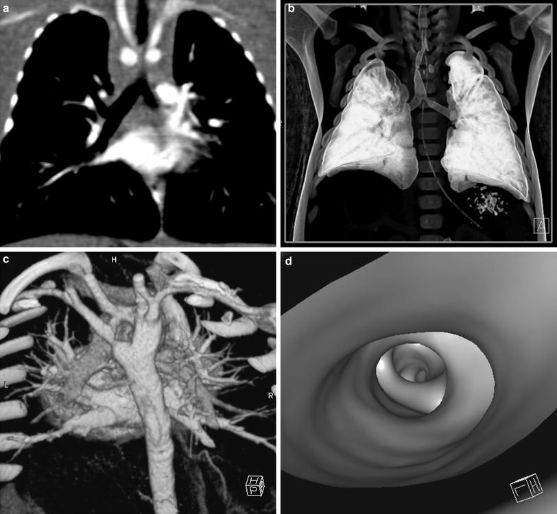
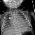
Fig. 1
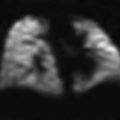
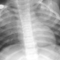
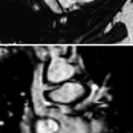
Post-processing techniques. a Multi-planar reformats (MPR). MPR initially in coronal and sagittal planes should be the initial post-processing technique: with pixel isotropy, no information is lost, and the reformatted plane often gives a better depiction of the anatomical relationships. The coronal image shows a double aortic arch and its effect on the airway. b Multiplanar volume reconstructions (MPVRs). MPVRs combine volume rendered images with multi-planar imaging to produce 3D ‘slabs’ of the area of interest. By applying a minimal intensity projection technique a view of the airways can be produced such as this example of a congenital tracheal and left main bronchial stenosis in a 3-year-old boy with bronchiolitis. This technique is sometimes referred to as a “virtual bronchogram”. Historic stair-step artefact in traditional single slice volume-rendered image (bronchographic anteroposterior view). The artefact occurs along the left bronchus, which is oriented obliquely to the direction of patient travel during data acquisition. c Three-dimensional (3D) volume rendering (VR) is an excellent technique for giving an overview of complex vascular anatomy. This example, image weighted on SSD technique is a posterior view of the great vessels with the spine and posterior ribs ‘cut-away’, showing a double aortic arch with a dominant right arch. d Virtual bronchoscopy is a supplementary volume rendering technique that produces images simulating the view from fibreoptic bronchoscopy. The point of view is placed in the airway. This example demonstrates complete tracheal rings in congenital tracheal stenosis: note the abnormally rounded shape to the airway, which is normally ovoid
The axial images include all the information about the anatomy that is provided with 2D and 3D reformats and it is this information that should be used for most diagnostic purposes. However, postprocessing gives added value to imaging when analyzing oblique structures as well as interfaces and surfaces parallel to the axial plane which are poorly demonstrated and sometimes occult on standard views. 2D and 3D reconstructions are also useful for display of pertinent findings to clinicians and for preoperative planning.
Multiplanar Reformations (MPRs) (Fig. 1a) provide additional diagnostic information in different planes and are as accurate as the axial scans because the data is acquired iso-volumetrically. MPRs are 1-voxel-thick, 2D tomographic sections that can be displayed in standard coronal and sagittal planes, but can in fact be reconstructed in any plane required or in a single tomographic “curved” plane, along the axis of a structure of interest, e.g., a bronchus or a feeding vessel (Salvolini et al. 2000; Siegel 2003). They are real-time, easy-to-reconstruct images, producible as soon as the axial sections are completed. They generally improve our perception of images and give information that although contained in transverse images, is less effectively displayed. Their diagnostic value is substantial in demonstrating and documenting the presence of small focal lesions, defining the vertical extent of a bronchial stenosis, which may go undiagnosed from the axial source CT images, and are invaluable prior to surgical remodeling of vascular rings and the tracheobronchial tree. However, to avoid misinterpretations due to partial volume effect, e.g., overestimation of the degree of a stenosis, overlapping and thinner cuts should be applied when processing the raw data. Likewise, when processing curved MPRs, the trace should be centered within the lumen of interest to avoid anatomic distortion.
Three-dimensional (3D) imaging is a diagnostic tool necessary only in certain cases as it usually requires more time and post-processing skills to provide information already included and demonstrated in the axial images and the MPRs. There is no doubt however that the 3D reformatted images may further increase the diagnostic confidence.
Shaded-Surface-Display 3D Techniques (SSDs) (Figs. 1c, 2c) are applied in the imaging of the central airways, vessels, and bone structures and they are usually more visually impressive than clinically useful.
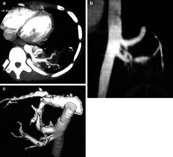
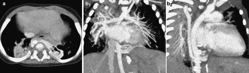
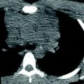
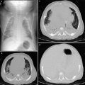
Fig. 2
CT angiography of a pulmonary sequestration in a 6-year-old boy who was asymptomatic, but had a persistent dense image in the left pulmonary base. a Axial CT image. A large vessel is seen arising from the aorta, with multiple branches supplying a pulmonary mass. b Anterioposterior maximum intensity projection image. Three systemic vessels coming from the aorta are seen to feed the pulmonary sequestration. c Posteroanterior shaded surface display (SSD) image. The 3D depth perception created by SSD technique improves recognition of spatial relationships of the three vessels arising from the aorta. Two veins are also shown in the upper area of the image. With a cine-loop rotating image, the origin and the course of vessels can be better depicted
SSD generates images with depth and 3D information. Using binary classification, voxels with attenuation values above a preset threshold are set to white and voxels with lower attenuation values are set to black (Brink 1995). This method first computes a mathematical model of a surface that connects neighboring pixels with CT intensities above a preset threshold.
Depth or 3D perception is created by shading techniques using an imaginary light source that can be arbitrarily positioned. Such data can be then rotated, allowing the image to be viewed from any perspective.
Their generation from original data is time-consuming and they carry the risk of loss of density information due to problems with thresholding. The threshold must be carefully chosen and should be based on the intensity of the contrast material in the area of interest. The choice of threshold will strongly affect the evaluation of some lesions, such as the degree of stenosis. Choosing too low a threshold may increase noise and also allow the higher density soft tissue to obscure the target vasculature. Choosing a too high threshold may result in small vessels disappearing and/or stenoses being falsely implied.
Another problem encountered with SSD is that the reduction of CT volume data to a single surface removes the inherent CT quantitative density values, losing gray-scale levels. With this threshold technique one cannot differentiate between solid organ intraparenchymal vasculature and enhancing parenchyma, or between high attenuation structures in vessel walls and intraluminal contrast enhancement.
Multiplanar Volume Reconstructions (MPVR) (Fig. 1b) allow a combination of the spatial resolution of thin sections with the anatomical display of thicker slices and all the information acquired in the raw data set is used. The routine CT images are combined in multiples to create an image thicker in voxels, the volume “slab”, which constitutes an interactive sum of axial, coronal, and sagittal reconstructed sections (Siegel 2003; Salvolini et al. 2000). By using different algorithms and setting thresholds, maximum (MIP) or minimum intensity (MiniP) voxels can be highlighted within the slab (STS-MIP, STS-MinIP). The sections are typically thin 2–3 mm sections rendered into approximately 20–30 mm slabs (Napel and Jeffrey 1993).
Maximum Intensity Projections (MIP, STS-MIP) Images are generated by mapping the maximum attenuation value along each ray to produce a gray-scale image. Thus, bone and calcified structures are bright and are distinguishable from both iodinated contrast material and soft tissue. In a vascular examination, it will be necessary to postprocess the image to avoid bone images (Brink 1995).
MIP images are useful for displaying vascular structures, for CT angiography, and for separate parenchymal nodules from surrounding pulmonary vasculature. They reliably display vessel caliber, metallic stents, and wall calcifications, but provide poor separation of overlapping vessels because 3D relationships are lost (Fig. 2). Vascular anatomy is frequently difficult to comprehend from standard cross-sectional images. Blood vessels that are perpendicular or oblique to the section will appear as small circles or ellipses, and may mimic the appearance of a pulmonary nodule. With MIP, one can integrate the path of vessels and their connections with other structures into the larger picture of vascular anatomy (Fig. 3).