Fig. 1
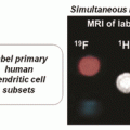
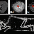
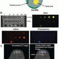
MPI for high-contrast tracer imaging . (a) MPI scans with/CT overlay of two SPIO vials (at 1 and 2.8 mm deep) shows no signal change with depth. (b) Fluorescent scan of two implanted fluorescent probes at the same depths as (a) shows a dramatic signal loss with depth. (c) MRI (7T T2*) images of two SPIO vials from (a). SPIOs induce areas with loss of signal, which are difficult to distinguish from naturally dark tissues such as air in the lungs or tendons. (d) MPI/CT overlay of IV injected stem cells trapped in the lungs on day 1, (e) with redistribution to and clearance from the liver on day 12
Unlike other techniques, MPI directly images the magnetization of SPIO tracers , so the MPI signal is not affected by any biological tissue. No biological tissue contains a magnetic signature similar to that of SPIOs, and hence there is no tissue background signal in MPI, akin to nuclear medicine techniques and fluorine MRI. Moreover, the low-frequency magnetic fields used in MPI are completely transparent through biological tissue, enabling imaging of deep anatomic structures. These properties, combined with the linear quantitation in MPI for SPIO tracers and the safety of both the SPIO tracer and the nonionizing MPI scanning technique, make MPI ideal for a variety of sensitive clinical molecular imaging applications.
2 Introduction to Magnetic Particle Imaging
MPI was originally developed by Bernhard Gleich and Juergen Weizenecker at Philips Research in Hamburg [2]. The field of MPI research is rapidly expanding, and current efforts in MPI development are in progress both in industry at Philips research [2–6], Bruker [7], Lodespin Labs [8, 9], and Magnetic Insight [10], as well as in academia at UC Berkeley [11–22], University of Lubeck [23–25], Bilkent University [26], Physikalisch-Technische Bundesanstalt and Charité-Universitätsmedizin Berlin [27, 28], TU Braunschweig [29, 30], University of Wuerzburg [31], Osaka University [32, 33], University of Washington [9, 34–39], Harvard Massachusetts General Hospital, Case Western Reserve University [40], Johns Hopkins University [41], University of Twente [42, 43], Dartmouth University [44, 45], and TU Hamburg-Harburg [46, 47], among many others.
Since its development, MPI has shown promise for a variety of medical imaging applications, such as angiography and blood pool imaging [2–4, 11, 14–16, 21], cancer imaging [16], perfusion imaging, and stem cell tracking [13, 20, 41]. In MPI, we use SPIO tracers (also used in T2*-MRI), but MPI scans cannot be obtained with an MRI scanner; the MPI hardware is completely distinct .
2.1 MPI Trade-Offs
MPI visualizes SPIO tracers by direct induction, so the MPI signal scales exactly linearly with the number of SPIOs in the imaging volume, meaning MPI is a “hotspot” imaging technique without background signal, similar to nuclear medicine techniques. For stem cell tracking , MPI provides quantitative cell counts anywhere in the body for up to months in the same animal [13]. Unlike optical imaging, ultrasound, X-ray, and other imaging methods, the MPI magnetic signal suffers zero attenuation with depth and there is no MPI signal from background tissues. The MPI signal also has excellent mass sensitivity because MPI detects the intense electronic magnetization of an SPIO, which is 22 million times more intense than the nuclear paramagnetism of water in 7T MRI. Hence, our prototype MPI scanner can detect even 2 nanograms of SPIOs within a single voxel. Theoretically, this translates to roughly 200 nanomolar concentration of iron, or to 200 cells with in vivo scans in state-of-the-art MPI scanners. Hence, the contrast and sensitivity of MPI rival nuclear medicine techniques like PET and SPECT without concerns about radiation dose or “half-life” constraints. Indeed, a few SPIO formulations have previously been approved by EU and FDA as diagnostic agents. MPI uses no ionizing radiation, and it can operate within the human magnetic safety limits so human translation will soon be feasible. Current disadvantages of MPI include relatively poor spatial resolution (roughly 1 mm in a mouse), and the lack of anatomical information implying that it cannot be used as a single imaging modality alone. Recently, a commercial murine MPI scanner was released in Germany (Bruker), and a preclinical scanner is in development at Magnetic Insight (California). A start-up in Seattle (LodeSpin Labs ) has been formed around the synthesis of MPI-tailored SPIOs.
2.2 How MPI Works
The physics governing MPI is completely different from MRI, and it is not possible to perform MPI with an MRI scanner or vice versa. An overview of the physics, hardware, and reconstruction theory of MPI can be found in references [2–4, 11, 12, 14–17, 21, 48]. The SPIO tracers used in MPI obey steady-state Langevin physics as shown in Fig. 2. They achieve steady-state alignment shown here with applied fields in tens of microseconds. MPI scanners employ a strong gradient field to force all SPIOs outside of the gradient field origin, called the field-free point (FFP) , to be saturated. Saturated SPIOs induce no signal in the MPI inductive receiver coil because they are static.


Fig. 2
Langevin theory describes the steady-state magnetization of an ensemble of SPIOs. (Top) SPIOs magnetize and quickly fully align, or saturate, in the presence of applied magnetic fields. (Bottom) We observe the SPIO density after it is blurred (or convolved) with the MPI point spread function (PSF), which is the derivative of the Langevin function
All MPI scanners today scan the FFP across the FOV at roughly 25 kHz to create an MP image, as illustrated in Fig. 3. The SPIOs flip their orientation when the FFP sweeps past their location. The flip of even 2 nanograms of SPIOs in a voxel induces a detectable signal in a receiver coil. Importantly, the induced signal is linearly proportional to the SPIO mass at each location in space. Hence, the time axis of the MPI induction signal maps directly to spatial location in the SPIO image. This is the intuition behind the x-space MPI reconstruction algorithm [11, 12, 14–17, 48]. Multidimensional MPI is a simple extension of the 1D imaging process. Movement of the FFP in 3D is implemented by dynamically driving three spatially homogeneous “slow shift field” coils, one aligned with each direction (x, y, z). This effectively scans the FFP, or field-free line (FFL) , in two or three dimensions, as shown in Fig. 4.


Fig. 3
In MPI, we raster a gradient field across the field of view, typically at 25 kHz. This is illustrated here in 1D but the principle is the same in multiple dimensions. Any SPIOs near the instantaneous FFP (or FFL) are flipped, inducing a voltage in the pickup coil that is linearly proportional to the mass of SPIOs at the FFP (or FFL) location. This allows for fast and robust x-space image reconstruction

Fig. 4
Illustration of our prototype FFL scanner and 2D MPI scanning process. Three superposed magnets (field-shifting magnets, gradient magnets, and transmit magnet) produce and translate a magnetic field-free line (FFL) across an imaging volume. As the FFL is rastered across a distribution of SPIO particles using a spatial imaging trajectory, the particle ensemble magnetization changes in magnitude and orientation in response. The changing particle magnetization is detected via a detector coil and reconstructed to form an image
2.3 The Direct Feed-Through Challenge
Unfortunately, all MPI scanners must deal with a crucial technical challenge. The received MPI signal occurs at the same time as the drive field, which can be orders of magnitude stronger in amplitude. Hence, the receive coil picks up a massive interference from the time-varying drive fields. Fortunately, this direct feed-through interference is localized (mostly) at the drive frequency, typically 25 kHz, by meticulous design of the transmit power electronics to ensure a low total harmonic distortion at 10–100 ppm. Hence, while the MPI signal is not contaminated by direct feed-through at higher harmonics, the signal at the fundamental frequency is swamped with direct feed-through interference. As a result, all MPI scanners reject the direct feed-through using a sharp passive filter, with more than 30,000-fold suppression. Unfortunately, this filter also removes the first harmonic content of the SPIO signal. The MPI image reconstruction challenge is to reconstruct a high-quality SPIO image using only the SPIO signal derived from higher harmonics of the 25 kHz drive frequency.
Both the system matrix reconstruction approach, advanced by Philips, and the x-space reconstruction approach, developed by UC Berkeley, have shown that the lost first harmonic information corresponded precisely to the average (baseline or DC) signal in a partial imaging volume [4, 11]. Hence, it is possible to design a robust image reconstruction algorithm that restores the lost DC information using excitation trajectories with overlapping partial imaging volumes, or field of views (pFOV). These are then stitched together using a fast continuity algorithm [11], which is demonstrated in Fig. 5. Importantly, Lu et al. and Zheng et al. proved experimentally and theoretically that MPI is a linear and shift invariant imaging system after the lost baseline information is restored [11, 13]. Several studies have also proven that the fundamental 1D point spread function (PSF) of MPI is simply a scaled version of the derivative of the SPIO’s Langevin function, as shown in Fig. 2 [14, 15, 17]. Below we summarize the fundamental properties of MP images: contrast, sensitivity, and resolution.


Fig. 5
Illustration of the x-space MPI DC recovery algorithm [11]. Overlapping partial FOVs lose all local baseline information due to the direct feed-through rejection filter. Using the a priori information that the MPI distribution is smooth, this continuity algorithm recovers the lost information to reconstruct a smooth 1D image
2.4 MPI Signal Is Independent of Depth
Unlike in optical or ultrasound imaging, biological tissue does not attenuate the MPI signal. There is also no signal from living tissue in MPI as demonstrated experimentally in Fig. 6. This makes MPI uniquely suitable for linearly quantitative and radiation-free cell tracking at any depth in vivo.


Fig. 6
MPI scans of a helical phantom (left) and a helical phantom embedded in animal tissue (right). This comparison makes clear that tissue creates no MPI signal and does not attenuate the image
2.5 MPI Sensitivity Is Linear, Robust, and Ideal
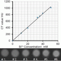
As shown in Fig. 7, the MPI image intensity signal scales linearly with the mass of SPIO particles at each pixel due to the linearity and shift invariance properties of MPI. Therefore, the MPI signal is perfectly linear and quantitative with cell count. MPI directly detects the SPIO electronic magnetization, which is 22 million times more intense than the nuclear paramagnetism imaged in 7 T high-field MRI. Direct detection of SPIO tracers enables “hotspot imaging” in MPI as opposed to the “negative contrast” when the same SPIOs are used in T2*-MRI. We have experimentally demonstrated a linear detection limit of 200 labeled cells in vitro [13], with potential for significant further improvement. This linear sensitivity is superior to all other imaging modalities, the detection limits of which are compared in [1].


Fig. 7
(Left) Graph of MPI signal vs. number of labeled hESC-derived cells. The MPI signal is linear and quantitative (R 2 = 0.994). (Right) MPI of phantom of six SPIO-labeled cell populations ranging from 0.4 million to 1.6 million cells, with full image intensity scale at 2.4 μg Fe/mm2 corresponding to the 1.6 million cell pellet
Importantly, although SPIOs respond nonlinearly to the applied magnetic field, the MPI signal induced from the rotating SPIOs in the receiver coil is perfectly linear with respect to the mass of SPIOs. Hence, there is absolutely no saturation of the MPI signal at higher cell counts. The details of the linearity and shift invariance of MPI are shown in [11, 14].
2.6 MPI Resolution
The fundamental spatial resolution of MPI depends only on the saturation characteristics of the SPIO particles and the strength of the magnetic gradient. Doubling the gradient strength improves resolution by twofold in every dimension. Currently available SPIOs saturate at roughly plus or minus 3 mT, which translates to a spatial resolution of roughly 1 mm in a 6T/m gradient field. While this resolution is comparable to preclinical nuclear medicine, it is not yet competitive with CT or MRI small-animal imaging. To improve MPI’s spatial resolution we and others have studied SPIOs with varying core diameters, since Langevin physics predicts a cubic resolution improvement with increasing SPIO core size. This has produced exciting results effectively reducing the FWHM resolution by a factor of two over Resovist [8]. Unfortunately, researchers have noted that improvements beyond roughly 25 nm core diameter seem to be limited, perhaps due to relaxation-induced blurring [18, 19]. This area remains a major active research area for tailoring nanoparticles to improve MPI performance.
2.7 Prototype Preclinical MPI Scanners
All of the imaging data shown in this chapter are obtained from the two scanners shown in Fig. 8. The top shows our 2.4,T/m FFL scanner , which allowed us to perform fast projection imaging as well as 3D projection reconstruction imaging, which is similar in scanning and reconstruction to X-ray computed tomography [48, 49]. Because we synthesize the 3D images from N projections, this volumetric imaging method improves image SNR by the square root of N over standard FFP imaging. We employed both the x-space reconstruction algorithm and the filtered back projection algorithm to reconstruct these images. The bottom scanner is our 7T/m FFP MPI scanner, which has produced some of the highest spatial resolution MP images reported thus far.


Fig. 8
Photos of two of our prototype MPI scanners. These scanners were used to acquire all of the MP images in this chapter. (a) 2.4T/m field-free line (FFL) scanner, able to perform magnetic computed tomography (akin to X-ray CT), or fast projection imaging. (b) High-gradient 7T/m field-free point (FFP) scanner
3 Clinical and Preclinical Applications of Magnetic Particle Imaging
3.1 Long-Term MPI Tracking of Neural Progenitor Cells
Recently, multiple initial studies have shown the successful use of MPI for tracking SPIO-labeled stem cells in vivo. Our group has demonstrated that MPI offers significant advantages for safe robust, noninvasive, long-term, and quantitative stem cell tracking [13, 20]. Others have shown that neural and mesenchymal stem cells implanted in mice can be detected as “hot spots” in a quantitative fashion as well [41]. In our first experiment [13], we tracked neural progenitor cell (NPC) grafts in the rodent brain using MPI. NPCs have shown regenerative properties for a variety of diseases, including Parkinson’s disease, epilepsy, and ischemia [50–52].
In this study, we used MPI to image SPIO-labeled (Resovist) neural progenitor cell implants over an 87-day period. Our MP images (Fig. 9) show high image contrast and a persistent, quantifiable NPC signal throughout the 87-day duration of the study. Moreover, we were able to quantify the decay and clearance of the NPC grafts over time (Fig. 10), including the rapid loss of cells that were cleared by ventricular circulation, as validated via immunohistology and postmortem MRI [13]. The results from this study indicate that MPI is useful for long-term cell tracking studies.


Fig. 9
Longitudinal MPI tracking of neural progenitor grafts from 10 to 87 days post-implantation. Labeled cells were implanted in the forebrain cortex (animals 1–2) and near-lateral ventricle (animal 3). Animal 4 shows injection of the SPIO tracer without cells, which quickly cleared from the body, as negative control

Fig. 10
MPI quantitative tracking of NPC neural implants in rats over 87 days. Total iron MPI estimates for in vivo cell grafts are plotted as a function of time using an exponential fit
3.2 Dynamic, Systemic Stem Cell Tracking
Next, we evaluated MPI for dynamic monitoring of systemically administered cells, e.g., as mesenchymal stem cells (MSCs) [20]. MSCs are of particular therapeutic interest because they can control inflammation and modify the proliferation and cytokine production of immune cells [53]. MSC-based therapies have shown promise for treating diseases such as stroke, graft-versus-host disease, myocardial infarction, traumatic brain injury, and cancer [53, 54].
Intravenous injections are sometimes used to deliver MSCs in both animal models and clinical trials [55, 56]. However, it remains difficult to noninvasively monitor the delivery and biodistribution of administered cells into target organs [55, 57]. Recent studies have suggested that more than 80 % of MSCs are entrapped in pulmonary vasculature following intravenous injection [53, 57–60]. In this study, we demonstrated the first use of MPI to quantitatively track systemically administered MSCs, with CT coregistration. We intravenously administered SPIO-labeled MSCs in rats and monitored the dynamic distribution of MSCs with MPI over 12 days (Fig. 11).


Fig. 11
MPI-CT imaging of intravenously injected MSCs. MPI shows immediate entrapment of intravenous MSC injections in the lungs (a), and redistribution to the liver by day 12 (b). SPIO-only injections are immediately redistributed to the liver (c), while saline injections show no detectable signal (d)
Similar to previous studies that did not employ MPI [53, 58–61], our MPI studies indicated a rapid trafficking of intravenously injected MSCs to lung tissue, followed by clearance through the liver and spleen (Fig. 12). Our measurements were compared to gold standard ICP data, which showed excellent agreement (R 2 = 0.943). Hence, this MPI stem cell tracking study indicates that MPI could be highly useful for whole-body tracking of the biodistribution and clearance of stem cell therapies in real time.


Fig. 12
(a) MPI monitoring of MSC clearance in liver from 1 to 12 days post-injection. (b) In vivo MPI measurements of MSC clearance from liver (time constant = 4.6 days)
3.3 MPI Angiography Enabled by Advanced Image Reconstruction
Iron oxides are metabolized through the liver [35, 62] and are not excreted by kidneys like gadolinium or iodine which are commonly used in MRI and X-ray studies. The latter agents are contraindicated for patients with damaged kidney function, including chronic kidney disease (CKD) . Ferumoxytol is an USPIO iron supplement prescribed for certain types of CKD patients [63]. Hence, the use of CKD-safe iron oxides with MPI may present less risk for angiography and blood pool imaging in those patient populations.
X-ray fluoroscopy is a standard projection-imaging technique for angiography that exhibits both excellent spatial resolution and fast temporal resolution. Similar to X-ray fluoroscopy, projection-format MP imaging can be implemented using a FFL magnetic architecture, which allows for rapidly acquired, 2D projection MPI as well as 3D magnetic computed tomography (via filtered back projection reconstruction) images. Figure 13 shows a phantom 3D projection reconstruction scan of a spiral phantom, as well as a 3D FFP scan of an angiography phantom [10].


Fig. 13
3D MPI data using magnetic computed tomography . (a) Photograph of a spiral phantom and (b) 3D image using our FFL MPI scanner. (c) MPI of a 3D coronary artery phantom obtained with our FFP scanner and matrix-free optimized reconstruction
Another major challenge for MPI angiography applications is the anisotropic, hazy nature of native MPI (seen in Fig. 14) [15]. Previously, it was shown that MPI is linear and shift invariant [11], but the 3D native MPI PSF is asymmetric; that is, the PSF is wider in directions orthogonal to the scan direction. Recently, we proved that adding an orthogonal drive field and using a fast image reconstruction algorithm are sufficient to achieve isotropic resolution in MPI, from just two acquisitions, shown in Fig. 15. Further, MPI’s PSF in 2D and 3D also has “long tails,” which is clear from Langevin theory applied to higher dimensions and makes MP images appear hazy [15]. It is feasible to remove this haze, by compensating for the over-sampled density at lower spatial frequencies. The results are shown in Fig. 15. Most important, this improvement comes with only a minor loss of signal (<40 %) and zero noise gain.


Fig. 14


MPI reconstruction advances . (a) Coronary artery SPIO phantom. (b) MP imaging along the z-direction shows asymmetric blur and image haze, arising from SPIO Langevin physics. (c) Combining y– and z-scans achieves isotropic resolution, and the additional use of an equalization filter sharpens MPI with minimal SNR loss
Stay updated, free articles. Join our Telegram channel

Full access? Get Clinical Tree


