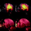
Fig. 1.
Schematic setup of the probehead when using a vertical bore main magnet.
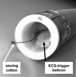
Fig. 2.
A 27-mm TEM resonator with pressure-sensitive balloon for respiratory gating and cardiac triggering.
Anesthesia induced by inhalation of isoflurane is the method of choice in our laboratories (see Note 3).
Required materials:
1.
Adjustable oxygen (O2) supply (cylinders with compressed oxygen).
2.
Isoflurane vaporizer.
3.
Narcosis container (cage-sized) with cap and hole for gas supply.
4.
PVC flexible tube (inner diameter ∼0.5 cm) for gas supply with three-way stopcock: O2 supply → isoflurane-vaporizer → O2 + isoflurane → switchable three-way stopcock. (a) First output: to the narcosis container/preparation desk (length ∼2–3 m). (b) Second output: to the MR coil (∼5–10 m, depending on the distance to the MR magnet).
5.
Nose cone to be applied on the PVC tube on the preparation desk (e.g., made from a 10-mL syringe (see Fig. 3)).
6.
A cone to cover the upper opening of the coil after positioning the mouse inside it (e.g., lower end of a 50-mL Falcon™ tube).
7.
A clock and a scale for protocol.
8.
ECG trigger unit (see below).

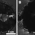
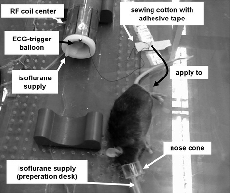
Fig. 3.
Overview of the animal preparation prior to the MR measurement.
Body temperature is kept constant using a temperature-controlled electrical warming pad designed for use in MR scanners (e.g., RAPID Biomedical GmbH). With experiments using coils of a very small inner diameter (20.0–30.0 mm), extra warming pads are not applicable. To stabilize the temperature of the sample volume inside the rf coil, the temperature adjustment of the gradient cooling unit can also be used. However, to find the right adjustments during different gradient duty cycles, preliminary experiments are required to measure the temperature while applying the desired pulse sequences.
Given a constant body temperature during the MR experiments, wildtype mice and ApoE–/– mice can be examined for a measurement time up to 2 h (8). However, when just examining plaque morphology at a limited vascular region, a total measurement time of 20–30 min is usually sufficient.
2.3 Cardiac Triggering and Respiratory Gating
When investigating vascular sections which are highly exposed to the cardiac and respiratory movements, dedicated trigger and gating mechanisms are necessary.
1.
Commonly, an electrocardiogram (ECG) signal is used to synchronize cardiac movement and MR data acquisition. Therefore, ECG electrodes are connected to the front limbs of the animal.
2.
The trigger signal is generated from the filtered electrical ECG signal with a dedicated trigger unit (RAPID Biomedical, Rimpar, Germany).
3.
Respiration is monitored using the pressure signal of a respiration sensor (Graseby Medical Limited, Hertfordshire, UK) transformed into an electrical signal outside the magnet with a pressure transducer (Honeywell Inc., Freeport, IL).
4.
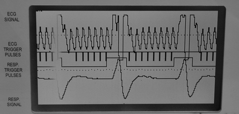
In case of strong interferences between the electromagnetic signal of rapid switching gradient pulses and the ECG signal, the respiration sensor can also be applied to monitor cardiac motion. When placed upon the cardiac region (see Fig. 2), the filtered and amplified signal shows both cardiac and respiratory motion (see Fig. 4).

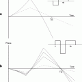
Fig. 4.
Signal obtained with the pressure-sensitive balloon for cardiac triggering and respiratory gating.
3 Methods
3.1 Animal Preparation
Mice should be kept in anesthesia shorter than 2 h. A good rule of thumb is that for every hour in anesthesia, an animal should be allowed to recover for 1 day without anesthesia. This is especially important in genetically engineered mice (e.g., ApoE–/–) or mice with invasively induced morbidities (e.g., ligature of the vasculature). These facts have impact on mortality during the experiment. If done routinely, the average time between induction of anesthesia and insertion of the probe into the magnet is 10–15 min. So:
Check the equipment before inducing anesthesia:
1.
Enough oxygen gas available?
2.
Isoflurane vaporizer filled? (One filling ∼3 mice).
3.
Supply lines connected correctly?
4.
Warming pad/lamp on preparation desk on?
5.
ECG trigger balloon connected correctly? Trigger unit setup adequate?
6.
MR scanner ready?
7.
Gradient cooling system temperature 33–38°C?
8.
Adhesive tape strips ready (two of ∼4 cm, one of ∼8 cm, one to fix the cap-cone onto the coil)?
Check the coil (all items are inserted from the bottom of the coil toward the probehead, see Figs. 1–3):
9.
Narcosis supply line inserted?
10.
ECG trigger balloon positioned within the coil center with leucoplast strips? This depends on the area you would like to investigate. The balloon must be positioned right over the apex of the mouse heart to ensure optimal trigger signal. The region of interest (ROI) should be right in the center of the coil. So if examining the thoracal aorta, position the heart and the balloon in the coil center.
11.
If necessary (for volume coils in which the animal should be pulled in), sewing cotton (loose end of ∼10 cm on the end of the probehead) thread through the probehead?
Then:
12.
Set three-way stopcock to the narcosis container line.
13.
Turn on O2 (flow 2 L/min) and isoflurane (4%) to flood container with gas.
14.
After ∼3 min, insert the mouse into the container. Record time as “narcosis induced” in measurement protocol.
15.
Wait for the mouse to fall asleep (∼2 min). Check gasping frequency (should be around 60/min).
16.
Weigh mouse while asleep and record weight.
17.
Connect the supply line from the narcosis container to the nose cone on the preparation desk (see Fig. 3).
18.
Set isoflurane flow to 2.5%.
19.
Apply mouse to nose cone. Make markings on the mouse (tail, ear, …) if necessary.
21.
Fix forefeet with second adhesive tape.
22.
Apply 8 cm leucoplast perpendicular to the one applied to the forefeet to allow “hanging” the mouse into the coil with it.
23.
Pull mouse into the coil by pulling the lower end of the sewing cotton. Mouse heart’s apex beat should be positioned over the ECG trigger balloon.
24.
Check trigger signal on the trigger unit.
25.
Fix mouse with leucoplast applied to the forefeet inside the coil. If coil is positioned vertically, the mouse should not move downwards.
26.
Set three-way stopcock to the gas supply line inserted into the coil.
27.
Close upper end of the coil (nose end of the mouse) with the cone to prevent anesthetic gas from leaking.
28.
Turn isoflurane flow to its definite value of 1.5–2%.
29.
Fix cap-cone with leucoplast.
30.
Check ECG trigger signal again.
3.2 MR Imaging
The steps in this section describe the imaging protocol using an MR system that comprises the following components: main magnet, Bruker Avance 750 (17.6 T); gradient system, 1000 mT/m (ID 40 mm, rise time 150 μs); rf coil, homebuilt transverse electromagnetic (TEM) resonator (ID 27 mm); trigger system, RAPID ECG Trigger Unit + respiration sensor (Graseby); and imaging software, ParaVision 4.0 (Bruker).
1.
Tune and match the rf coil according to the description in the Bruker manual (A-3-9).
2.
Generate a new scan (“New Scan” button) and select the scan protocol “A_TRIPILOT_GE_bas”. Adjust the following parameter with the spectrometer control tool (“Edit Method” button): field of view, 40 mm × 40 mm.
3.


Start adjustment routines with the “Traffic Light” button. The following standard adjustments are performed: linear-order auto shim to compensate field inhomogeneities, basic frequency adjustment, adjustments for the reference pulse gain (RF gain) and the receiver gain (RG).
Stay updated, free articles. Join our Telegram channel

Full access? Get Clinical Tree


