Primary Magnetic Resonance Imaging Magnets
Objectives
At the completion of this chapter, the student should be able to do the following:
• Identify the properties of various types of magnets used for magnetic resonance imaging (MRI).
• Describe superconductivity and its application to MRI.
• Discuss the terms cryogen, cryogenic gas, and cryostat.
• Convert temperature from one scale to another.
• Identify differences between high-field and low-field imaging.
Key Terms
The equipment necessary to perform magnetic resonance imaging (MRI) is complex and sophisticated. A systematic walk through the major components of the MRI system helps to clarify the system’s operation.
A schematic block diagram of a typical MRI system is shown in Figure 10-1. The major components of the gantry of an MRI system can be identified as either the primary magnets or the secondary magnets.
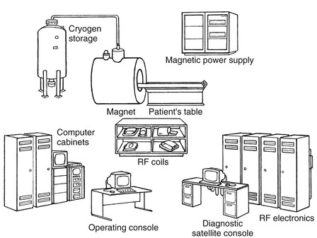
The primary MRI magnet produces the static magnetic field (B0). Secondary magnets are used to shim the B0 field and produce gradient magnetic fields (BX, BY, BZ). These fields are sometimes designated as GX, GY, and GZ. Finally, the radiofrequency (RF) system can also be considered as a secondary magnet. It includes transmit and receive coils. The shim/gradient coils and RF system are discussed in later chapters.
The primary magnet is the heart of the MRI system. The function of the primary magnet is to provide a sustained, homogeneous B0 during the MRI examination. The maintenance of a homogeneous B0 is required because B0 homogeneity affects image resolution, uniformity, and distortion.
At least two criteria in the selection of an MRI system are driven by the type of primary magnet: the desired field strength and siting limitations. Field strength and siting limitations are interrelated because for any given magnet design, increasing field strength increases the size of the associated fringe magnetic field. Fringe magnetic fields are the component of B0 that extend outside the magnet and its housing (see Chapter 30).
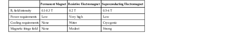
Basically, two types of magnets are used to generate B0: permanent magnets and electromagnets. Electromagnets can be further classified as resistive electromagnets and superconducting electromagnets (Box 10-1). Each magnet type has advantages and disadvantages with respect to these two important, often overriding, criteria: field strength and siting limitations. Although the following discussion considers each type of magnet, the main focus is on superconducting electromagnets, the type used in more than 95% of installed MRI systems. A brief comparison of these systems is given in Table 10-1.
Box 10-1
Types of Magnets Used to Generate B0
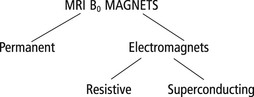
MRI, Magnetic resonance imaging.
Permanent Magnets
The permanent magnet is the most familiar type of magnet. This is the type of magnet used to demonstrate magnetic fields in science classes and to fix paper to refrigerators. Permanent magnets are components of compasses, motors, and audio speakers. They are inexpensive and widely used for simple applications.
 Permanent magnets occur naturally, or they can be synthesized.
The earliest commercial magnets were made of iron and called ferrite magnets. In the 1930s an alloy called alnico (aluminum, nickel, and cobalt) was developed with a slightly higher magnetic field than ferrite magnets. Alnico magnets have been made with ever-increasing magnetic field intensities. More recently, rare earth magnets have been introduced, which have even higher magnetic field intensity.
Although magnetic field strengths of up to approximately 1.2 T can theoretically be achieved with permanent magnets, field strengths of only about 0.3 T are practical for whole-body MRI systems due to their extreme weight. Figure 10-2 shows a typical permanent magnet MRI system.
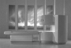
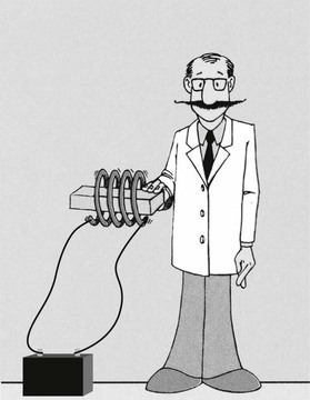
This design is often called an open MRI system because it enables parents to remain with their child during imaging. Open permanent magnet systems also make claustrophobic or anxious patients more comfortable. The magnetic field is typically produced by individual brick-size ferromagnetic ceramic materials that are rendered magnetic by charging them in the field of an electromagnet (Figure 10-3).
Once magnetized, these bricks are then carefully oriented into an array, up to 1 m on a side, containing two to five layers. The fabrication of such a large magnet made from smaller magnets is not a trivial task. The forces exerted are enormous, and if one brick is positioned incorrectly, contrary magnetic fields can result and cause the whole assembly to fragment violently.
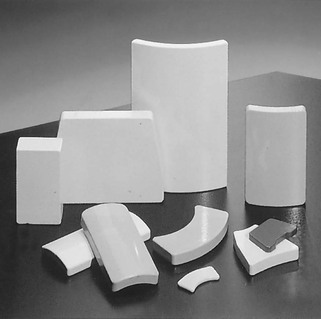
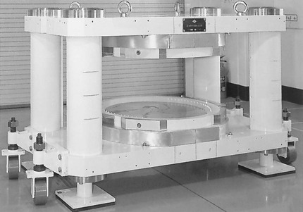
A variety of magnetic bricks are shown in Figure 10-4. Two assemblies are positioned opposite one another at a distance appropriate for head (50 cm) or whole-body (100 cm) imaging. A typical permanent magnet design is shown in Figure 10-5. In such a design the four corner posts are iron and provide a return path for the magnetic field.
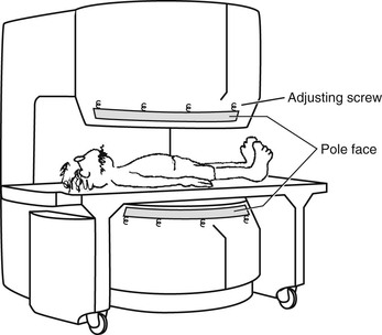
A pole face is positioned on each magnet assembly (Figure 10-6). These pole faces are carefully machined iron slabs designed to help orient and shape the B0 field and to increase its homogeneity within the imaging volume. Often there are adjusting screws or other mechanical shimming devices to further refine the homogeneity of the magnetic field after the imaging system is installed in a prepared site.
 Permanent magnets are shimmed with a pole face.
An iron yoke is in physical contact with each permanent magnet, and this contact serves three purposes. First, it provides a mechanical frame for assembly and stability. Second, it confines the fringe magnetic field by concentrating the lines of the magnetic field in this iron yoke. Finally, by containing the fringe magnetic field, the yoke also intensifies B0 in the imaging aperture. Without an iron yoke, B0 strength of such an assembly would be much less (Figure 10-7). The yoke is usually made of soft iron laminated and bolted together like a transformer core.
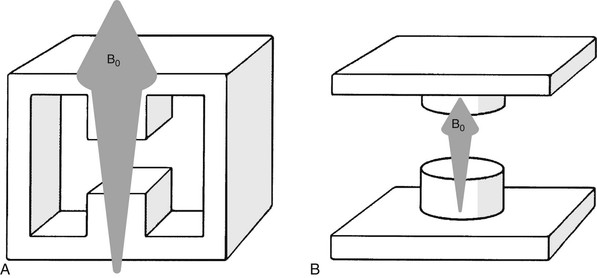
Table 10-2 presents the principal characteristics of a permanent magnet MRI system. The principal advantage of a permanent magnet MRI system is the insignificant fringe magnetic field, which for any MRI system must be no greater than 0.5 mT in any controlled area. This level is chosen out of consideration for patients with cardiac pacemakers; it is not hazardous to others.
TABLE 10-2
Characteristics of a Permanent Magnet Magnetic Resonance Imaging System
| Feature | Value |
| Magnetic field (B0) | Up to 0.3 T |
| Magnetic field homogeneity | 10-50 ppm |
| Weight | 90,000 kg |
| Cooling | None |
| Power consumption | 20 kW |
| Distance to 0.5 mT fringe field | <1 m |
The 0.5 mT field is within a few centimeters of the permanent magnet gantry because of the mass and design of the iron yoke. Other advantages of a permanent magnet MRI system include low electric power consumption and the absence of a cooling system.
The principal disadvantage of a permanent magnet MRI system is the limited B0 intensity. This places some restrictions on the type and complexity of imaging allowed. Other disadvantages include the relatively poor magnetic field homogeneity, usually about 20 parts per million (ppm), and the excessive weight. Poor magnetic field homogeneity results in reduced spatial and contrast resolution.
The weight of a permanent magnet MRI system limits its use to fixed sites. Although the fringe magnetic fields tend to be small, the weight of a well-designed permanent magnet MRI system can approach 90,000 kg (approximately 100 tons). This imposes significant mechanical considerations on the chosen location and usually excludes all but ground floor siting.
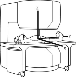
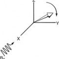
There is a fundamental difference between a permanent magnet MRI system and one of electromagnet design. The B0 field of a permanent magnet imaging system is vertical (Figure 10-8). Therefore the Z-axis is vertical rather than horizontal as in most superconducting electromagnet imaging systems. The long axis of the patient in a permanent magnet imaging system is the X-axis, and the lateral direction is the Y-axis. This corresponds to the axis identification in vector diagrams.
Permanent magnets are attractive for low magnetic field imaging applications because of their minimal fringe magnetic fields, low power requirement, and open architecture. However, the use of permanent magnets in clinical MRI is limited. This is because the maximum B0 intensity is low. Also the geometry of permanent magnets limits the efficiency of the gradient coils used with them. Because of this, MRI systems based on permanent magnets compromise the ability for some clinical applications, such as echo planar imaging. However, permanent magnet designs are being adopted for specialty MRI scanners, such as those dedicated to extremity imaging, because of their low cost and the small fields of view used in these applications.
Electromagnets
Related posts:


Stay updated, free articles. Join our Telegram channel

Full access? Get Clinical Tree


