Fig. 5.1
(a) Analogy of photography for spatial resolution: High-grain films (low spatial resolution) are more sensitive to incoming light (radiation exposure) but have lower detail resolution. (b) Small-grain films (high spatial resolution) are less sensitive to light (radiation exposure) but have higher detail resolution
Temporal Resolution
The temporal resolution depends on the gantry rotation time. For artifact-free imaging of the beating heart and the coronary arteries, a temporal resolution of less than 100 ms is desirable to permit reliable evaluation of these structures even at elevated heart rates [9].
In order to compensate for motion artifacts of the beating heart, the CT data acquisition is commonly synchronized with the ECG signal. The most commonly used approach for synchronization is retrospective ECG gating in which images are acquired throughout the cardiac cycle, and those time points depicting the coronary arteries without motion artifacts are retrospectively selected for image reconstruction. The projection data of a half gantry rotation is then required for image reconstruction (half-scan reconstruction), and thus, the temporal resolution corresponds to the half of the rotation time. Modern CT systems provide a gantry rotation time of down to 270 ms with a resulting temporal resolution of 135 ms. When using a mono-segment half-scan reconstruction method, further improvements in gantry rotation time are mandatory to achieve a temporal resolution of better than 100 ms. However, the mechanical forces increase with higher gantry rotation times. CT systems with a gantry rotation time of 330 ms are associated with a mechanical force of around 28 g. Therefore, rotation times of less than 200 ms required for a temporal resolution of 100 ms in a mono-segment half-scan reconstruction appear to be beyond today’s mechanical limits (i.e., mechanical forces > 75 g) [9].
The temporal resolution can be improved by using the scan data from more than one heart cycle for reconstruction of the images (multi-segment reconstruction) [10]. The images are then reconstructed using the partial scan data of projection sectors from multiple consecutive heart cycles resulting in a temporal resolution of up to a quarter of the rotation time when using two consecutive heartbeats and up to a sixth of the rotation time when using three heartbeats and so forth. Despite the theoretically improved temporal resolution, multi-segment reconstruction does not necessarily improve image quality as this algorithm is sensitive to changing heart rates. Therefore, the use of partial data from more than two consecutive heartbeats is usually not practical.
Another approach for improving temporal resolution at a given gantry rotation time is the dual-source CT system. A dual-source CT system consists of two X-ray tubes and two detectors mounted on the gantry with an angular offset of 90° working simultaneously. Therefore, only a quarter of rotation of each tube instead of a half of rotation with single-source CT is necessary to acquire the required projection data for image reconstruction. The temporal resolution improves to one quarter of the rotation time using only a single heartbeat for image reconstruction [8].
In photography, the shutter speed is analogous to the temporal resolution of CT. The shutter speed or exposure time is the effective length of time the camera’s shutter is open. Images taken at a low shutter speed, meaning a long exposure time [CT: low temporal resolution], will result in blurred display of moving structures (Fig. 5.2). Using a high shutter speed, meaning a short exposure time [CT: high temporal resolution], will result in a frozen display of the moving structure [CT: the heart].
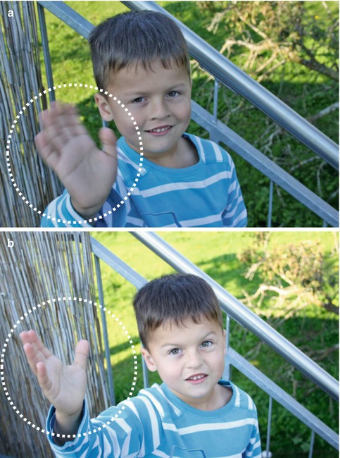
Fig. 5.2
(a) Analogy of photography for temporal resolution: Images taken at a low shutter speed (1/25 s), meaning a long exposure time (low temporal resolution), result in blurred moving structures. (b) Images taken at a high shutter speed (1/500 s), meaning a short exposure time (high temporal resolution), will result in a sharp moving structures
Z-Axis Coverage Speed
The coverage speed in z-axis is related to the longitudinal axis covered by the detector array, the gantry rotation speed, and the pitch value used. The higher the coverage speed in the z-axis, the shorter is the acquisition time. The scan time becomes important in CT imaging of patients being unable to hold their breath for a longer time or who are unable to cooperate (e.g., toddlers). One important benefit of short acquisition time is the lower occurrence of heart rate variability: A long breath-hold is frequently accompanied with tachycardia at the end of acquisition causing a considerable variability in the length of heart cycles [11]; a shorter breath-hold time reduces heart rate variability and may improve image quality of the images acquired during the end of the scan. In addition, when the scan time is reduced, there is also a shorter period required for the contrast opacification of the cardiac structures and consequently permits a smaller volume of contrast media to be used.
Recent Developments in CT Imaging
CT imaging has undergone a rapid technical improvement – in particular in the last 10 years. Modern CT systems provide high scan speed and high temporal and high spatial resolution. Thus, CT combines the advantages of widespread availability and short acquisition time. When being synchronized to the ECG signal, CT accurately delineates rapid moving cardiac structures and allows the assessment of the anatomical relationship of the coronary arteries to the adjacent structures and associated coronary artery anomalies [12].
Single-Slice Helical CT
The introduction of the single-slice helical CT into clinical practice was an important step toward the widespread utilization of CT in clinical routine improving the image quality in general and rendering CT fast enough for daily clinical routine. The gantry rotation time of single-slice helical CT was around 0.8 s which leads to a temporal resolution of 400 ms by using a half-scan reconstruction technique. The reconstructed slice thickness was about 3–5 mm. Although a better temporal resolution of 50–100 ms was available in the early 1980s with electron beam CT, single-slice helical CT established itself for cardiac imaging due to its availability in many institutions worldwide. In addition, newly introduced postprocessing techniques, including segmentation algorithms of the cardiac cycle, allowed to investigate a particular cardiac phase. When using a single-slice helical CT, occasionally the diagnosis of coronary artery stenosis in large proximal vessels [13], cardiac thrombus [14], and congenital heart disease [15] could be established under optimal conditions with very slow heart rates. However, most often the coronary arteries were displayed as “dancing vessels” or “ghosts” due to limitations in temporal resolution. Nevertheless, in consideration of the expected improvements of the temporal and spatial resolution, it became evident that cardiac CT imaging will become a practical and valuable tool despite the limitations present in these days.
Multi-Slice CT
The next step of CT evolution on the way to cardiac imaging was the implementation of multi-slice CT technology – coupled with a decreased size of the single detector element, the faster gantry rotation speed, and the increased volume coverage.
Since 1999 4-slice CT systems became clinically available providing gantry rotation times of 500–800 ms, resulting in a temporal resolution of 250–400 ms. The spatial resolution in z-axis was 1.0–1.25 mm and z-axis coverage was around 2 cm. The CT examination of the entire heart was feasible within a 40–50 s acquisition time – unfortunately being longer than most patients could hold their breath. Therefore, preoxygenation was often used to reduce breathing artifacts. Despite optimal preparation, only the proximal to mid coronary artery segments could be depicted without artifacts [16–24]. Images of distal segments and side branches suffered from the insufficient quality, and up to 32 % of coronary segments had to be excluded from analysis in the published 4-slice CT studies [22]. Therefore, the 4-slice CT system was still not robust enough to be implemented into daily clinical practice for cardiac CT imaging.
In 2001 16-slice CT systems became available. They provided gantry rotation times of 380–500 ms, resulting in a temporal resolution of 190–250 ms, and images were reconstructed with a slice thickness of 0.5–0.75 mm. The examination of the entire heart could be finished within a single breath-hold of around 20 s omitting the previous requirements of preoxygenation. In contrast to the 4-slice CT systems, even small coronary segments and side branches could be reliably evaluated [11, 25–34]. Nevertheless, 29 % of coronary artery segments remained not evaluative due to insufficient contrast attenuation in 52 %, to coronary artery motion artifacts in 45 %, to small vessel caliber in 31 %, to breathing artifacts in 19 %, and due to severe calcifications in 5 % [35]. Therefore, 16-slice CT systems were still not robust enough for cardiac imaging in all patients.
In 2004 64-slice CT systems became available. They provided gantry rotation times of 330–400 ms, resulting in a temporal resolution of 165–200 ms. The slice thickness was 0.5–0.625 mm, and detector covered 19.2–40 mm. The 64-slice CT systems allowed an examination of the entire heart within less than 10 s. Even detailed evaluation of small-sized branches of less than 1 mm in diameter was possible. The improvements in temporal resolution and the z-axis coverage speed allowed a precise characterization of the morphology and function of the aortic [36–40] and the mitral valve [40, 41]. Therefore, the 64-slice CT has been considered the first CT system being robust enough for cardiac CT imaging in daily clinical practice [42–50]. Despite its improved temporal resolution, the 64-slice CT system still needed a low and stable heart rate for optimal image quality [51], making a premedication with beta-blockers prior to coronary CT angiography frequently required. However, a precise morphological and functional evaluation of the heart of CHD patients could be commonly performed without medicamentous heart rate control.
State-of-the-Art CT Systems
The remaining challenges of temporal resolution and detector coverage have led to the development of the latest CT systems: 256-/320-slice CT and dual-source CT.
Large Volume Coverage CT (256-Slice CT/320-Slice CT)
In order to overcome limitations of CT for coronary visualization in patients with irregular heart rhythm, Toshiba introduced in 2006 the first CT system capable of covering the entire heart within a single heartbeat, using a large detector system with a 256-slice detector array and a spatial resolution of 0.5 mm resulting in a z-axis coverage of 128 mm. These technical improvements permit coverage of the entire heart in a single gantry rotation. On the other hand, because of increasing weight of the rotating elements, this CT system is limited by its long gantry rotation time of 500 ms. Nevertheless, initial results from small patient cohorts show great promise for assessing coronary artery stenosis with the 256-slice CT system [52, 53]. In 2007 Philips introduced another 256-slice CT system but with a lower gantry rotation time of 270 ms. Later, a 320-slice CT system with a detector coverage of 160 mm and a gantry rotation time of 350 ms was introduced by Toshiba. First results show great promise for imaging the coronary arteries within a single heartbeat [54]. Large volume coverage CT might open the field for new cardiac imaging applications, including observation of evolving processes such as coronary contrast flow and whole heart perfusion.
Dual-Source CT
In 2005 Siemens introduced a CT scanner with two X-ray tubes and two corresponding detectors mounted onto the rotating gantry with an angular offset of 90°, the so-called dual-source CT [8] (Fig. 5.3). Each detector array of the first generation of dual-source CT is capable of acquiring 64 slices. This construction led to a reduction of the rotation needed to acquire the required projection data for image reconstruction from half a rotation in single-source CT to a quarter of a rotation in dual-source CT. Thus, the gantry rotation time of 330 ms results in a temporal resolution of 83 ms in a mono-segment reconstruction mode that is consistent throughout various heart rates owing to individual adaptation of the table pitch. Due to the high temporal resolution, several studies demonstrated a high diagnostic accuracy of dual-source CT for the assessment of coronary artery stenosis combined with a low rate of nonevaluative coronary segments [55–62] and permits coronary imaging even at high heart rates [8, 63, 64]. In addition, by operating both tubes at different tube voltages, dual-energy cardiac CT can be performed, which may help to identify myocardial perfusion defects [65].
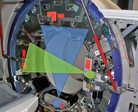
Fig. 5.3
Dual-source CT: Two corresponding detectors are mounted onto the rotating gantry with an angular offset of 90°
Recently, Siemens introduced the second-generation dual-source CT which is capable of acquiring 2 × 128 slices. The gantry rotation time has been reduced to 280 ms, leading to a temporal resolution of 75 ms. In contrast to the other CT systems, where a low pitch is needed for overlapping data acquisition, the second-generation dual-source CT can achieve gapless z-axis sampling even at a pitch value of up to 3.2. Therefore, it enables coverage of the entire heart in a single heartbeat.
Development of Technical Parameters
The development of multi-slice CT scanners led to an enormous improvement of the technical parameters defining the cardiac imaging capabilities.
Development of Spatial Resolution
Compared to 64-slice CT systems, the temporal resolution has not substantially improved with 256-slice/320-slice or dual-source CT systems. Interestingly, blooming artifacts of severely calcified vessels walls are less pronounced in dual-source CTCA than in 64-slice CTCA [55]. Given that the spatial resolution of single-source 64-slice CT and dual-source CT is the same, this difference in calcification dependency could indicate that blooming artifacts may be sometimes superimposed by additional motion artifacts [55] and thus be dependent on the temporal resolution. Therefore, artifacts from clip material and devices might be reduced in CT imaging of CHD patients after surgery when using state-of-the-art CT systems.
Development of Temporal Resolution
A gantry rotation time of less than 100 ms is required to overcome the challenge of motion artifacts at high heart rates. In order to achieve this goal, two different approaches have been developed: the multi-segment reconstruction algorithm and the dual-source concept.
In the multi-segment reconstruction concept, small portions of projection data are selected from two or more heart cycles, and all projections are combined to obtain sufficient data for image reconstruction. The maximal achievable temporal resolution is half of the gantry rotation time and divided by the number of heart cycles averaged for image reconstruction. Although effectively improving the temporal resolution, the multi-segment reconstruction approach may be a cause of additional motion artifacts. The cardiac position in the thoracic cage is not absolutely fixed and depends on the actual ventricular filling and function, even at a steady heart rate. Due to merging of data from two or more consecutive cycles, the resulting image data do not exactly match together, leading to motion artifacts. These motion artifacts are even seen in patients with regular heart rate and more pronounced in patients with variable heart rate and result in an increased vessel blurring [51, 66, 67]. These disadvantages have even been reported for modern CT systems with high temporal resolution [68].
The other approach to improve the temporal resolution is the dual-source CT concept. Because images are obtained in a quarter of the rotation, the temporal resolution is around 75–83 ms using a mono-segment reconstruction from a single heartbeat for the individual image thereby avoiding artifacts from averaging projection data from several consecutive heartbeats. Several studies have shown improved image quality by reducing motion artifacts without administration of beta-blockers for heart rate control [55–57, 61].
Development of Z-Axis Coverage
The z-axis coverage speed has tremendously increased during the CT development. While acquisition of the entire heart needs more than 40 s with a 4-slice CT and around 20 s with a 16-slice CT, the acquisition with current 64-slice CT systems takes less than 10 s. With the most advanced CT systems (e.g., 320-slice CT and second-generation dual-source CT systems), the entire heart is imaged within a single heartbeat.
The increase in z-axis coverage speed led to a concomitant decrease in the amount of contrast media required for cardiac CT. The contrast media amount was reduced from 160 mL in the beginning of cardiac CT with 4-slice CT systems [69] to around 50–80 mL with 320-slice CT and dual-source CT [54, 55, 57, 61, 64, 70]. Therefore, state-of-the-art CT systems have the potential to reduce the risk of contrast-induced nephropathy.
CT Imaging Protocols in CHD Patients
All protocols and recommendations within this section are valid for current dual-source CT systems but might be easily adapted to other CT systems. The CT imaging protocol should be adapted according to the suspected cardiac defect, the type of previous surgical repair, and the patient’s compliance. The relevant CT parameters for CHD imaging in adult patients are summarized in Table 5.1.
Table 5.1
Relevant CT parameters for imaging adult patients with congenital heart disease using a dual-source CT system
Slice collimation | Thin collimation: 2 × 64 × 0.6 mm |
Thick collimation: 2 × 24× 1.2 mm | |
Tube voltage/tube current | BMI ≤25 kg/sqm: 100 kVp/150 mAs (ECG-synchronized: 100 kVp/220 mAs) |
BMI >25 kg/sqm: 120 kVp/180 mAs (ECG-synchronized: 120 kVp/330 mAs) | |
Gantry rotation time | 330 ms |
Pitch | 1 (non-ECG-synchronized CT) |
0.2–0.5 (retrospective ECG-gated CT; pitch depending on the heart rate) |
Patient Preparation
Good image quality is one of the key factors for a good diagnosis and additionally reduces the time needed for interpretation of the cardiac CT study. Therefore, every patient preparation should be optimized for the scan to be successful. Many of the steps that ensure a good image quality take place even before the scanning begins.
Patient preparation includes instruction to the patient, correct positioning of the patient on the CT table, ECG lead placement if ECG synchronization is intended, and placement of a peripheral venous catheter for the contrast agent. The size of the venous access line depends on the CT protocol. For high-quality CT angiographic images, an 18-gauge or larger catheter is the preferred administration route. A right-arm injection is preferable to avoid artifacts from undiluted contrast agent in the left brachiocephalic vein.
Although the rate of not-evaluative coronary segments has been markedly declined when using modern scanner types, a low and particularly regular heart rate is still one of the major determinants for good image quality. Thus the patient should be imaged in a calm and comfortable ambience to avoid influences on the heart rate by anxiety or agitation. We give patients explicit breathing instructions and practice correct breathing without pressuring before the scan. The patient is instructed to suspend respiration at the appropriate time and to hold still during the scan. The patient is also informed about the possible instantaneous effects of contrast material including warmth, pelvic tingling, and a metallic taste in the mouth to minimize worry during the examination.
When to Use ECG Synchronization and When Not?
Data acquisition in cardiac CT can be performed non-ECG-synchronized or synchronized to the ECG signal by retrospectively gated or prospectively triggered techniques. In general, ECG synchronization leads to a reduction of motion artifacts but increases the radiation exposure [71]. For most instances, the non-ECG-synchronized technique is sufficient, while ECG synchronization is mandatory in patients with a complex cardiac abnormality or a small-sized intracardiac abnormality or communication or when the coronary arteries need to be investigated.
Non-ECG-Synchronized CT
Non-ECG-synchronized cardiac CT provides a fast acquisition of the cardiac and extracardiac structures, but due to heart motion artifacts, it is less suited for the detailed visualization of small cardiac and coronary structures. Using a pitch of around 1 is usually a good balance between acquisition time, radiation dose, and image quality. To reduce radiation dose and improve image quality in non-ECG-synchronized CT, thicker detector collimation is preferred, at the expense of reduced visualization of small-sized structures. Furthermore, when using a thicker collimation, the acquisition time is lower, and thereby, the respiratory motion artifacts might be reduced. If possible, non-ECG-synchronized CT in patients with CDH is performed during breath-hold. If this is not possible, the CT examination could be performed in free-breathing technique, avoiding excessive respiratory excursion. In modern CT systems, respiratory artifacts are less pronounced. It has been reported in non-ECG-synchronized CT acquisitions that 82 % of patients with CHD, the origins and proximal segments of the coronary arteries are evaluative [72]. The radiation dose of this scan technique in young children is usually less than 1 mSv [73].
ECG-Synchronized CT
The synchronization of the CT data acquisition with the ECG signal is important for sufficient compensation of cardiac motion artifacts and is of utmost importance for the evaluation of small-sized cardiac structures, intracardiac communications, and the coronary arteries and commonly improves visualization of the aortic root. The ECG synchronization can be performed with three different acquisition modes: retrospectively ECG-gated helical CT (single- and dual-source CT), prospectively ECG-triggered sequential CT (single– and dual–source CT), and prospectively ECG-triggered high-pitch helical CT (only dual-source CT).
Retrospective ECG Gating
For a long time, retrospective ECG gating has been the standard acquisition mode for helical cardiac CT. In retrospective ECG-gated CT, the data acquisition is performed with continuous scanner table motion and spiral acquisition with overlap of the radiation beam on each spiral synchronized to the ECG (Fig. 5.4a). Thus, low pitch values are necessary for gapless data acquisition, and radiation dose are substantial higher than when using non-ECG-synchronized CT as each portion of the heart is imaged more than once, while ECG is recorded. Then, in the retrospective, images are reconstructed in the optimal phase of the cardiac cycle providing the least motion artifacts and used for the interpretation. The surplus of information across different phases of the cardiac cycle can be used for ventricular functional analysis.
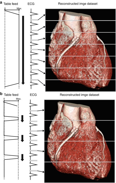
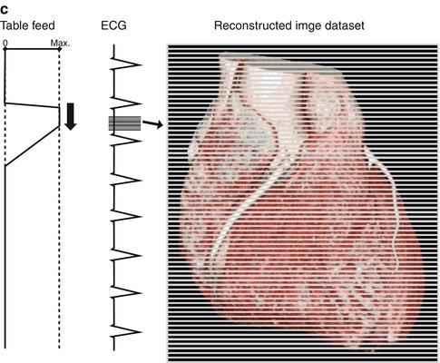
Fig. 5.4
(a) Retrospective ECG gating: The data acquisition is performed with continuous scanner table motion and spiral acquisition with overlap of the radiation beam on each spiral synchronized to the ECG. Then, in the retrospective, images are reconstructed in the optimal phase of the cardiac cycle providing the least motion artifacts. (b) Prospective ECG-triggered CT: The patient is irradiated only at selectable heart phases, and the table is moved in a sequential manner, remaining stationary while data are acquired. (c) High-pitch helical prospectively gated CT: This scanning mode permits cardiac CT to be performed in a small fraction of a single heartbeat. Because the high-pitch scan is limited to the diastole in a single heartbeat, the heart rhythm needs to be prospectively predicted
Prospective ECG Triggering
If there is a high probability that just a single reconstruction in the diastole is required for a diagnostic image, usually in patients with a low and stable heart rate, prospectively ECG-triggered sequential CT is an alternative acquisition mode. Using this mode, the CT table is stationary during image acquisition and moves in the following heartbeat to the next position for the next sequential scan (“step-and-shoot mode”) (Fig. 5.4b). With a 64-slice CT, complete coverage of the heart requires 5–8 heartbeats, with a 128-slice dual-source CT 2–3 heartbeats and with a 320-slice CT only a single heartbeat. The radiation dose of prospectively ECG-triggered sequential CTCA is low with an effective radiation dose of 1–4 mSv because there is little overlap between adjacent sequential scans and X-ray exposure is limited to a small interval in the cardiac cycle [74, 75]. Prospective ECG triggering can be used to reduce radiation dose in other types of cardiac CT studies as well, such as evaluation of coronary artery bypass grafts [76] and triple-rule-out studies in acute chest pain [77]. Several studies have demonstrated a high diagnostic accuracy of prospectively ECG-triggered coronary CT angiography [74, 78, 79]. A heart rate threshold of up to 70 or 65 bpm is used in most of the studies performing ECG-triggered CTCA. Husmann et al. [80] reported that 98.9 % of all coronary artery segments were evaluative at heart rates of up to 63 bpm, while only 85 % were assessable at higher heart rates. Faster CT systems and advanced acquisition techniques may increase the heart rate threshold in prospectively gated CT above the level of 70 bpm, at a similar ability to assess coronary segments as in retrospective ECG gating [81].
In prospective ECG–triggered CT, the patient is irradiated only at selectable heart phases, and the table is moved in a sequential manner, remaining stationary while data are acquired. This leads to smaller effective patient dose of 1–3 mSv in adults [82] and 0.2–0.7 mSv in newborns and infants [83]. Limitations of this technique are the missing ability to assess the ventricular function and the impairment of the image quality in case of arrhythmia. Nevertheless, prospective ECG-triggered CT has almost completely replaced the retrospective ECG-gated acquisition in patients with CHD. For patients with heart rates <75 bpm, we predefine the data acquisition in the diastolic phase at 70 % relative to the R-R interval and for patients with a heart rate of more than 75 bpm in the systolic phase at 30 %. We still perform a retrospective ECG-gated CT – if ECG synchronization is required – in patients with arrhythmia and if multiphase functional evaluation is required.
Most recently, an adaptation of the prospective ECG-triggered CT technique to a dual-step mode has been introduced to provide ventricular functional analysis at low radiation dose [84].
High-Pitch Helical Prospectively Gated CT
In order to gain sufficient projection data from image reconstruction in retrospectively ECG-gated cardiac CT, pitch is usually limited to low values of 0.2–0.5. Higher pitch values would result in less projection overlap. If the pitch is increased to more than 1.5, projection gaps will occur resulting in severe artifacts. In dual-source CT systems, the second tube-detector combination can fill these projection gaps occurring at high pitch values. Pitch values of 3.2–3.4 are feasible using a second-generation 128-slice dual-source CT system, leading to an acquisition time of approximately 250 ms (Fig. 5.4c). This permits cardiac CT to be performed in a small fraction of a single heartbeat. Because the high-pitch scan is limited to the diastole in a single heartbeat, the heart rhythm needs to be prospectively predicted. Therefore, it is essential for high-pitch helical prospectively gated CT to only be performed in patients with low and regular heart rates. Radiation dose is very low due to the short acquisition time and the little overlap between spiral acquisitions. Achenbach et al. [85] evaluated high-pitch helical prospectively gated CT in 50 patients with a body weight of less than 100 kg and a heart rate of 60 bpm or less with a resulting radiation dose of 0.9 mSv. Leschka et al. [86] reported a high diagnostic accuracy of high-pitch coronary CT angiography for the assessment of coronary artery stenosis at a submillisievert radiation dose. Alkadhi and colleagues [78] investigated the diagnostic performance of high-pitch cardiac CT in comparison to prospectively ECG-triggered CT in patients with a heart rate of less than 70 bpm and found similar diagnostic accuracies for the assessment of coronary artery stenosis at a 30 % lower radiation dose at high-pitch CT. In addition, high-pitch helical prospectively gated CT can be used to evaluate the coronary artery bypass graft patency at a low effective radiation dose of approximately 2.3 mSv [87].
Selection of Protocols Depending on the Type of CHD
The scan range and the acquisition mode and whether ECG synchronization is performed depend on the type of CHD to be investigated. Table 5.2 provides recommendations for CT protocols for different CHDs.
Table 5.2
Recommended scan range and ECG synchronization depending on the congenital heart disease type
Congenital heart disease type | Scan range | ECG synchronizationrequired? | Comment |
|---|---|---|---|
Aortic coarctation | Aortic archto diaphragm | No | Thin collimation is recommended for identification of collateral pathways |
Anomalous pulmonaryvenous return | Aortic archto diaphragm | No | Scan range should be extendedto the level of the kidneys in the infracardiac type |
Patent ductus arteriosus | Aortic archto diaphragm | No | Thin collimation is recommended for identification of small ductus arteriosus |
Persistent superior leftvena cava | Aortic archto diaphragm | No | |
Atrial septal defect | Below tracheal bifurcation to diaphragm | Yes | ECG synchronization may be beneficial for small intracardiac shunts |
Ventricular septal defect | Below tracheal bifurcation to diaphragm | Yes | ECG synchronization may be beneficial for small intracardiac shunts |
Tetralogy of Fallot | Above the pulmonary bifurcation to diaphragm | No | – |
Common aortic-pulmonarytrunk | Above the pulmonary bifurcation to diaphragm | No | – |
Transposition of the great arteries | Above the pulmonary bifurcation to diaphragm | No | – |
Univentricular heart | Below tracheal bifurcation to diaphragm | No | No saline chasing bolus should be used to avoid washout |
Double outlet ventricle | Above the pulmonary bifurcation to diaphragm | No | No saline chasing bolus should be used to avoid washout |
Isomerism | Below tracheal bifurcation to diaphragm | Yes | ECG synchronization is recommendable for morphological identification of the atrial appendages to determine sideness; the scan range must include the thorax and spleen for identification of extracardiac abnormalities |
Coronary artery anomaly | Below tracheal bifurcation to diaphragm | Yes | Thin collimation and ECG synchronization are mandatory |
Contrast Agent Application
To avoid high-contrast artifacts in the left brachiocephalic vein, a right-arm contrast media injection is preferable. In neonates and young children, nonionic iodinated contrast agent is injected at a dose of 2 mL per kg body weight to a maximum amount of 100 mL. The injection rate is set at 1 mL/s but might be increased to 2 mL/s in patients with a large intracardiac communication. In adults, 1.5 mL/kg body weight is injected at a rate of 3–4 mL/s. A saline bolus should be applied after the injection of the contrast media to reduce the artifacts from undiluted contrast media and to reduce the total amount of contrast media. To determine the scan delay in ECG-synchronized CT, the bolus-tracking technique is advantageous. For this purpose, the region of interest (ROI) in pediatric patients is placed in the left ventricle, and a threshold attenuation of 200 HU is set. However, when in doubt about the intracardiac connections and the timing of the contrast attenuation of the different cardiac chambers, in the individual patient monitoring the arrival of contrast material in the cardiac chambers and manually starting the CT acquisition is often the safer way for sufficient contrast attenuation of the cardiac cavities and adjacent arteries and veins. In adult patients, the ROI is placed in the ascending or descending aorta, and the attenuation threshold is set at 140–180 HU.
When performing a non-ECG-synchronized CT in pediatric patients, a fixed scan delay is usually sufficient. The start delay is set on 12 s for peripheral injection and on 8 s for central venous injection.
Image Reconstruction and Postprocessing
On the axial images, the oblique orientation of the heart often leads to unfavorable cutting angles and partial volume effects. The image reconstruction technique used depends on the diagnostic task, and usually a combination of different visualization techniques is required. In addition, to facilitate the communication between the radiologist and the referring physician, the presentation of the findings should be adapted to the field of the referring physician. For example, while surgeons will prefer realistic 3D images simulating a surgical view, cardiologists are used to conventional angiographic images. To generate the desired presentation, axial data need to be processed.
Multiplanar Reformation (MPR)
MPR is a 2D postprocessing technique allowing to display one plane inside the original 3D image volume (Fig. 5.5). This plane may be orthogonal to the axial slices of the image volume (i.e., coronal or sagittal MPR), oblique, or replaced by an arbitrary curved surface (i.e., curved MPR). In cardiac CT oblique, MPR is often used to show the four-chamber view and the short-axis view. To display the complete course of a vessel in a single 2D image, curved MPR enables to align a course along the vessel centerline. Current dedicated workstations permit an automatic definition of the vessel centerline after the user has selected one or more seeding point inside the lumen of the vessel. A drawback of the curved MPR technique is that only a single vessel branch may be displayed at any time. MPR is the most popular method of reconstruction in cardiac CT. Due to its easy handling, MPR is least susceptible to wrong operation by the radiologist among all postprocessing techniques. Nevertheless, continuous adaptation of the reformatted planes is required to avoid improper plane orientation which might introduce false or mask pathological findings.
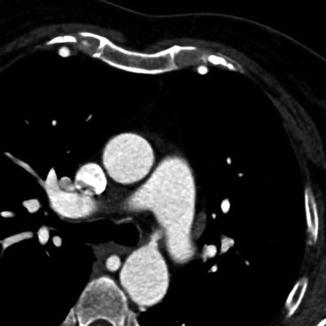
Fig. 5.5
Multiplanar reformation (MPR) technique in a patient with an aortic coarctation displaying one plane inside the original 3D image volume
Maximum Intensity Projection (MIP)
MIP is the simplest 3D postprocessing technique. A virtual camera sends multiple beams through the 3D volume dataset, whereas only the highest-attenuation voxels are retained, allowing a fast display of a part of the total dataset. The parameters that have to be chosen are the window setting and the beam angulation which determine the viewing orientation. MIP is suited to display vascular structures in a single image (Fig. 5.6a). Sometimes, the significant information reduction in MIP proves to be a disadvantage. When applied to the entire image volume, the vascular structures can be overlaid and therefore be obscured with the cardiac cavities filled with contrast agent, high-attenuation pericardial metallic clips, or bones of the chest (Fig. 5.6b). Thin-slab MIP is a technique to remove high-attenuation voxels of surrounding structures from the rendering by cutting planes in front and behind a vessel. In defiance of these shortcomings, MIP has become an important complementary tool for the visualization of thoracic vasculature.
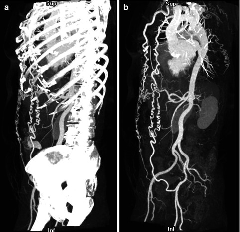
Fig. 5.6
(a) Maximum intensity projection (MIP) technique applied to the entire image volume in a patient with aortic coarctation. The bones obscure the vascular structures. (b) Thin-slab MIP in the same patient: The high-attenuation voxels of the bones are removed, leading to an improved visualization of the vascular structures and the collateral circulation in aortic coarctation
Direct Volume Rendering (DVR)
As in the MIP technique, a virtual camera sends multiple beams through the 3D volume dataset, but, in contrast to the MIP technique, a physically based model defines the attenuation properties of each voxel density encountered along the beam. A transfer function maps Hounsfield units to colors and opacities that are then integrated along the beam. Therefore, a color defines a distinct structure, and separate tissues can be classified and rendered from completely transparent to completely opaque. To enhance the 3D impression, the image volume usually is illuminated with a virtual external light. Direct volume rendering technique is able to produce realistic images and provides a good overview of the anatomy (Fig. 5.7a, b). In general, the multitude of parameters renders DVR a computationally intensive and time-consuming postprocessing technique. Albeit DVR being an excellent “nature-like” display of the cardiac and extracardiac structures for the referring physician, DVR is very susceptible to wrong operation by the radiologist and inappropriate setting may mask or artificially display a pathological finding.
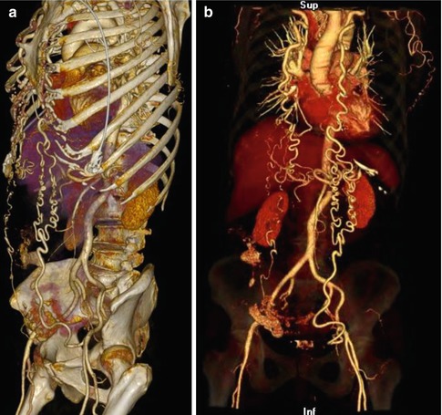
Fig. 5.7
(a) Direct volume rendering (DVR) technique in a patient with aortic coarctation clearly providing the anatomical details. (b) Direct volume rendering (DVR) technique in a patient with aortic coarctation: The opacity of the bone dense Hounsfield units is reduced displaying them transparent, leading to an excellent visualization of the vascular structures
Radiation Dose Issues
In any CT study, the ALARA principles (“as low as reasonable achievable”), i.e., dose reduction to the lowest value maintaining image quality at a diagnostic level, should be followed. The balance between low radiation dose and diagnostic image quality is the most crucial step in radiation dose reduction. If the CT study loses its diagnostic capability to answer the clinical question of interest due to excessive dose reduction, there is no benefit for the patient [88]. However, the application of more radiation dose than needed to answer the clinical question will unlikely increase the diagnostic capability of the study and may harm the patient [88]. The goal is to acquire at least diagnostic image quality and not best achievable image quality. To achieve this goal, familiarity with more noisy images is a must.
PROTECTION I, a large international multicenter trial, has identified several predictors of higher radiation exposure in cardiac CT [89


Related posts:
Stay updated, free articles. Join our Telegram channel
Full access? Get Clinical Tree
