Radiation treatment planning: immobilization, localization and verification techniques

Chapter 9 Radiation treatment planning


immobilization, localization and verification techniques


Introduction


The treatment planning process consists of a series of patient-related work tasks that eventually result in a custom plan of the external beam treatment and will enable the radiation dose prescription to be applied. The Radiation Treatment Planning (RTP) system provides a 3D dose distribution of the beams arranged around the body using a mathematical model of the megavoltage x-ray field. The composite dose map is displayed in relation to the target volume and the critical anatomical structures within the body.


Integral to the planning process are devices that ensure the treatment is reproducible on a daily basis; the most important of these is a method of reducing movement of the patient during treatment, and this is called ‘immobilization’. The specification of such a device is dependent on the area of the body for which it is required. For treatments of the head and neck, some form of immobilization device is essential to ensure reproducible set-up and to avoid displacement of the plan isocentre from its intended position. The relatively small field sizes used in the head and neck, compared with pelvic or thorax plans, requires a high degree of beam positional accuracy, because of the proximity to critical organs (e.g. eye, spinal cord), which depends on effective immobilization of the head. Other devices that facilitate reducing movement of the patient are site specific. For example, external beam radiation treatment of the breast utilizes a board that supports the patient at an inclined angle and provides hand grips that raises their arms above their head to meet the requirements for glancing beams arranged to the breast. Other devices stop the patient from moving their legs to reduce lower body movement or can make the treatment more sustainable over the few minutes of the beam exposure time.


Complete eradication of patient movement is impossible to achieve, although reducing this to within acceptable tolerance (e.g. 3   mm for head and neck, 5   mm for thorax and pelvis) is commonly achieved. Another technique to improve beam positional accuracy is to track the movement of the patient or movement of anatomical landmarks using an external device that is integral with the treatment accelerator – this method is called ‘Image Guided Radiotherapy (IGRT)’. IGRT requires monitoring of the patient using a real-time imaging device (e.g. video, ultrasound, x-ray) and the information is compared with the patient plan to correct for any positional inaccuracy. This technique enables a precise level of beam positioning control that can allow for any inadequacies in immobilization or effects of organ movement (e.g. lung displacement during respiration).


Anatomical information of the patient in the treatment position is required in order to undertake 3D treatment planning. The process of ‘localization’ includes the acquisition of either radiological images from a simulator and/or tomographic scanner (e.g. x-ray computer tomography, CT). The localization process provides external contour information and anatomical data that enable definition of planning target volume (PTV) contours and organs at risk (OAR); methods of providing this information range from x-ray CT, magnetic resonance imaging (MRI) through to positron emission tomography (PET). However, the basic requirement, to define the external contour and internal structures for treatment planning, are provided by a CT data set of the patient that can be transferred to the ‘Treatment Planning System’ (TPS) where attenuation data are converted to ‘electron density’ values for heterogeneity correction of the megavoltage beam data. Non-x-ray CT imaging modalities cannot provide this attenuation correction.


The production of an optimized treatment plan for external beam megavoltage treatment is highly dependent on the following:


A customized treatment plan for the patient must be checked prior to first treatment to ensure the accuracy and validity of the plan, this process is called ‘verification’.


Verification of the plan can be undertaken on a simulator where radiographic images of each beam portal can ensure the accuracy of the isocentre position and verify the beam size and shape against the treatment plan. Alternatively, a process called ‘Virtual Simulation’ allows the use of the original CT information to produce a ‘Digitally Reconstructed Radiograph’ (DRR) of the beam portal that provides a ‘virtual film’ that is comparable to the simulator image.


Patient immobilization


Patient head shells


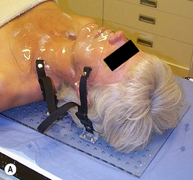
The majority of patients receiving radiotherapy to the head and neck region are immobilized using a custom made shell that accurately fits to provide effective and reproducible positioning of the head at all stages of planning and treatment. Typically, the process used to fabricate a clear plastic shell, Figure 9.1A requires a plaster cast of the patient’s head to be first produced. The transparency of the plastic enables the accuracy of fit to be checked with minor adjustments being made to ensure the shell must be a good fit, achieving the optimal position for treatment, while maintaining patient comfort.


Typically, the following steps are required to produce a full head shell:


1. the patient should assume the position to be adopted in the treatment room; this usually involves a headrest that supports the neck and inclines the head at the required angle for treatment. Separate impressions are taken of the front and back halves of the head


2. an impression of the back half of the patient’s head is made using, for example, plaster of Paris bandage or dental alginate, which covers an area up to a coronal plane at the level of the ears


3. before taking a similar impression of the front half of the head a few precautions are necessary to ensure patient comfort. The patient should breathe normally through the nose and ‘separating cream’ should be used on the skin to enable easy removal of the plaster cast. In some circumstances, a tissue-equivalent mouth insert will be required to depress and fix the tongue


4. the plaster bandage should be shaped carefully round the bony protuberances of the head in order to facilitate good fitting of the shell and to provide effective immobilization. The two plaster impressions front and back must fit uniquely together once they are removed from the patient. Further layers of plaster bandage are applied to the two halves to provide rigidity and, once hardened, are removed from the patient


5. the two halves are fixed together with further plaster bandage over the joints and the impression is filled with a thin mix of plaster and allowed to set overnight


6. the final solid cast is trimmed and sawn in half along a suitable coronal plane. The cast is now ready for vacuum forming


7. the flat surface of each half cast is placed on the vacuum forming machine. A large plastic sheet is heated and stretched into a bubble before the casts are raised and the vacuum applied to form a tight skin around the surface of the molds


8. the excess plastic is trimmed from each shell to provide a flange that enables the two halves to be held together with plastic press-studs. Side supports are molded and attached to the shell to enable it to be fixed to the treatment head support.


Thermoplastic shells


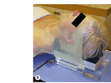
Commercial systems are now widely available that do not require vacuum forming techniques; these perforated thermoplastic materials may be softened in a hot-water bath or warm oven and shaped directly onto the patient, Figure 9.1B. This system utilizes a U-frame in which the attached thermoplastic, when heated and softened, stretches from the tip of the nose to the baseplate, where the U-frame is indexed and locked down. While this system is very easy to use and provides a snug fit for excellent fixation, it also can, in some cases, exhibit shrinkage, leading to patient discomfort due to the stretching of the thermoplastic required with this type of system. Stretching resulting from prolonged use during the course of treatment can lead to inaccuracies in set-up and, although here is a cost benefit from repeated use, sterilization requirements can limit this.


A reinforced thermoplastic is also available that improves rigidity, comfort, and immobilization. Solid thermoplastic reinforcement strips, melted into the perforated sheet, provide rigid fixation and rotational stability necessary for treatments requiring more precise immobilization such as intensity modulated radiotherapy (IMRT) and conformal radiotherapy treatments.


These thermoplastic shells are a particularly attractive alternative to the vacuum formed shells to those sites which do not have extensive pretreatment preparation facilities. The material is easily molded, transparent and the perforations allow visual assessment of the final fit.


Non-shell fixation systems


These systems of head restraint are based on a custom impression of the patient’s maxillary teeth and hard palate fixed to a plastic dental bite block (tray). Some designs incorporate a vacuum applied through the bite block that secures it to the maxillary structures; a vacuum pump is placed on the treatment couch and attaches to the mouth tray via a suction tube. Any decrease in pressure indicated by the vacuum gauge is indicative of a misplacement of the bite block. The mouthpiece is attached to two hollow carbon-fiber composite columns mounted on a baseplate by a patient-specific fixation set consisting of a transverse plate and an angle plate. Moving the plates against each other gives enough degrees of freedom to provide exact positioning. Once adjusted, the fixation set stays assembled throughout the entire treatment ensuring precise repositioning for the next fraction. A laser localizer box, consisting of side Perspex plates and top plate, are attached to the baseplate for daily set-up. Etched lines on the plate aid in visualizing the laser lines projected on the plates. This localizer box is removed prior to treatment.


This type of non-shell fixation can be as accurate as head shell methods provided that no displacement of the mouth bite occurs that could compromise the rigidity of the system. Patients that may be unsuitable for shell type immobilization, such as children and phobic patients, will often prefer this technique; however, because of limitations imposed by the system design, it is unsuitable for use with tumours of the lower oral cavity and neck.


Stereotactic frames


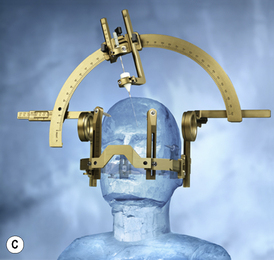
Stereotactic frames were originally designed for stereotactic intracranial surgery, biopsy and electrode placement but have since been extensively adopted for radiosurgery head immobilization, Figure 9.1C. The high level of precision required for radiosurgery, such as Gamma Knife® and X-knife® systems, necessitates a means of relating three-dimensional patient image coordinates to 3D locations in frame coordinates to submillimeter accuracy. The most common system in use is the Leksell Stereotactic System® Frame which is rigidly attached to the patient’s head using four small screws placed with local anesthetic. The frame is shown in figure 9.1C. The frame provides the basis for target coordinate determination and is used to immobilize and position the patient’s head within the radiosurgery collimator helmet. The centre coordinates of the target volume are positioned at the intersection of the beams (from 200 cobalt sources for the Gamma Knife®) so that ‘target-centering’ is always achieved within this geometrically rigid system. Relocatable versions of the stereotactic frame are also available that are closer in design to the ‘head-arc fixation’ method.

Body immobilization


Numerous techniques are available for immobilization of areas other than the head and neck. The major devices used are best discussed in relation to their site-specific needs:


Breast. Treatment of the breast commonly requires the use of three fields – two coplanar glancing beams to the breast and a supraclavicular field. All fields will often make use of the asymmetric collimators to bring one edge of each field to the beam central axis, thereby removing the effect of beam divergence from that one edge. This does not remove the penumbra, and the alignment of the superior edges of the breast fields with the inferior edges of the supraclavicular fields is critical. To achieve accuracy in this set-up requires careful positioning of the patient so that all fields can be treated without moving the patient. The use of a specially designed breast board is preferred. The device may consist of a support which inclines the patient’s upper body and provides an elbow support and/or a hand-grip for the patient to grasp while holding the arm/s above the head; all these positions can be varied to meet the individual requirements of the patient’s treatment and locked into position, linear and angular measurement scales allow the set-up to be recorded and reproduced at each fraction.


Pelvic region. This is one of the most difficult areas of the body to provide effective immobilization. Some systems utilize a single sheet of thermoplastic over the entire abdomen or pelvis that fixes to a baseplate, this is a larger version of that described for the head. An alternative to this is to use a large sealed plastic bag loosely filled with small expanded polystyrene spheres, Vac-Fix™. The bag is manually formed round the patient while the air pressure in the bag is gradually reduced using a vacuum pump. At approximately half atmospheric pressure, the bag becomes rigid and ‘fits’ firmly round the patient, preventing any significant movement. The rigidity can be maintained throughout a course of treatment and until the vacuum is released, when the bag and contents may be re-used for another patient. A variety of shapes and sizes of bag are available to immobilize any part of the anatomy or the whole of the patient, for total body irradiation (TBI), for example. The attenuation in the polystyrene is minimal, but being opaque, consideration must be given to the beam entry ports during the initial evacuation. Radiation damage to the plastic will eventually cause vacuum failure and necessitate the replacement of the bag. Other devices, such as ‘ankle stocks’ and ‘foot rests’, can minimize movement by impeding body rotation or slippage on the treatment couch. The use of a ‘belly-board’ for prone patients, providing a cut-out in the patient support which allows the abdomen to fall anteriorly, ensures that much of the radiosensitive small intestine falls out of the high dose region.


Thorax

Stay updated, free articles. Join our Telegram channel

Mar 7, 2016 | Posted by in GENERAL RADIOLOGY | Comments Off on Radiation treatment planning: immobilization, localization and verification techniques

Full access? Get Clinical Tree

Get Clinical Tree app for offline access