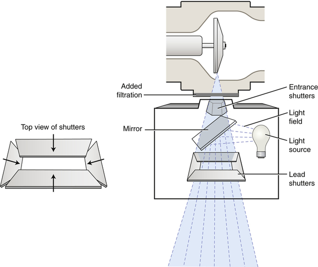
• State the purpose of beam-restricting devices. • Describe each of the types of beam-restricting devices. • State the purpose of automatic collimators or positive beam-limiting devices. • Describe the purpose of a radiographic grid. • Describe the construction of grids, including the different types of grid pattern and grid focus. • List the various types of stationary grids and describe the function and purpose of a moving grid. • Demonstrate use of the grid conversion formula. • Describe different types of grid cutoff that can occur and their radiographic appearance. • Identify the factors to be considered in using a grid. • Recognize how beam restriction and use of grids affect patient radiation exposure. • Explain the air gap technique and describe its use. • Describe the use of shielding accessories to absorb scatter radiation. Chapters 7 and 8 discuss the interactions of x-rays with matter. Scatter radiation is primarily the result of the Compton interaction, in which the incoming x-ray photon loses energy and changes direction. tissue irradiated results in increased scatter production. In addition, using a higher kVp increases x-ray transmission and reduces its overall absorption (photoelectric interactions); however, a higher kVp increases the energy of scatter radiation exiting the patient. Chapter 9 introduces the characteristics of a quality image and explains that scatter radiation provides no useful information about the anatomic area of interest. Controlling the amount of scatter radiation produced in the patient and ultimately reaching the image receptor (IR) is essential in creating a diagnostic-quality image. Scatter radiation is detrimental to radiographic quality because it adds unwanted exposure (fog) to the image without adding any patient information. Digital IRs are more sensitive to lower energy levels of radiation such as scatter, which results in increased fog in the image. Additionally, scatter radiation decreases radiographic contrast for both film-screen and digital images. Increased scatter radiation either produced within the patient or higher-energy scatter exiting the patient affects the exposure to the patient and anyone within close proximity. Therefore the radiographer must act to minimize the amount of scatter radiation produced and reaching the IR. The unrestricted primary beam is cone shaped and projects a round field on the patient and IR (Figure 11-1). If not restricted in some way, the primary beam goes beyond the boundaries of the anatomic area of interest and IR size, resulting in unnecessary patient exposure. Any time the x-ray field extends beyond the anatomic area of interest, the patient receives unnecessary exposure. Limiting the x-ray beam field size is accomplished with a beam-restricting device. Located just below the x-ray tube housing, the beam-restricting device changes the shape and size of the primary beam. The terms beam restriction and collimation are used interchangeably; they refer to a decrease in the size of the projected radiation field. The term collimation is used more often than beam restriction because collimators are the most popular type of beam-restricting device. Increasing collimation means decreasing field size, and decreasing collimation means increasing field size. The relationship between collimation (field size) and quantity of scatter radiation is illustrated in Figure 11-2. As stated previously, collimation means decreasing the size of the projected field, so increasing collimation means decreasing field size, and decreasing collimation means increasing field size. The simplest type of beam-restricting device is the aperture diaphragm. An aperture diaphragm is a flat piece of lead (diaphragm) that has a hole (aperture) in it. Commercially made aperture diaphragms are available (Figure 11-3), as are those that are “homemade” (hospital-made) for purposes specific to a radiographic unit. Aperture diaphragms are easy to use. They are placed directly below the x-ray tube window. An aperture diaphragm can be made by cutting rubberized lead to the size needed to create the diaphragm and cutting the center to create the shape and size of the aperture. Although the aperture’s size and shape can be changed, the aperture cannot be adjusted from the designed size. Therefore the projected field size is not adjustable. In addition, because of the aperture’s proximity to the radiation source (focal spot), a large area of unsharpness surrounds the radiographic image (Figure 11-4). Although aperture diaphragms are still used in some applications, their use is not as widespread as that of other types of beam-restricting devices. Cones and cylinders are shaped differently (Figure 11-5), but they have many of the same attributes. A cone or cylinder is essentially an aperture diaphragm that has an extended flange attached to it. The flange can vary in length and can be shaped as either a cone or a cylinder. The flange can also be made to telescope, thereby increasing its total length (Figure 11-6). Like aperture diaphragms, cones and cylinders are easy to use. They slide onto the tube directly below the window. Cones and cylinders limit unsharpness surrounding the radiographic image more than aperture diaphragms do, with cylinders accomplishing this task slightly better than cones (Figure 11-7). However, they are limited in terms of the sizes that are available, and they are not necessarily interchangeable among tube housings. Cones have a particular disadvantage compared with cylinders. If the angle of the flange of the cone is greater than the angle of divergence of the primary beam, the base plate or aperture diaphragm of the cone is the only metal actually restricting the primary beam. Therefore cylinders generally are more useful than cones. Cones and cylinders are almost always made to produce a circular projected field, and they can be used to advantage for particular radiographic procedures (Figure 11-8). A collimator has two or three sets of lead shutters (Figure 11-9). Located immediately below the tube window, the entrance shutters limit the x-ray beam much as the aperture diaphragm does. One or more sets of adjustable lead shutters are located 3 to 7 inches (8 – 18 cm) below the tube. These shutters consist of longitudinal and lateral leaves or blades, each with its own control. This makes the collimator adjustable in that it can produce projected fields of varying sizes. The field shape produced by a collimator is always rectangular or square unless an aperture diaphragm, cone, or cylinder is placed below the collimator. Collimators are equipped with a white light source and a mirror to project a light field onto the patient. This light is intended to accurately indicate where the primary x-ray beam will be projected during exposure. In case of failure of this light, an x-ray field measurement guide (Figure 11-10) is present on the front of the collimator. It indicates the projected field size based on the adjusted size of the collimator opening at particular source-to-image receptor distances (SIDs). This helps ensure that the radiographer does not open the collimator to produce a field that is larger than the IR. Another problem that may occur is the lack of accuracy of the light field. The mirror that reflects the light down toward the patient or the light bulb itself could be slightly out of position, projecting a light field that inaccurately indicates where the primary beam will be projected. There is a means of testing the accuracy of this light field and the location of the center of projected beam (Box 11-1).
Scatter Control
Introduction
Beam Restriction
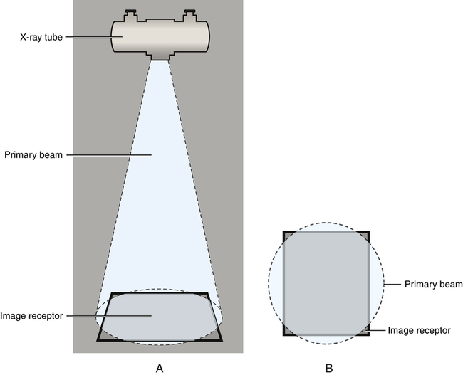
The unrestricted primary beam is cone shaped, projecting a circular field. A, Side view. B, View from above.
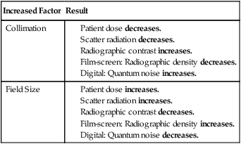
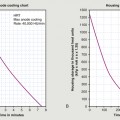
Beam Restriction and Scatter Radiation
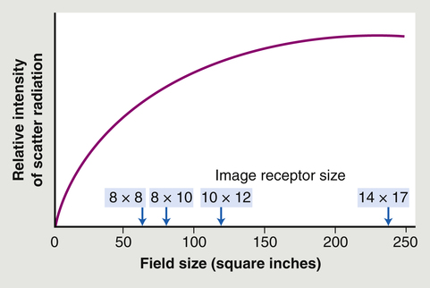
As the field size increases, the relative quantity of scatter radiation increases.
Types of Beam-Restricting Devices
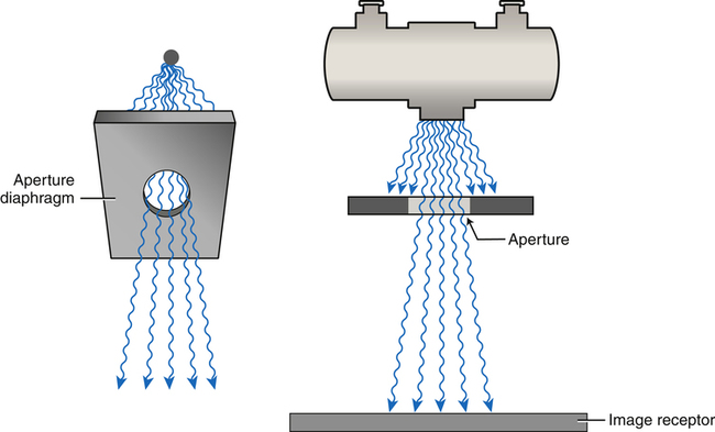
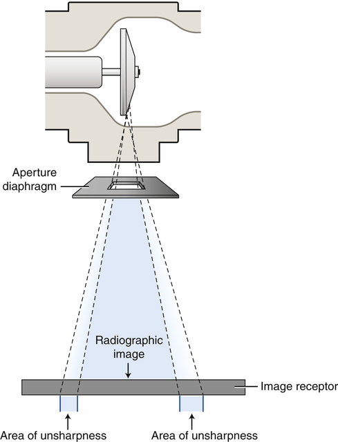
Aperture Diaphragms
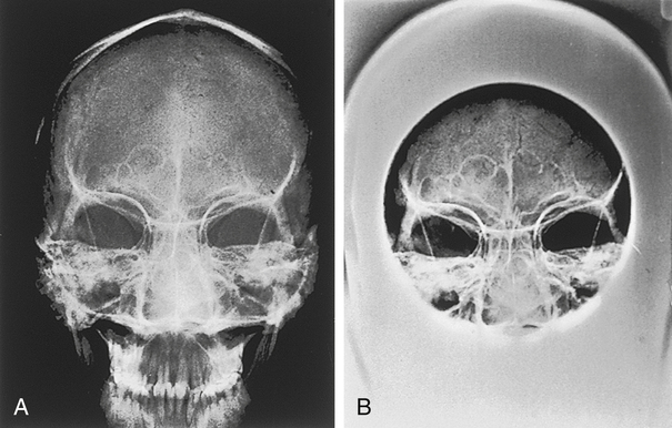
Cones and Cylinders
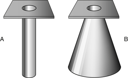
A, A cylinder. B, A cone.
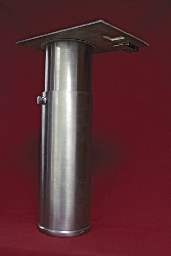
A telescoping cylinder.
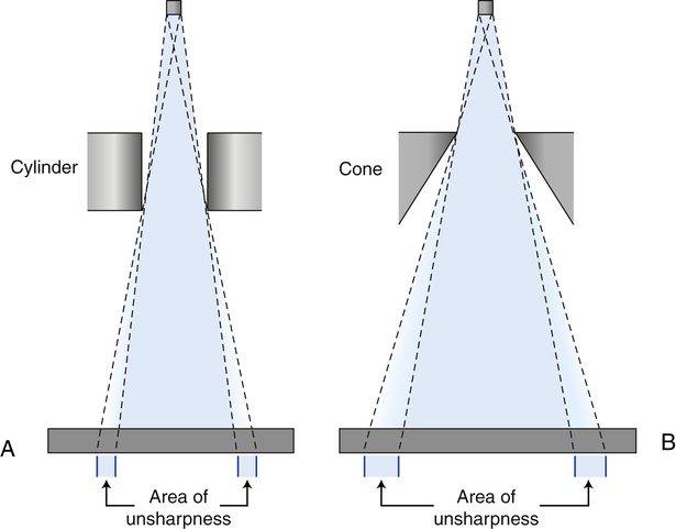
A cylinder (A) is better at limiting unsharpness than a cone (B).
Collimators
 Make the Physics Connection 11-1
 Critical Concept 11-1
 Critical Concept 11-2
 Critical Concept 11-3
 Critical Concept 11-4