Slice Selection
Mark Doyle
OVERVIEW
Slice selection is a fundamental operation applied in almost every imaging sequence. It requires an interacting between the spins in the magnet, the applied gradient and radiofrequency (RF) pulses.
SPINS IN A MAGNET
In the natural (i.e., unmagnetized state) spins are aligned in random orientation and do not produce a net magnetization. When placed in a magnetic field, spins fall into one of two possible orientations:
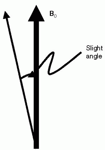
The population of these two energy states is almost equal and is governed by the Boltzman energy distribution. In this way, the magnetization from each aligned (i.e., positive) spin is canceled by the antialigned (i.e., negative) spin. However, at a field strength of 1.5 T there are approximately 3 per 1,000,000 that do not cancel (see Fig. 31-1). Because there are trillions of spins, there is therefore a detectable net magnetization, M0, generated in the body. However, spins never truly align (low energy state) or antialign (high energy state) with respect to the magnetic field; instead, spins can be considered to orient at a slight angle to the main magnetic field, B0 (see Fig. 31-2). This slight angle and the intrinsic spin property become very important for magnetic resonance imaging (MRI), and in particular for slice selection.
ANGULAR MOMENTUM
Spins have the property of angular momentum. Consider that a bicycle resists falling over when in motion due to the properties of the forces of angular momentum, gravity, and tipping forces. The wheels resist tipping over, because perpendicular forces are established in response to the tipping action and the pull of gravity (see Fig. 31-3). Similarly, spins misaligned with B0 will experience perpendicular forces, which in this case are magnetic in nature. The interaction of the spins and the magnetic field causes the spins to precess. Nuclear spins precess at a field-dependent frequency, ω, given by the Lamor equation:
However, in the body there is not just one spin, but there are trillions, each spin precessing in random phase with respect to the others. What we observe is the net result of combining all spins, which becomes resolved into the magnetization, M0, which is oriented along the direction of the main magnetic field.
RADIOFREQUENCY PULSE AND M0
To experience a signal from the net magnetization, M0, we must tip it into the transverse plane. To see how this is accomplished, consider that individual spins precess about B0 at a slight angle. Under this condition, a rotating magnetic field in the transverse plane applied at this precessional frequency will attract spins to the transverse plane (see Fig. 31-4). This applied field is referred to as the RF pulse, because it only need be applied for a short duration on the order of 1 millisecond. Once the M0 magnetization is tipped over into the transverse plane, it will freely precess, again due to the interaction with the main magnet.
SIGNAL DECAY
As individual spins progressively precess, they fall in and out of phase with each other and consequently
lose coherence, leading to signal decay. This loss of coherence can be thought of as being formed by spins initially spanning a small range of orientations relative to each other, with the most advanced spins describing the leading edge, and the lagging spins describing the trailing edge, and all other spins spanning the range between them. As time progresses, the net signal observed is seen to decay in a smooth manner as the range spanned by the spin system gradually widens. The curve describing the signal decay pattern is exponential in nature, with T2 describing the half-life of the spin coherence decay curve.
lose coherence, leading to signal decay. This loss of coherence can be thought of as being formed by spins initially spanning a small range of orientations relative to each other, with the most advanced spins describing the leading edge, and the lagging spins describing the trailing edge, and all other spins spanning the range between them. As time progresses, the net signal observed is seen to decay in a smooth manner as the range spanned by the spin system gradually widens. The curve describing the signal decay pattern is exponential in nature, with T2 describing the half-life of the spin coherence decay curve.
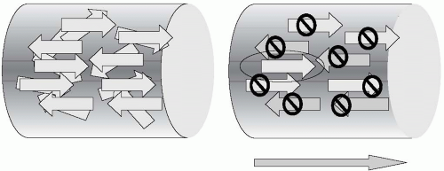 FIGURE 31-1 Outside of the magnetic field, spins are aligned randomly within the body (left panel). When placed in a magnetic field (right panel), spins will either become aligned or antialigned (parallel or antiparallel) with the main magnetic field. The population of the two energy states is almost equal, and therefore each positive spin tends to be canceled by a negative spin. However, a few spins per 1,000,000 (circled) remain unpaired. These unpaired spins are the only ones that contribute to the net magnetization vector. Because there are trillions of spins involved, the net magnetization vector, although small, is in the detectable range and results in a small net magnetization vector. |
SIGNAL DETECTION
A conducting coil placed near a rotating (precessing) magnet will experience a voltage termed an electromotive force (EMF). In other words, the precessing magnet induces a voltage in the conductor, without any direct physical contact occurring. Similarly, the process by which the MRI signal is detected is termed signal induction. From the instant the spin is tipped in to the transverse plane, it freely precesses and can therefore induce a voltage in a conductor placed in its
vicinity. However, as the spins lose coherence with each other, the signal decays. Consequently, the MRI signal is termed a free induction decay, (FID):
vicinity. However, as the spins lose coherence with each other, the signal decays. Consequently, the MRI signal is termed a free induction decay, (FID):
Free, because it freely precesses, that is not a forced precession
Induction, because that is the means of detectionRelated posts:

Stay updated, free articles. Join our Telegram channel

Full access? Get Clinical Tree