Spin Echo
Mark Doyle
OVERVIEW
Spin echo (SE) imaging is a class of imaging sequences that utilize an SE to form an image. This will be introduced in the context of k-space imaging requirements (which are briefly summarized). The major application areas of SE imaging include the following:
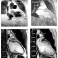
Morphology
Fat or water imaging
T1 contrast
The property that makes SE most suitable for morphologic imaging is the lack of a blood signal, that is, it is a “black blood” sequence.
SPIN ECHO IMAGING—BASIC PRINCIPLES
As is common to all imaging sequences, spatial information is encoded by application of magnetic gradients to the spin system. To form an image, it is necessary to acquire an array of data, and it is convenient to arrange the data in the format required by k-space. When arranged in this manner, generation of an image is straightforward, because application of a Fourier transform will produce an image directly. As was described for gradient echo imaging, to encode each k-space line requires application of two separate gradients:
Frequency encoding gradient, for example, X
Phase encoding gradient, for example, Y
This terminology is common to other imaging sequences such as gradient echo, and again, there is a requirement for a time delay between slice selection and signal read out, which is required for performing phase encoding. In this case, that delay is achieved by recalling the signal as an SE.
SPIN ECHO
Application of an initial radiofrequency (RF) pulse brings the spins into the transverse plane.
Immediately following this, a positive gradient is applied.
A second RF pulse is applied.
This is also followed by a positive gradient.
Spins refocus as an echo during the second positive gradient.
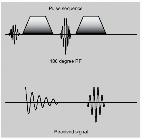 FIGURE 22-1 The basis of the spin echo operation is shown here. In the top panel, the radiofrequency (RF) and gradients are shown and in the lower panel, the received RF signal is shown. Initially, a 90-degree RF pulse is applied and is followed by a positive gradient that causes the signal to decay as spins dephase. This is followed by a 180-degree pulse, which instantaneously reverses the phase conditions of the spin system. Consequently, when a second positive gradient is applied, it serves to unwind the phase of the spin system. At the midpoint of the second gradient, spins come in to phase alignment and form a spin echo signal. |
Application of the initial gradient results in signal decay, because spins that are distributed throughout the imaging slice dephase relative to each other. Application of the second RF pulse causes the spins to instantaneously reverse their trajectory (this is elaborated upon in the following section) and therefore application of a gradient with the same polarity as the initial gradient results in signal regrowth as the spins gradually come back into phase. When all the spins are back in phase, the signal is maximal, and an echo peak is formed. As the gradient continues to be applied, spins lose phase coherence, and the signal decays. The echo time, or TE (i.e., time to the echo), is defined as the time from signal origination to the echo peak.
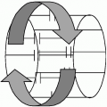
Following application of the first 90-degree RF pulse (in combination with a gradient), the spins dephase. Because the gradient simply adds to or subtracts from the main magnetic field, spins which experience a net increase in the field strength evolve in phase in a positive manner to their final position, whereas spins that experience a net decrease in the magnetic field evolve in phase in a negative manner. Therefore, following application of the first gradient, spins at different locations experience a net phase difference relative to each other. The essential feature to be aware of in the SE is the action of the second RF pulse. The second RF pulse has the strength to completely flip the spin system through 180 degrees (a so-called pancake flip). Consider the spin that was most advanced in phase, following the 180-degree pulse, it is flipped to the phase conditions that would have been produced under a negative gradient. Similarly, the spin that experienced the most negative gradient, when flipped by the 180-degree pulse acts as if its phase evolved in a corresponding positive gradient. Immediately following the 180-degree pulse, the phase of the entire spin system has been effectively reversed. Therefore, application of a second gradient with the same polarity as the original gradient now serves to “unwind” the spins system. This causes the spins to gradually refocus and form the SE.
 FIGURE 22-2 The spin echo (SE) imaging sequence is shown. The transmitted radiofrequency (RF) pulses are applied in conjunction with slice selection gradients. The first RF pulse is 90 degrees and brings the spins into the transverse plane, whereas the second pulse is 180 degrees and refocuses spins as an echo signal. The frequency encoding (measurement) gradient is applied in a positive manner, and split to either side of the 180-degree refocusing pulse. The phase encoding gradient is applied in a stepwise manner, and the signal digitized during the formation of the spin echo. |
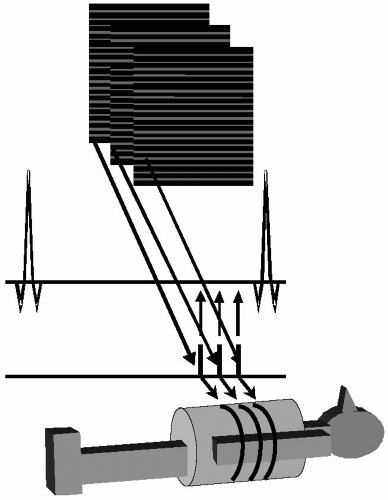 |
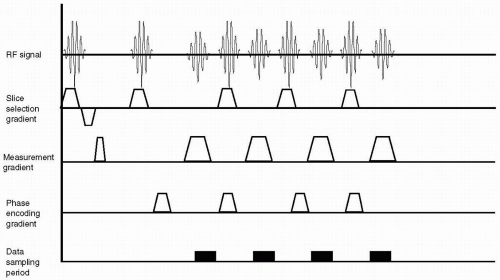 FIGURE 22-4 The fast spin echo sequence is shown. In this rapid scan, several echoes are recalled, with each one contributing to a different line of k-space. For each echo recalled, a separate 180-degree refocusing pulse is applied in conjuction with the slice selection gradients. Each echo of the series contributes to a separate line of k-space corresponding with data sampling. In this way, upwards of 16 lines of k-space can be acquired from a single excitation of the spin system. RF, radiofrequency. |
SPIN ECHO PROPERTIES
Because the second RF pulse refocuses gradients in the same polarity gradient, any gradients that are present due to inhomogeneities in B0 will also be refocused. Therefore, the SE signal is diminished by the T2 process, but not by T2*. To contribute to the SE, spins must receive both RF pulses. Therefore, mobile spins will not fully contribute to an SE


Related posts:
Stay updated, free articles. Join our Telegram channel
Full access? Get Clinical Tree
